
Initial Print Date:12/04
Table of Contents
Subject
Page
Components . . . . . . . . . . . . . . . . . . . . . . . . . . . . . . . . . . . . . . . . . . . . . . . . . . .5
Wiper Drive Unit . . . . . . . . . . . . . . . . . . . . . . . . . . . . . . . . . . . . . . . . . . . . . . .6
Wiper Switch (SWS) . . . . . . . . . . . . . . . . . . . . . . . . . . . . . . . . . . . . . . . . . . . .7
Vehicle Bus System Interfaces . . . . . . . . . . . . . . . . . . . . . . . . . . . . . . . . . . .8
Steering Column Switch Center (SZL) . . . . . . . . . . . . . . . . . . . . . . . . . .8
Safety Information Module (SIM) . . . . . . . . . . . . . . . . . . . . . . . . . . . . . . .8
Central Gateway Module (ZGM) . . . . . . . . . . . . . . . . . . . . . . . . . . . . . . . .8
Light Module (LM) . . . . . . . . . . . . . . . . . . . . . . . . . . . . . . . . . . . . . . . . . . .9
Car Access System (CAS) . . . . . . . . . . . . . . . . . . . . . . . . . . . . . . . . . . . .9
Power Module (PM) . . . . . . . . . . . . . . . . . . . . . . . . . . . . . . . . . . . . . . . . . .9
Instrument Cluster (Kombi) . . . . . . . . . . . . . . . . . . . . . . . . . . . . . . . . . . . .9
Control Display (CD) . . . . . . . . . . . . . . . . . . . . . . . . . . . . . . . . . . . . . . . . .9
Dynamic Stability Control (DSC) . . . . . . . . . . . . . . . . . . . . . . . . . . . . . . .9
Rain/Light Sensor (RLS) . . . . . . . . . . . . . . . . . . . . . . . . . . . . . . . . . . . . . . . . .9
Wet-Arm Heater (NAH) . . . . . . . . . . . . . . . . . . . . . . . . . . . . . . . . . . . . . . . . .11
Wiper Position . . . . . . . . . . . . . . . . . . . . . . . . . . . . . . . . . . . . . . . . . . . . . . . .13
Regulated Wiper Speed . . . . . . . . . . . . . . . . . . . . . . . . . . . . . . . . . . . . . . . .13
Reverse Wiper Control . . . . . . . . . . . . . . . . . . . . . . . . . . . . . . . . . . . . . . . . .13
Wiper Stages 1 and 2 . . . . . . . . . . . . . . . . . . . . . . . . . . . . . . . . . . . . . . . . . .14
Rain Sensor Operation . . . . . . . . . . . . . . . . . . . . . . . . . . . . . . . . . . . . . . . . .14
Single Wipe . . . . . . . . . . . . . . . . . . . . . . . . . . . . . . . . . . . . . . . . . . . . . . . . . . .15
Alternating Park Position (APS) . . . . . . . . . . . . . . . . . . . . . . . . . . . . . . . . . .15
Windshield Washer System (SWA) . . . . . . . . . . . . . . . . . . . . . . . . . . . . . .16
Wet-Arm Heater (NAH) . . . . . . . . . . . . . . . . . . . . . . . . . . . . . . . . . . . . . . . . .17
Headlight Cleaning System (SRA) . . . . . . . . . . . . . . . . . . . . . . . . . . . . . . .17
Snow Mode . . . . . . . . . . . . . . . . . . . . . . . . . . . . . . . . . . . . . . . . . . . . . . . . . .18
Blocking Protection . . . . . . . . . . . . . . . . . . . . . . . . . . . . . . . . . . . . . . . . . . . .18
Sluggish Mode . . . . . . . . . . . . . . . . . . . . . . . . . . . . . . . . . . . . . . . . . . . . . . . .19
E65 Windshield Wiping and Washing
Revision Date:

Subject
Page
Service Position . . . . . . . . . . . . . . . . . . . . . . . . . . . . . . . . . . . . . . . . . . . . . . .19
Washer Jet Cleaning Function . . . . . . . . . . . . . . . . . . . . . . . . . . . . . . . . . .20
Check Control Messages . . . . . . . . . . . . . . . . . . . . . . . . . . . . . . . . . . . . . .20
Diagnosis . . . . . . . . . . . . . . . . . . . . . . . . . . . . . . . . . . . . . . . . . . . . . . . . . . . . .21
Default Values . . . . . . . . . . . . . . . . . . . . . . . . . . . . . . . . . . . . . . . . . . . . . . . . .22
Assembly position for the replacement of the wiper drive unit . . . . . . .22

3
E65 Windshield Wiping and Washing
E65 Windshield Wiping and Washing
Vehicle: E65/E66
Production: All
After completion of this module you will be able to:
• Identify and locate windshield wiper components
• Understand E65 windshield wiper systems

Introduction
To meet the rising expectations of customers in the future, the wiper system was redevel-
oped to achieve the following design goals:
• User-friendly
• Quiet
• Low operating costs
For the first time, the windshield wiper uses an electronically reversible wiper control
(like the rear window wiper of the E39/E53). The reversing gear and the relay are no
longer needed.
The main advantages compared with previous conventional wiper systems are:
• Improved accuracy of wiping angle in the reversing direction.
• Reduced wiper noise.
• Wiper arm speed is dependent on the wiper arm position on the windshield.
• Less space is required for the wiper linkage because the motor rotation is limited
to 180º.
• The wiper system adapts to snow load within the minimum field of view.
• The wiper arms have alternating park positions.
4
E65 Windshield Wiping and Washing
5
E65 Windshield Wiping and Washing
System Overview
Components
The components that make up the wiper system are:
• Wiper drive unit
• Wiper switch
• Vehicle bus system interface
• Rain/Light Sensor (RLS)
• Windshield and headlight washer system (pumps and tank)
• Wet-arm heater elements
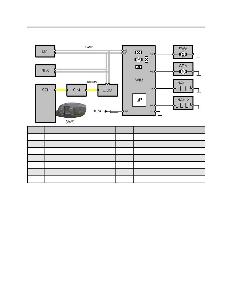
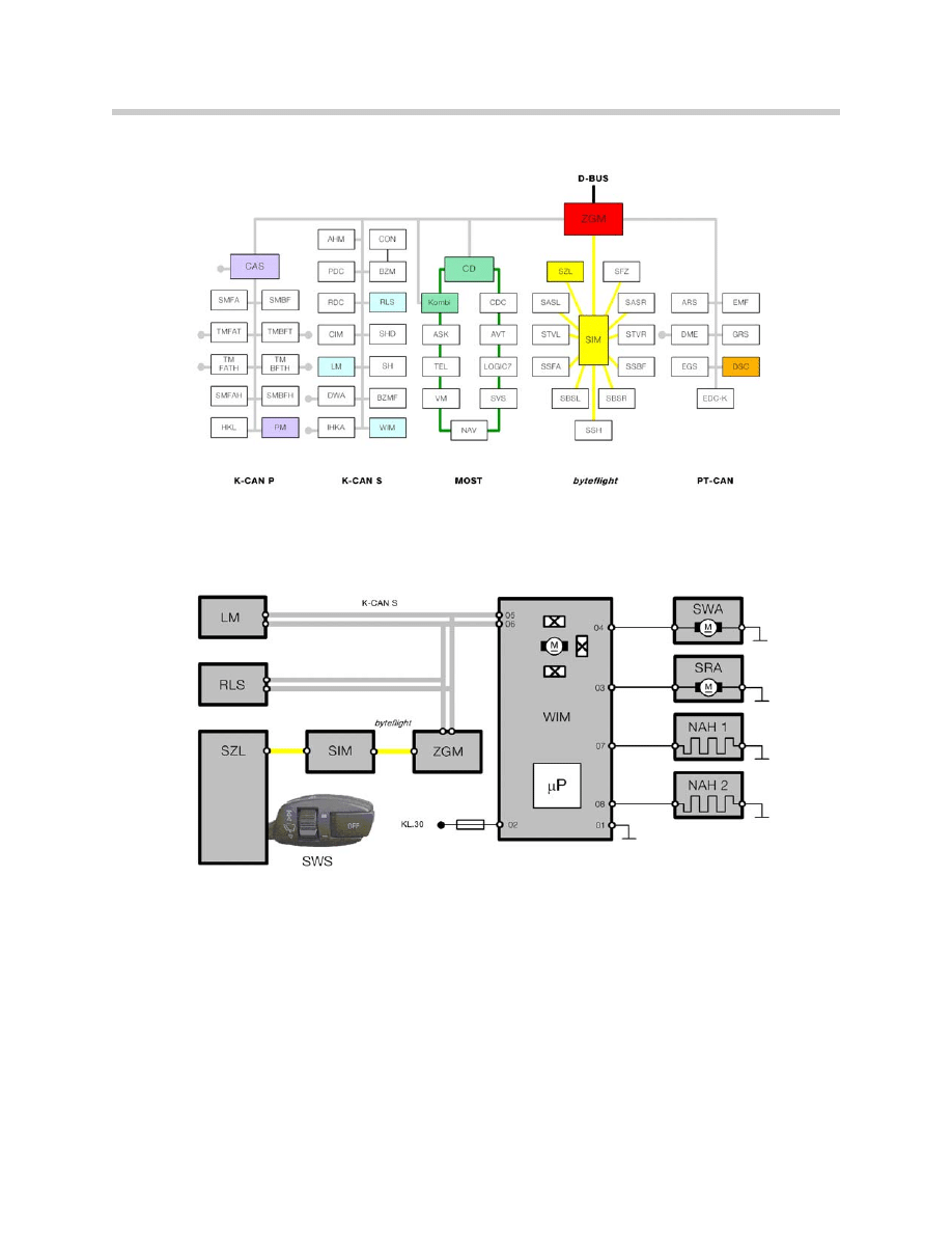
Index
Explanation
Index
Explanation
WIM
Wiper Module
SWS
Wiper Switch
RLS
Rain/Light Sensor
KL30
Terminal 30 (B+)
LM
Light Module
SWA
Windshield Washer System
SZL
Steering Column Switch Center
SRA
Headlight Washer System
SIM
Safety and Information Module
NAH 1
Wet-Arm Heater, left
ZGM
Central Gateway Module
NAH 2
Wet-Arm Heater, right
K-CAN S
K-CAN System
byteflight
Safety Bus for ISIS (fiber optic)
6
E65 Windshield Wiping and Washing
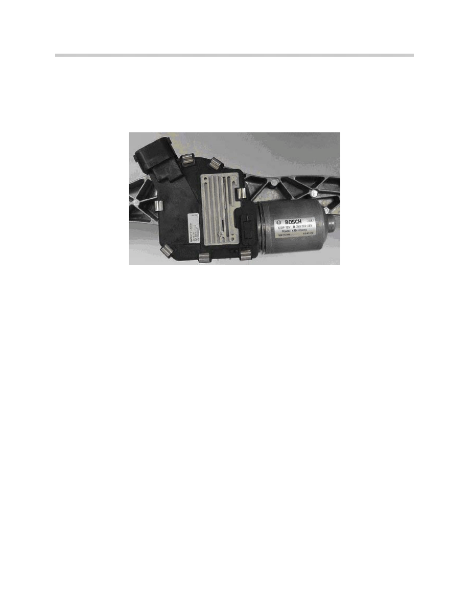
Wiper Drive Unit
The wiper system used in the E65 is designed as a two-arm/synchronization wiper sys-
tem with an attached wiper drive. The wiper arms are guided by a swinging arm (crank
with coupling link) on the driver's side and by a transverse link and a four-bar linkage on
the front passenger's side.
The wiper drive contains the following components:
• Reversible motor
• Reduction gear (worm gear)
• Gear case cover with integrated wiper module (WIM)
The wiper module is integrated in the wiper drive. The wiper module controls
all wipe/wash functions.
The wiper module contains:
• Output stages for the wiper motor, washer pump and wet-arm heaters
• Position sensing by 3 Hall sensors
• K-CAN S interface
• Control unit
The position of the motor armature is detected by 3 hall sensors:
• 2 Hall sensors in connection with a ring magnet on the armature shaft.
• 1 Hall sensor and a magnetic disc on the gear wheel.
The two 2 Hall sensors on the armature shaft are installed in the wiper motor.
The signals are used to determine:
• Wiper motor speed
• The direction of rotation of the wiper motor

7
E65 Windshield Wiping and Washing
The measurement is required for:
• Regulated wiper speed
• Snow mode detection
• Sluggish mode
• Lock up protection
A Hall sensor and a magnetic disc are mounted to the gear wheel of the wiper motor,
they are used to determine the reference position of the wiper motor shaft.
The zero position can be reached when the reference position is determined.
• Zero position = park position.
Note: The Hall sensor on the gear wheel replaces the previous mechanical
park contact.
Wiper Switch (SWS)
The wiper switch is essentially an
incremental switch, it does not lock into
any positions. A “roll” mode is integrat-
ed in the operating concept. This
allows one-touch control of wiper
speed.
Roll mode: 1 tap up = stage 1
2 taps up = stage 2
From stage 2: 1 tap down = stage 1
2 taps down = off
3 taps down = single wipe
Pushing the wiper switch upwards past the detent activates stage 2.
A push button (1) used to turn the Rain/Light Sensor system on and off is on the end of
the wiper switch. A four position thumb wheel (2) controls the sensitivity. The function
status is indicated by LED (3).
A wash cycle is requested by pulling the stalk towards the driver.
The driver requests for the functions of the wiper system are signalled using Hall sensors
inside the wiper switch. The sensor signals are interpreted by the Steering Column
Switch Center (SZL).
8
E65 Windshield Wiping and Washing
Vehicle Bus System Interfaces
Steering Column Switch Center (SZL)
The SZL evaluates the signal from the windshield wiper switch and calculates the wiper
system function requested by the driver. The bus message is sent out on the byteflight.
Note: If communication between the wiper switch and the wiper module is
disturbed, the failsafe result is continuous operation of the wipers.
Safety Information Module (SIM)
The SIM receives the driver's command from the SZL and relays it to the Central
Gateway Module (ZGM) by byteflight.
Central Gateway Module (ZGM)
As a gateway control unit, the ZGM receives the message from the SIM and relays
the message to the Wiper Module via the K-CAN S.

9
E65 Windshield Wiping and Washing
Light Module (LM)
The LM communicates to the wiper module when the parking lights are. This signal
is used to enable the SRA (headlight cleaning system) function.
Car Access System (CAS)
Terminal status is received from the CAS via the K-CAN S.
Power Module (PM)
The System voltage is monitored by the Power module and communicated to all
control units via the K-CAN P bus.
Instrument Cluster (Kombi)
The instrument cluster provides the following information:
• Ambient temperature (wet-arm heater, defect code memory)
• Time (alternating park positions)
• Washer fluid level
The instrument cluster displays the Check Control messages: "wiper fault" or
"refill washer fluid".
Control Display (CD)
Extended Check Control messages are displayed by the Control Display.
Dynamic Stability Control (DSC)
The DSC supplies the road-speed signal for the speed-dependent wiper functions.
Rain/Light Sensor (RLS)
The Rain/Light Sensor is standard
equipment, it is installed below the
base of the rear view mirror as in other
models.
The rain/driving light sensor in the E65
is an improved version of the first-gen-
eration rain sensor.
An additional driving light sensor is
integrated into the rain/driving light sen-
sor.
This function is described separately in
the vehicle lighting chapter.
1. Optical element bonded
to windshield
2. RLS sensor
3. Plug connection
4. Measurement diodes
5. light sensor
10
E65 Windshield Wiping and Washing
Modifications from the first-generation rain sensor:
• There are now 4 optical measurement sections instead of 2 which
provides improved identification of dirt, salt etc.
• Integration of the light sensor function.
• K-CAN S interface
• Flash Programmable EEPROM.
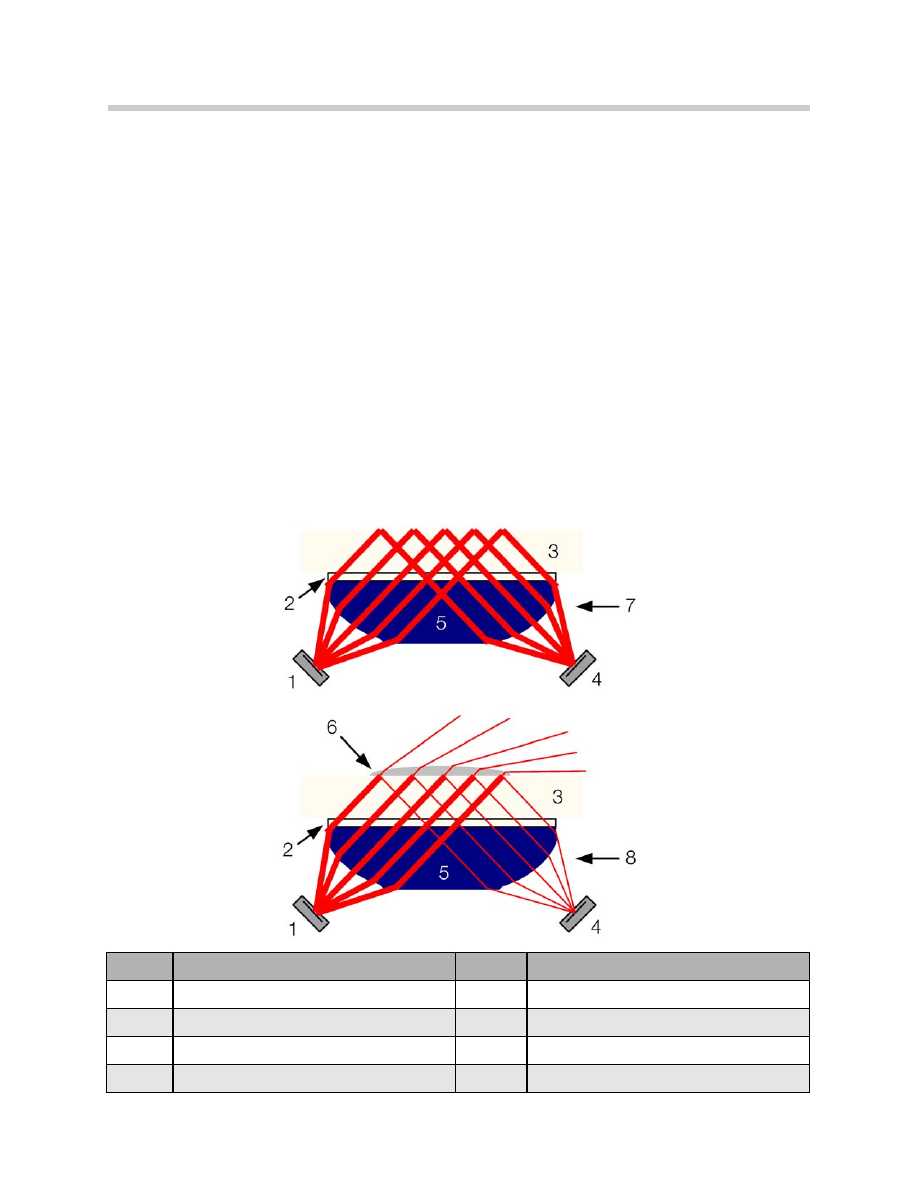
The measuring principle of the RLS is identical to that of the previous rain sensor
(AIC, automatic interval control).
The rain detection function is based on the principle of total reflection against the
glass-to-air boundary surface:
• When the windshield is clean and dry, the infrared light transmitted by the
rain/driving light sensor is fully reflected.
• When the windshield is wet or dirty in the area of the reflective surfaces, the condi-
tions for total reflection no longer exist. As a result, less light is reflected.
Index
Explanation
Index
Explanation
1
Transmitter
5
Optical element
2
Adhesive
6
Rain drop
3
Windshield
7
High intensity light
4
Receiver
8
Reduced intensity light

11
E65 Windshield Wiping and Washing
This change in the signal is evaluated by a microprocessor in the Rain/Light sensor
(together with other signals, e.g. speed).
If necessary, a message is sent to the wiper module via the K-CAN S.
The wiper module then:
• Activates the wipe operation
• Determines the wiper speed and the interval duration
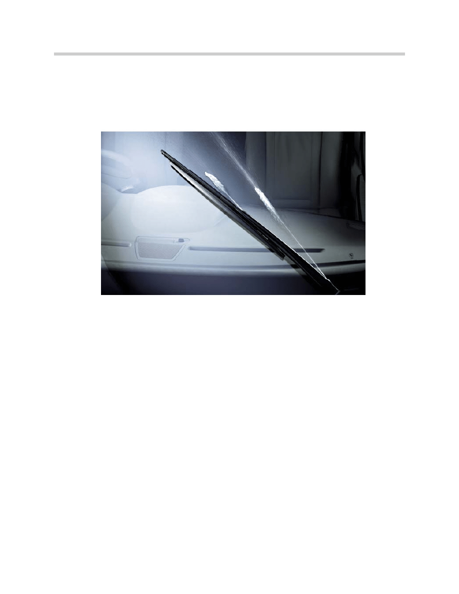
Wet-Arm Heater (NAH)
The washer fluid in the washer fluid hose is heated electrically in the wiper arm.
There is a connector at the lower end of each wiper arm. The washer fluid hose is routed
through this connector to the washer nozzle outlet at the end of the wiper arm.
A constant voltage wire, which is heated by the application of current, is integrated in the
washer fluid hose. The constant voltage wire extends the full length of the washer fluid
hose in the wiper arm.
Washer nozzles
Passenger Wiper Arm
Washer fluid hose with internal heating wire

12
E65 Windshield Wiping and Washing
Principle of Operation
In combination with the wiper switch and the Rain/Light Sensor,
the wiper drive has the following functions:
• Regulated wiper speed
• Reversible wiper control
• Wiper stages 1 and 2
• Rain sensor operation
• Single wipe
• Alternating park positions (APS)
• Windshield washer system (SWA)
• Wet-arm heater (NAH)
• Headlight cleaning system (SRA)
• Snow mode
• Blocking protection
• Sluggish mode
• Service position
• Washer jet cleaning function
• Check Control messages
• Diagnosis
13
E65 Windshield Wiping and Washing
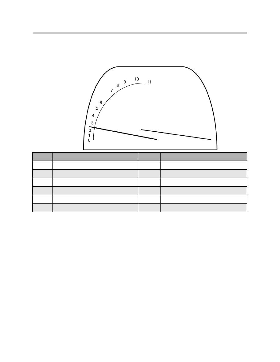
Wiper Position
Depending on wiper functionality, the wiper moves into various positions on the
windshield:
Regulated Wiper Speed
Wiping frequency and wiper arm speed are regulated according to:
• Wiper stage
• Vehicle speed
• Wiping direction
As a result, system voltage is compensated. The characteristics files for wiper speed
are stored in the EEPROM.
Reverse Wiper Control
Activation of the wiper system by reversing of the wiper motor is implemented in the
wiper electronics. This reduces the space required by the wiper linkage.
Overrun of the wiper positions is prevented, as the wiper motor is braked in the end posi-
tion. By changing the polarity of the supply, the wiper motor stops suddenly without run-
ning on.
Index
Explanation
Index
Explanation
0
Lowest possible position
6
Blocking limit, minimum range for down stroke
1
Assembly position
7
Rain/Light sensor, up stroke limit
2
Park position, moving down
8
Rain/Light sensor, down stroke limit
3
Park position, moving up
9
Service position (wiper arms)
4
Lower reversing position for intermittent wipe
10
Blocking limit, minimum range for upstroke
5
Lower reversing position for stage 1 and 2
11
Upper reversing position

14
E65 Windshield Wiping and Washing
Wiper Stages 1 and 2
The wiper is energized via a signal generated by the wiper switch in stage 1 or stage 2.
Once switched on, the wiper moves immediately if terminal R is "on".
The wiper moves into the reversing positions at reduced speed (PWM) to ensure that the
wiper arms move smoothly.
Note: The wiper is switched off when terminal R is "off"
When terminal R is "off", the wiper stops immediately, (the wiper can stop in the middle
of the windshield).
For safety reasons, the wiper arms are not moved until the windshield wiper switch is
actuated again.
Rain Sensor Operation
The Rain/Light Sensor controls the interval duration and the wiper speed after pushing
the contact button on the side of the wiper lever.
The aim of rain sensor operation is to relieve the strain on the driver by automatically con-
trolling the wipers. Even in very different rain situations, manual intervention is no longer
necessary.
The wiper motor speed is controlled steplessly by means of a PWM signal. The
Rain/Light Sensor sets the wiper motor speed depending on the degree of rain/snow on
the windshield.
A defined minimum speed is maintained in order to avoid skipping of the wiper blades.
This minimum speed is 35 wipe strokes per minute.
Wiper speed control is performed in addition to the interval duration. As of a certain rain
intensity, adjustments are made to the wiper speed control only.
After every wiping cycle, the wiper motor moves into the reversing position. If the wiper
motor is not triggered again by the Rain/Light Sensor within a period of 3 minutes, the
wiper motor moves into the park position.
Sensitivity can be adjusted manually in 4 stages with the thumbwheel on the wiper
switch.
After KL R is switched off, if the rain sensor is required the button must be pressed again.

15
E65 Windshield Wiping and Washing
Single Wipe
If the wiper switch is pushed down in the direction of single wipe mode, wiper stage 1 is
activated as long the switch is held.
After releasing the single wipe position, this wiping motion is terminated when the wiper
reaches the alternating park position.
The reversing position during the single wipe operation corresponds to the reversing
position in stage 1.
The single wipe function can also be activated during rain sensor operation.
Alternating Park Position (APS)
The wiper control recognizes two park positions outside the field of view of the driver. In
the park position, the wiper control alternates between the following park positions every
4 days:
• Lower park position
• Upper park position
This feature prevents permanent deformation of the wiper blade rubber. The wiper mod-
ule decides whether the upper or the lower park position has been selected on the basis
of the wiper-arm time in a certain park position. For this purpose, a K-CAN S message
(year/month/day) from the Kombi is evaluated. This ensures that the wipers are parked as
evenly as possible (50 : 50).
The wiper are moved to the alternating park positions under the following conditions:
• Terminal R "off" and wiper off (wiper is in park position).
16
E65 Windshield Wiping and Washing
Windshield Washer System (SWA)
A washing program is activated depending on the wiper position, direction of movement
and the actuation time of the windshield washer switch. During each upward stroke of
the wiper arm, the windshield is wet using 2 nozzle outlets in both wiper arms in front of
the wiper blade.
Washing program:
• Washer contact is operated.
• Washer pump is activated.
• The upwards stroke of the wiper is executed with a delay of 500 ms.
This delay ensures that the wiper blade is pre-wet.
• Shortly before reaching the upper reversing position, the washer pump is
deactivated in order to reduce soiling of the side windows.
• The windshield is not wet during the downward stroke
(the downward stroke dries the windshield).
• After releasing the washer contact, 3 final wiping cycles are executed
(three complete upward/downward strokes).
If the rain sensor is activated, a final wipe cycle (three continuous wiping operations)
is executed. The control unit then switches back to rain sensor operation.
An intensive cleaning system such as in the E38 is no longer used.
The reasons for this are:
• Customer servicing costs
• Environmental concerns

17
E65 Windshield Wiping and Washing
Wet-Arm Heater (NAH)
For the first time in a BMW, a wet-arm heater is used for the E65. On the E65, there are
no conventional heated washer jets in the hood.
In the wet-arm heater, the hoses for the washer fluid are in the wiper arm. This part of the
washer fluid hose is electrically heated. The outlets of the windshield washer system are
integrated in the wiper arm.
The washer fluid hose is heated using a PWM signal to control the current flow:
• With terminal R "on"
• Depending on the ambient temperature
• Depending on the battery voltage: with power reduction (battery load with priority 5,
6 via CAN) the power supply to the wet arms is decreased in half.
This can double defrosting times compared with normal times. The wet-arm heater is
switched off while terminal 50 is "on".
Headlight Cleaning System (SRA)
The headlight washing system is available as of the “parking light on” signal being
received by the WIM from the LM.
A headlight wash has 2 spraying cycles.
A headlight wash is activated automatically:
• When the ignition and the light are "on", a headlight wash is always
activated the first time the windshield washer system is operated.
• After the first operation, every 5th time a windshield washing operation is activated.
Following a cycle, no further cycles can be activated within an inhibit period of 5 minutes.
The timed arrest and the SRA counter are reset by terminal R "off".
If the control unit identifies the need to refill the water tank, a headlight wash is only acti-
vated with every eighth wash requested. This requirement is identified by the Instrument
Cluster (message via K-CAN S).

18
E65 Windshield Wiping and Washing
Snow Mode
When the windshield is covered with snow, the wiping action produces wedges of snow
at the upper and lower limits of the wipers. These wedges of snow can sometimes block
the wipers.
To avoid blocking protection, the wiping area is reduced slightly. The wiper area is
reduced within the limits of visual safety.
The wiper system enters snow mode when an increased load is detected in the lower or
upper area of the windshield. This prevents the wiper from overheating and cutting out
when snow wedges at the edge of the wiping range make it extremely difficult for the
wipers to move.
Snow mode is identified based on the following parameters:
• Wiper arm speed
• PWM voltage (increase in current needed to maintain current wiper speed)
In snow mode, the wiper control continuously tries to increase the wiper range until nor-
mal operation is restored.
Blocking Protection
If the wiper cannot wipe the regulation required windshield area on account of difficulty to
move, the blocking protection trips under the following conditions:
• If blocking is detected, the wiper is initially switched off for 1 second. Following this,
up to 3 restart attempts are performed.
• If the wipers are still blocked, the wiper arms are stopped in the lowest possible
position.
• The washer pump is inhibited.
• The pump of the headlight cleaning system is inhibited.
For safety reasons, wiping is not automatically restarted after the blocking pro-
tection has tripped in order to protect the customer from injury if he/she tries to
free the wiper while it is still switched on!
The blocking protection is not cancelled until the wiper is switched on again.

19
E65 Windshield Wiping and Washing
Sluggish Mode
If the wiper control detects an increase in load across the central portion of the wind-
shield (based on the parameters wiper arm speed and PWM voltage), the wiper goes
to sluggish mode.
In sluggish mode, wiper speed is decreased and the wiper setting is reduced to max.
stage 1. The wiper remains functional even when it is extremely difficult to move.
The wiper does not overheat or is not switched off even if it is extremely difficult to
move due to mechanical jamming or application of force.
Workshop Hints
Service Position
To replace the wiper blades, the wiper arms must be moved to the service position:
• Switch off terminal R by pressing the start/stop button.
• Lift the wiper stalk past the detent (position 2) within a minute and hold it for
3 seconds.
The wipers move to the service position and stop in this position (the wipers are posi-
tioned almost vertically on the windshield).
The wipers do not return to the park position until terminal R is "on" and a wiper stage
is switched.
20
E65 Windshield Wiping and Washing
Washer Jet Cleaning Function
The washer jet cleaning function is used to clean the washer jets, check the quality of the
spray jets and to monitor the wiper arm or washer jet setting in relation to the windshield
after assembly work and servicing.
The washer jet cleaning function is activated when:
• The wiper arms are in the park position.
• Terminal R is "off".
• The washer pump contact is actuated continuously for at least 3 seconds within 60
seconds (activation period).
The washer jet cleaning function can be activated several times within the 60 s activation
period. Here is how the washer jet cleaning function works:
• The washer pump of the windshield washer system (SWA) is activated as long as
the windshield wiper switch (SWS) is actuated.
• Pulsed at full capacity for 30 seconds.
• No wiper arm motion.
Check Control Messages
The functions of the wiper system are monitored by the instrument-cluster control unit as
from terminal R "on".
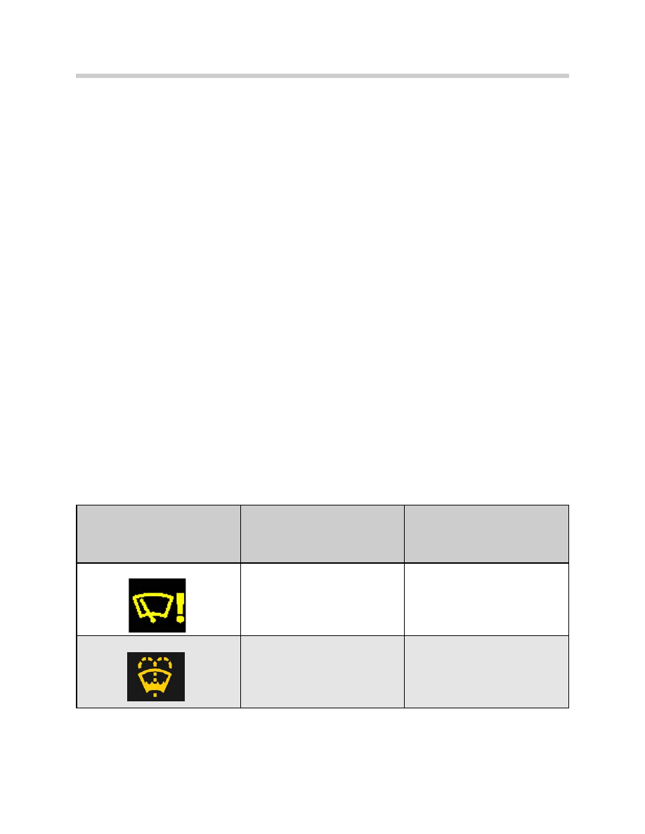
In the event of a malfunction, the following Check Control messages are displayed in the
instrument cluster:
Check Control Message
displayed in Kombi
Message displayed in Control
Display
Cause
Windshield wiper fault!
“Windshield wiper fault!”
Temporary windshield wiper fault.
Wipers may remain in continuous
operation. Please contact nearest
BMW center.
Faulty communication to WIM mod-
ule or WIM malfunction.
Refill Washer fluid
Washer fluid reservoir nearly empty

21
E65 Windshield Wiping and Washing
The wiper module does not generate the Check Control message "refill washer fluid".
The instrument cluster is responsible for monitoring the washer fluid level.
Diagnosis
The wiper module has a non-volatile defective code memory. The wiper module and
interface signals are checked for plausibility. If a fault occurs, the following fault messages
can be stored:
• Washer pump or cable short circuit or open circuit or reservoir empty
• SRA (headlight wash system) pump or open circuit in cable or short circuit to ground
• Wet-arm heater or open circuit in cable or short circuit to ground
• Wiper sluggish
• Fault Hall sensor 1 armature
• Fault Hall sensor 2 armature
• Fault Hall sensor zero position
• Encoding error
• Internal control unit fault
• CAN fault
The following environmental conditions are
stored in addition to the type of fault:
• Frequency
• Ambient temperature
• Battery voltage
• Mileage or km

22
E65 Windshield Wiping and Washing
Default Values
Faulty or missing variable
Default value
Windshield wiper switch
Wiper stage 1 "on"
Rain/driving light sensor
Intermittent control
Vehicle speed
60 km/h
Terminal R and terminal 50
Terminal R "on"/terminal 50 "off"
Ambient temperature 0ºC
Parking light
Parking light "on"
Wiper fluid level
Reservoir almost empty
Date (year/month/day)
Last valid date
Battery load reduction
No reduction
Battery voltage 13.6
V
Assembly position for the replacement of the wiper drive unit
To simplify removal and installation of the wiper drive, move the wiper motor into the
assembly position.
In the Diagnosis Program , select "Assembly mode" under "Service Functions".
The wiper then moves into the zero position.

23
E65 Windshield Wiping and Washing
Classroom Exercise - Review Questions
1.
How does the wiper module detect the “park” position of the windshield wipers?
2.
How does the wiper drive receive the driver requests for wiper operation?
Describe the component and signal path.
3.
Are the Washer nozzles of the E65 adjustable? How are they heated?
4.
What makes it possible for the E65 windshield wiper system to have variable upper
and lower wiper positions based on detected conditions (e.g. snow, blocking etc.).
5.
What is the procedure required to put the wipers into the service mode? Is there
any procedure that must be followed before removing and replacing the wiper
drive unit?
Document Outline
- Main Menu
- Intro to Advanced Body Electronics
- E65 Power Management
- E65 Power Module
- E65 Car Access System
- E65 Driver Information
- E65 Body Electronics
- E65 Central Body Electronics
- E65 Remote Control Services
- E65 Automatic Trunk Lid Lift
- E65 Windshield Wiping Washing
- E65 Seat, Mirror and Steering Column
- E65/66 Model Update
- E65/66 Comfort Access
- E6x Voltage Supply and Bus Systems
- E6x Body Electronics
- E6x Body Electronics
- E6x 9/05 Model Updates
- E6x Driver Information Systems
- E90 Voltage Supply and Bus Systems
- E90 General Vehicle Electrical
- E90 General Vehicle Electrical
- E90 General Vehicle Electrical II
- E90 Driver Information Systems
- E90 Entertainment and Communication
- Car Communication Computer
- Head-Up Display
- Head-Up Display (First Generation)
- E70 Head-Up Display (Second Generation)
- E70 Audio Systems
- BMW Night Vision
- Glossary
Wyszukiwarka
Podobne podstrony:
17 E65 Windshield Wiping & Washing
04d E65 Speech Processing System
zx 04d
Osprey CAM 140 Monongahela 1754 55 Washington's defeat, Braddock's disaster
04d domowe odp
FIG 04D
NewYorkTimes&WashingtonPost
9,10 Washington Irving
Jura Impressa E40 E45 E60 E65
BMW 7 E65 2005pl
FIG-04D
04d klasowe odp
BMW 7 E65 2005 Keylesspl
Washington Irving UPIORNY NARZECZONY
The NY Times i The Washington Post, DIKS, ZSM
04d RACHUNEK ZYSKÓW I STRAT
04d samoistne krwiaki sródmózgowe
zx 04d
irving washington the broken heart
więcej podobnych podstron