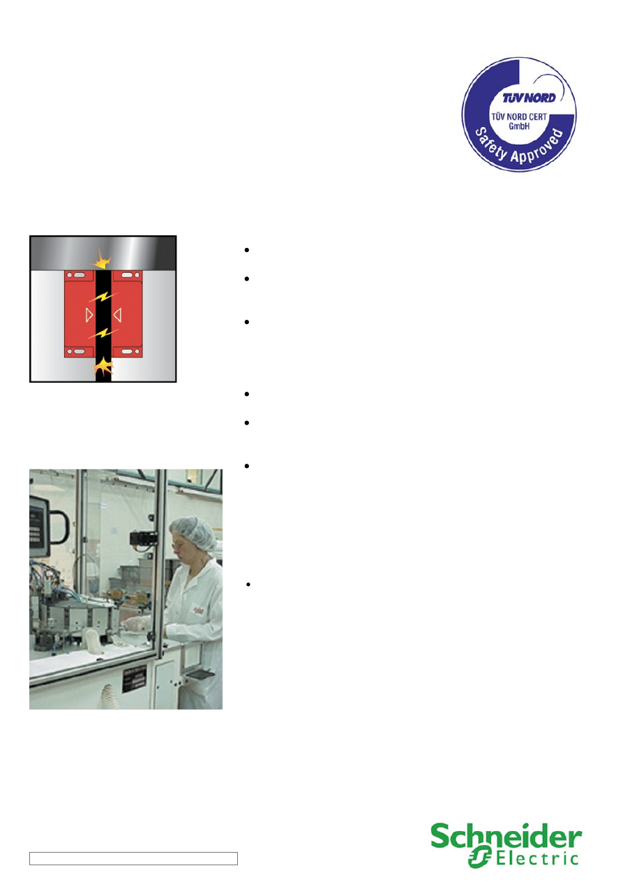
Safety Chain Solution – Magnetic switches
PL e, SIL 3
High diagnostic level with an optimized
implementation
Function:
Safety-related stop function initiated by any of the moveable
guards that helps protect the access to the hazardous area.
The opening of each guard is detected by using magnetic
switches, which are checked by the safety module by means of a
combination of contacts (normally closed and normally open).
Opening of any of these guards causes the deactivation of the
safety module outputs, which results in the switching-off of the
motor power supply by means of the contactors K1 and K2 (stop
category 0 according to EN/IEC 60204-1) to help prevent possible
hazardous movements or states.
The main contactors are monitored by the safety module to
detect contact welding by means of the mirror contacts.
The safety module also monitors the consistent actuation of the
magnetic switch contacts to detect any failure, before restart of
the machine movement is permitted.
Opening or removal of the protective guard is detected by means
of the coded magnetic switches, which are particularly useful for
guards without accurate guidance and for use in difficult
environments (dust, liquids, etc.).
Typical applications:
Assembling, packaging or similar compacted machines with a short rundown
time and where the access to the hazardous area is very frequent.
SCS06/0310 - 03-03-2010
Safety Chain Solution – Magnetic switches
Design:
The safety function employs well-tried safety principles and is robust in the event of a component failure by means of two
redundant contacts on the magnetic switch device and two redundant contactors (K1 and K2).
The contact synchronization of the magnetic switches and contactor failure are detected by the safety module at the next demand
upon the safety function.
The start (S2) and the restart interlock (S1) pushbuttons must be located outside the hazardous area and at a point from which the
potential danger is visible.
The safety module satisfies the requirements for performance level PL e in accordance with EN ISO 13849-1 and SILCL 3 in
accordance with EN/IEC 62061.
The contactors (K1 and K2) are considered as well-tried components.
Protection against overcurrent must be provided in accordance with EN/IEC 60947-4-1
The contactors (K1 and K2) have mirror contacts in accordance with EN/IEC 60947-4-1, which are integrated into the feedback of
the safety module L1 for fault detection.
Related products
Switches, pushbuttons, emergency stop -
Switch mode Power supply -
Coded magnetic system -
Modular beacon and tower light -
SCS06/0310 - 03-03-2010
Safety Chain Solution – Magnetic switches
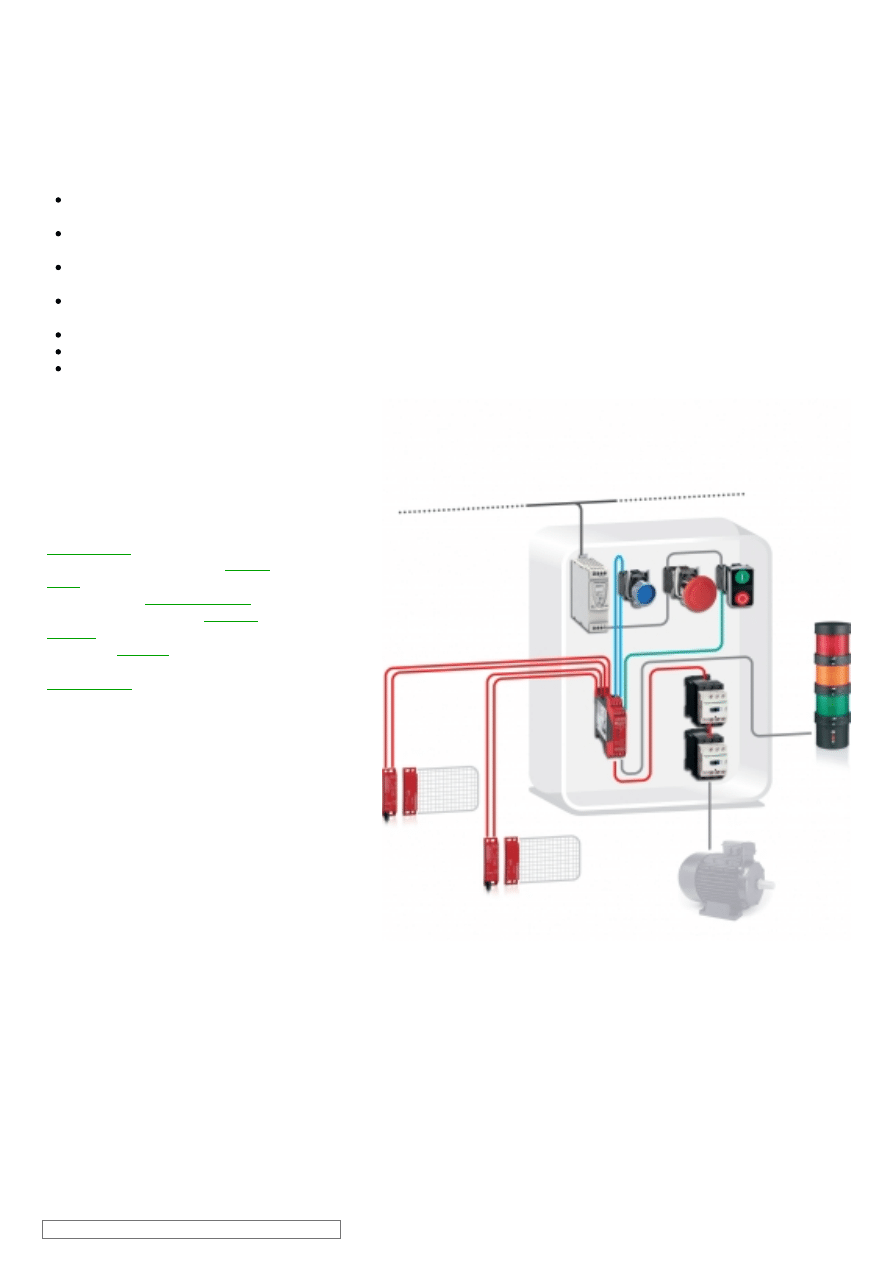
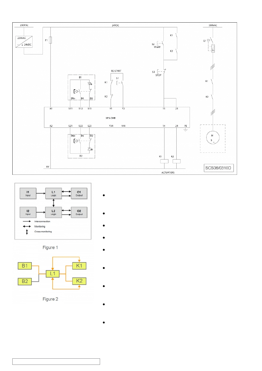
Chain structure:
The circuit diagram SCS06/0310D is a conceptual schematic
diagram and is limited to present the safety function with only the
relevant safety components.
For the designated architecture of the category 4 system, two
redundant channels are implemented.
The circuit arrangement can be divided into three function blocks,
input (I), logic (L) and output (O) blocks, on each channel.
The unbroken lines for monitoring symbolize the higher DCavg
assumed for this category (see figure 1)
Since each protective guard forms part of a dedicated safety
function, the calculation of the performance level considers only
one of them.
The functional channel can be represented by a single guard
switch device (B1) that corresponds to the input block (see figure
2).
The safety module (XPSDMB) corresponds to the logic block
(L1/2), which maintains the internal redundancy of the safety
circuits required for this category.
The output block is represented by two redundant contactors (K1
and K2) that are monitored by the logic block (safety module) to
detect failure.
The complete wiring must be in accordance to EN 60204-1 and
provision to avoid short circuits has to be provided (EN ISO
13849-2 Table D.4).
SCS06/0310 - 03-03-2010
Safety Chain Solution – Magnetic switches
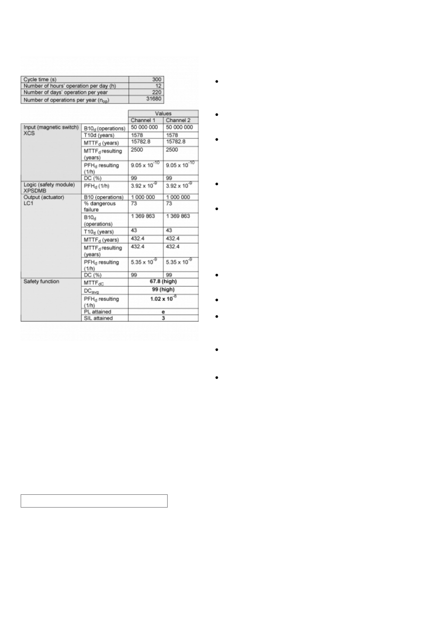
Safety level calculation:
A required performance level (PLr) must be specified for each
intended safety function following a risk evaluation. The
performance level (PL) attained by the control system must be
validated by verifying if it is greater than or equal to the PLr.
If the protective guard device is assumed to be actuated every 5
minutes during 220 working days per year and 12 working hours,
the number of operations (nop) would be 31 680.
A B10d value of 50 000 000 cycles is stated for the coded
magnetic switch. In accordance with the assumed above nop
value, the MTTFd would be 15782.8 years for each channel.
These values are limited to 2500 years in this case as this is the
limit used by the SISTEMA calculation tool for category 4 systems.
A PFHd value of 3.92 x 10
-9
is stated for the safety module
(XPSDMB). This value comes directly from the safety device data
and it is certified by an accepted standards body.
For the redundant contactors K1 and K2, the B10 value
corresponds under nominal load to an electrical lifetime of 1 000
000 switching cycles. If 73% of failures are assumed to be
dangerous, the B10d value is 1 369 863 operations. With the
assumed value for nop, it results in a MTTFd of 432.4 years for
each component. These values are not limited in this case as this
is a category 4 systems and they are under the 2500 year limit
used by the SISTEMA calculation tool.
Measures against common cause failures must attain at least 65
points (i.e. separation (15), diversity (20), over voltage protection
etc. (15) and environmental conditions (25+10)).
Since this is the highest performance level, both the MTTFd of
each channel and the DCavg must be high.
The combination of channel 1 and channel 2 results in a DCavg
99% (high) as we are using magnetic switches with a NO/NC
contact combination, and mirror contact monitoring for the
contactors.
The safety-related control system corresponds to category 4 with
high MTTFd. The complete functional safety chain results in
average probability of dangerous failure (PFHd) of 1.02 x 10
-8.
This corresponds to PL e and SIL 3.
SCS06/0310 - 03-03-2010
ATTENTION
The information provided in this documentation contains general descriptions and/or technical characteristics of the performance of the products contained herein. This
documentation is not intended as a substitute for and is not to be used for determining suitability or reliability of these products for specific user applications.
It is the duty of any such user or integrator to perform the appropriate and complete risk analysis, evaluation and testing of the products with respect to the relevant specific
application or use thereof. Neither Schneider Electric Industries SAS nor any of its affiliates or subsidiaries shall be responsible or liable for misuse of the information
contained herein.
Schneider Electric Industries S.A.S
Head Office
35 rue Joseph Monier
CS 30323
92506 Rueil-Malmaison
www.schneider-electric.com
As standards, specifications and designs change from time to time,
please ask for confirmation of the information given in this publication.
Design : Schneider Electric
Photos : Schneider Electric
Wyszukiwarka
Podobne podstrony:
00 Introduction Safety Chain Solutions disclaimer
12 safety chain solution Safe Stop2 Servo enhanced safety
02 safety chain solution Light curtain
0802 safety chain solution Multifunction Two Hand control
10 safety chain solution Safe stop0 High performance
05 safety chain solution Safety Mat
11 safety chain solution Safe Stop1 High performance
03 safety chain solution Safe Stop0
0402 safety chain solution Safe Stop1 Servo Drive
0401 safety chain solution safe stop1 variable speed drive
0801 safety chain solution Multifunction Safety guard
07 safety chain solution Zero speed detection
01 safety chain solution Motor starter
[2006] Application of Magnetic Energy Recovery Switch (MERS) to Improve Output Power of Wind Turbine
Cwiczenie 06 - Obwody magnetycznie sprzezone
Expoliner Safety 2011 06 09
Cw 03 E 06 Badanie oddziaływania magnetycznego dwóch przewod
Pajak Jan Zaawansowane urzadzenia magnetyczne Tom 06
Aretha Franklin 06 Chain of Fools
więcej podobnych podstron