Safety Chain Solution – Safety Mat
PL d, SIL 2
Allowing frequent controlled access
Function:
Safety-related stop function initiated by any of the safety mats
installed around the different potentially hazardous zones defined
by the dangerous movement of the machine.
The hazardous movement is interrupted either if the emergency
stop device (S1) or any of the safety mats (SM1 or SM2) is
actuated.
Stepping on the safety mat deactivates the safety module
outputs, which results in the switching-off of the motor power
supply by means of the contactors K1 and K2 (stop category 0 in
accordance with EN/IEC 60204-1) in order to prevent possible
hazardous movements or states.
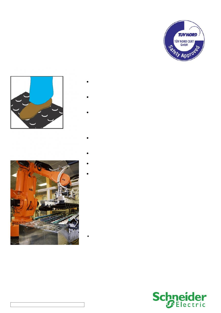
The safety mat provides a protection zone between machine
operator and any dangerous movements and enables free access
for the loading and unloading of the machine.
The safety module monitors the consistent actuation of the
redundant safety mat contacts to detect possible failures.
The main contactors are also monitored by the safety module by
means of the mirror contacts, to detect contact welding.
The resetting of the function can be performed manually or
automatically, depending on the configuration of the safety
module, before renewed start-up of the machine movement.
(*) The function for stopping in an emergency is a protective
measure which complements the safety functions for the
safeguarding of hazardous zones according to EN ISO 12100-2
Typical applications:
Machines which use a free and very frequent access to the hazardous area,
where a high number of interventions are needed.
.
SCS05/0310 - 03-03-2010
Safety Chain Solution – Safety Mat
Design:
The safety function employs well-tried safety principles and is robust in the event of a component failure by means of two
redundant contacts on each safety mat and two redundant contactors (K1 and K2) in the output.
Safety mat failure or contactor fault is detected by the safety module at the next demand upon the safety function or by means of
the restart interlock pushbutton (S4).
The emergency stop device is designed in accordance with EN ISO 13850 and is considered a well-tried component with direct
opening action in accordance with EN/IEC 60947-5-5.
The safety mats must be installed in such a way that it is not possible to access the protected zone without tripping them. They are
electrically inter-connectable without loss of sensitivity and can be butt mounted. They must be used to detect persons having a
weight in accordance with EN ISO13856.
The defined protected area and the minimum distance between the hazardous zone and the detection limit of the device is
calculated in accordance with EN ISO 13855.
The safety module satisfies the requirements for performance level PL e in accordance with EN ISO 13849-1 and SILCL 3 in
accordance with EN/IEC 62061.
Protection against overcurrent must be provided in accordance with EN/IEC 60947-4-1
The contactors (K1 and K2) have mirror contacts in accordance with EN/IEC 60947-4-1, which are integrated into the feedback of
the safety module L1 for contactor fault detection.
The contactors are also considered as well-tried components.
Related products
Switches, pushbuttons, emergency stop -
Switch mode Power supply -
Modular beacon and tower lights -
SCS05/0310 - 03-03-2010
Safety Chain Solution – Safety Mat
Chain structure:
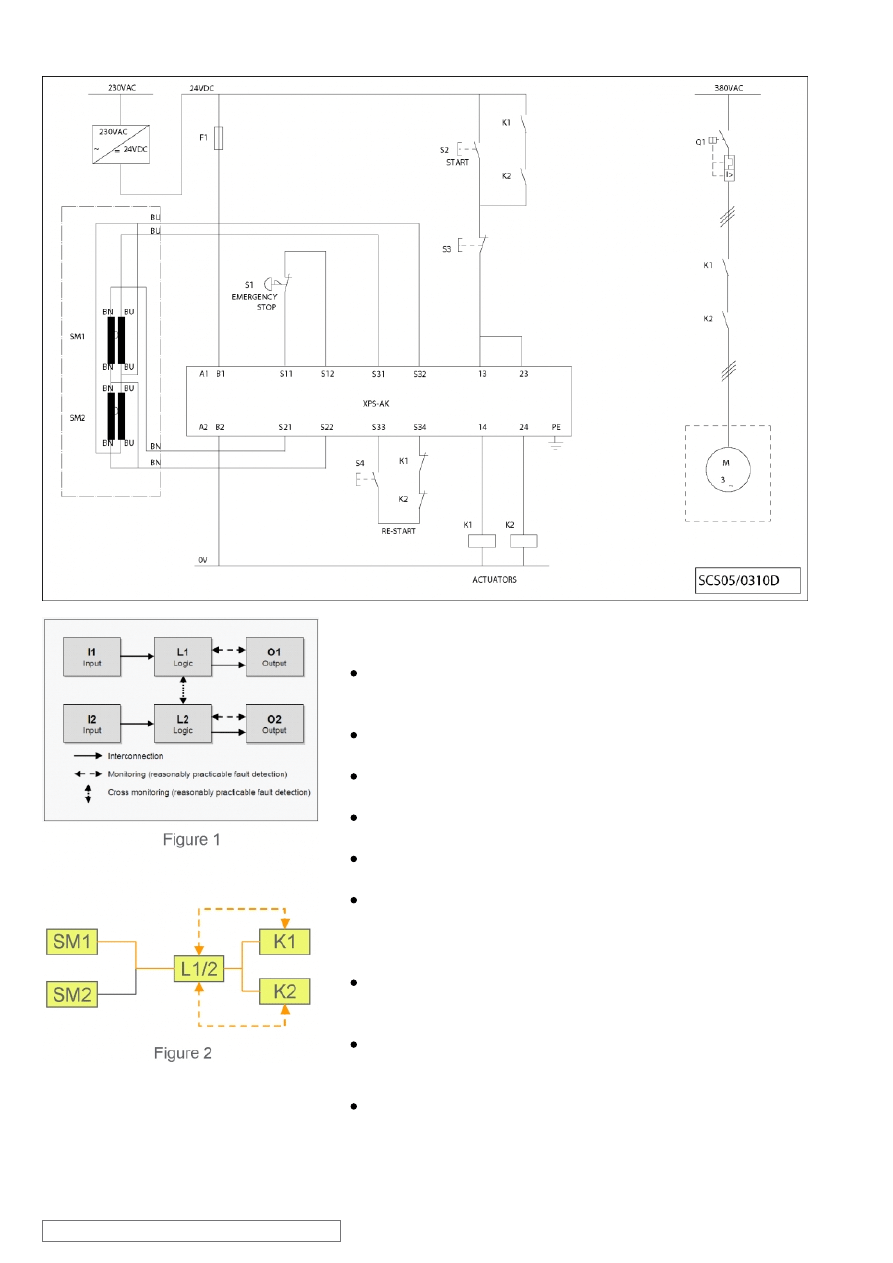
The circuit diagram SCS05/0310D is a conceptual schematic
diagram and is limited to present the safety function with only the
relevant safety components.
For the designated architecture of the category 3 system, two
redundant channels are implemented.
The circuit arrangement can be divided into three function blocks
input (I), logic (L) and output (O) blocks on each channel.
The possibility of fault detection by monitoring the outputs is
indicated by the broken lines (see figure 1).
Since each safety mat triggers a safety function of its own, the
calculation of the performance level considers only one of them.
The functional channel can be represented by a single safety mat
(i.e. SM1) that corresponds to the input block, with two redundant
contacts monitored by the logic block (safety module) to detect
possible failure.
The safety module (XPSAK) corresponds to the logic block
(L1/2), which maintains the internal redundancy of the safety
circuits required for this category.
The output block is represented by two redundant contactors (K1
and K2) that are monitored by the logic block (safety module) to
detect any possible failure.
The complete wiring must be in accordance to EN 60204-1
and the necessary means to avoid short circuits has to be
provided (EN ISO 13849-2 Table D.4).
SCS05/0310 - 03-03-2010
Safety Chain Solution – Safety Mat
Safety level calculation:
A required performance level (PLr) must be specified for each
intended safety function by means of a risk evaluation. The
performance level (PL) attained by the control system must be
validated by verifying if it is greater than or equal to the PLr.
A fault exclusion is assumed for the emergency stop device in
accordance with EN ISO 13849-2, since the maximum number of
switching cycles of these devices is not exceeded within the
mission time (20 years).
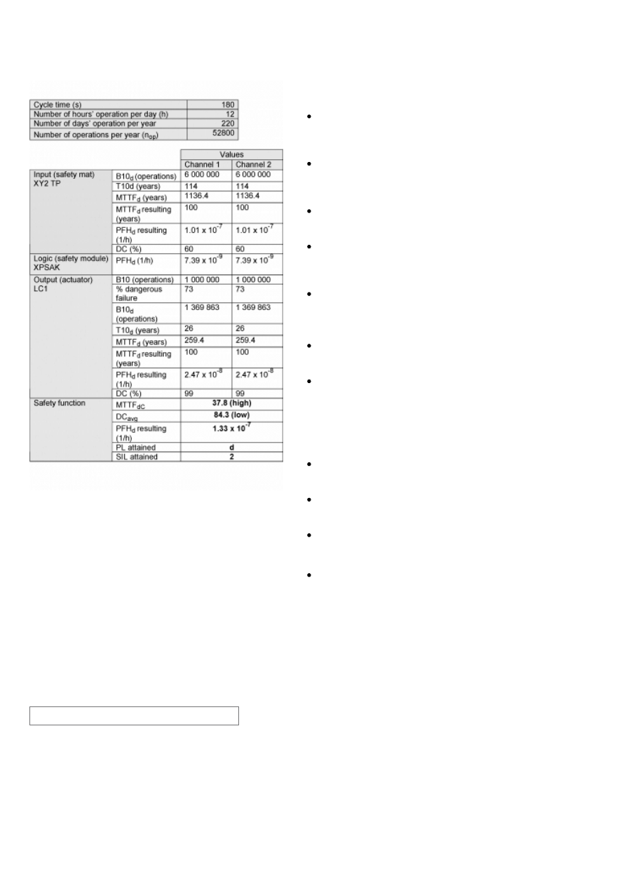
At 220 working days per year, 12 working hours per day and a
cycle time of 3 minutes, the number of operations (nop) would be
52 800.
Mean time to dangerous failure (MTTFd) values exceeding 100
years will be limited to this value in order for the component
reliability not to be overstated in comparison with the other main
influencing variables such as the architecture or tests.
A B10d value of 6 000 000 cycles is stated for the safety mat. In
accordance with the assumed above nop value, the MTTFd would
be 1136.4 years for each channel. These values are therefore
limited to 100 years ("high").
A PFHd value of 7.39 x 10
-9
is stated for the safety module
(XPSAK). This value comes directly from the safety device data
and it is certified by an accepted standards body.
For the redundant contactors K1 and K2, the B10 value
corresponds under nominal load to an electrical lifetime of 1 000
000 switching cycles. If 73% of failures are assumed to be
dangerous, the B10d value is 1 369 863 operations. Using the
assumed value for nop results in a MTTFd of 259.4 years for each
component. These values are therefore limited to 100 years
("high").
Measures against common cause failures (Annex F of EN ISO
13849-1) must attain at least 65 points (i.e. separation (15), over
voltage protection etc. (15) and environmental conditions (25+10)).
The combination of channel 1 and channel 2 results in a DCavg
84.3% (low) as the safety mat can only be monitored for some
characteristics (DC=60%).
The safety-related control system corresponds to category 3 with
high MTTFd. The complete functional safety chain results in
average probability of dangerous failure (PFHd) of 1.33 x 10
-7
.
This corresponds to PL d and SIL 2.
SCS05/0310 - 03-03-2010
ATTENTION
The information provided in this documentation contains general descriptions and/or technical characteristics of the performance of the products contained herein. This
documentation is not intended as a substitute for and is not to be used for determining suitability or reliability of these products for specific user applications.
It is the duty of any such user or integrator to perform the appropriate and complete risk analysis, evaluation and testing of the products with respect to the relevant specific
application or use thereof. Neither Schneider Electric Industries SAS nor any of its affiliates or subsidiaries shall be responsible or liable for misuse of the information
contained herein.
Schneider Electric Industries S.A.S
Head Office
35 rue Joseph Monier
CS 30323
92506 Rueil-Malmaison
www.schneider-electric.com
As standards, specifications and designs change from time to time,
please ask for confirmation of the information given in this publication.
Design : Schneider Electric
Photos : Schneider Electric
Wyszukiwarka
Podobne podstrony:
00 Introduction Safety Chain Solutions disclaimer
12 safety chain solution Safe Stop2 Servo enhanced safety
06 safety chain solution Magnetic switches
02 safety chain solution Light curtain
0802 safety chain solution Multifunction Two Hand control
10 safety chain solution Safe stop0 High performance
11 safety chain solution Safe Stop1 High performance
03 safety chain solution Safe Stop0
0402 safety chain solution Safe Stop1 Servo Drive
0401 safety chain solution safe stop1 variable speed drive
0801 safety chain solution Multifunction Safety guard
07 safety chain solution Zero speed detection
01 safety chain solution Motor starter
new employee safety orientation 1201643571904060 5
Safety net
peace corps safety 2008
#02 SHIPS SAFETY GENERAL
A Surgical Safety Checklist to Reduce Morbidity and Mortality in a Global Population
Safety In Workplace
więcej podobnych podstron