Safety Chain Solution - Light curtain
PL c, SIL 1
Right diagnostic level to achieve increased reliability
Function:
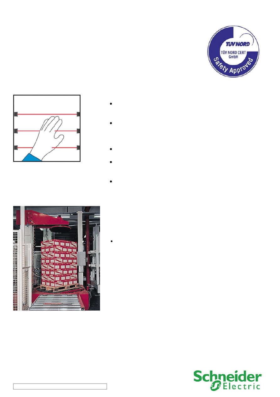
Safety-related stop function initiated by several single-beam
photo-electric devices used as protective equipment (ESPE Type
2 according to EN/IEC 61496-1 and EN/IEC 61496-2).
An interruption of the detection field causes the safety outputs to
open. The deactivation of the safety outputs results in the
switching-off of the motor power supply by means of the contactor
(K1) to help to prevent possible hazardous movements or states
The photo-electric devices (B1...B4) are cyclically tested and
monitored by the safety module to detect possible failures.
A muting function can be enabled by means of photo-electric
sensors (A1, A2). It allows the light curtain's detection function to
be temporary inhibited without triggering the stop function.
During the muting time interval, materials can be transported
through the hazardous area and the muting indicator light (H1)
indicates to the operator this temporary disabling of protection.
Typical applications:
Palletizing stations with automatic control system where pallets would pass
frequently through the hazardous area.
SCS02/0310 - 03-03-2010
Safety Chain Solution - Light curtain
Design:
The safety function employs well-tried safety principles and it is tested periodically by its control system in order to detect failures.
Special photo-electric devices with adequate optical characteristics (aperture angle, extraneous light immunity) in accordance with
EN/IEC 61496-2 are employed.
The access to the hazardous area must be protected by using the four-beam light barrier in consideration of the necessary
mounting height in accordance with EN/IEC TS 62046 and correct positioning with respect to the approach speed of the machine
operator in accordance with EN ISO 13855.
The test rate must be at least 100 X the rate of intrusion into the protected zone.
The safety module satisfies the requirements for performance level PL c in accordance with EN ISO 13849-1 and SILCL 1 in
accordance with EN/IEC 62061.
The start (S2) and the restart interlock (S1) must be located outside the hazardous area and at a point from which the potential
danger is visible.
The muting state must be displayed by an indicator light clearly visible to the operator at the access point to the hazardous area.
The ‘muting' light as well as individual muting sensors are checked directly by the safety module.
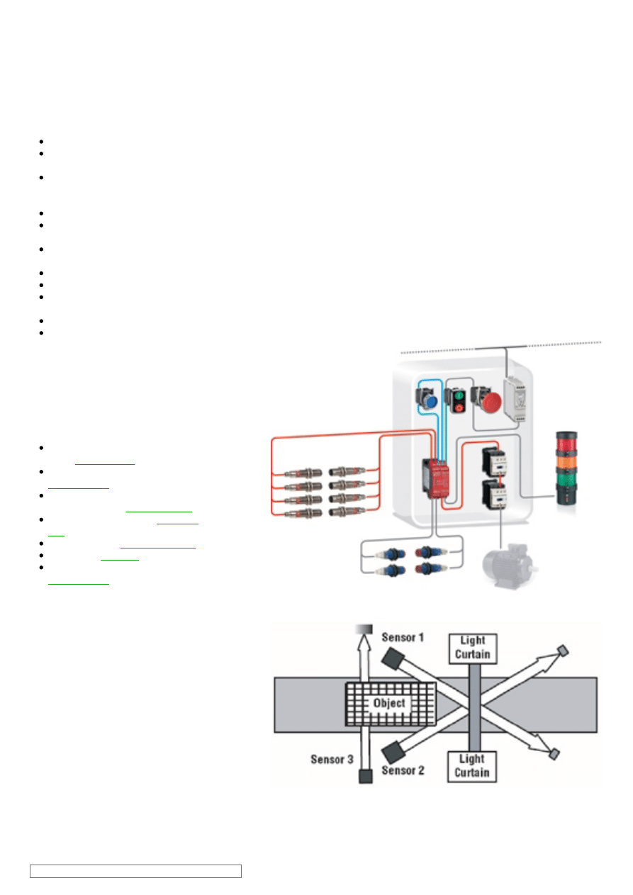
The undetected access of persons through hazardous area during the muting interval must be prevented by the geometrical
arrangement of the muting sensors and the correspondent timing of the control system (see figure 1).
The contactors (K1 and K2) have mirror contacts in accordance with EN/IEC 60947-4-1.
Overcurrent protection must be provided in accordance with EN/IEC 60947-4-1.
Related products
Switches, pushbuttons, emergency
stop -
Switch mode Power supply -
Safety light curtains, single-beam for
body detections -
Modular beacon and tower lights -
SCS02/0310 - 03-03-2010
Safety Chain Solution - Light curtain
Chain structure:
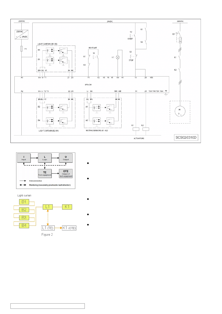
The circuit diagram SCS02/0310D is a conceptual schematic
diagram and is limited to present the safety function with only the
relevant safety components.
For the designated architecture of category 2 the calculation of
the reliability data considers the functional channel having input
(I), logic (L) and output (O) blocks, and indirectly the function
blocks of the test channel (TE).
In this case, the input block represents the single-beam
photo-electric devices (B1 to B4) and the safety module (XPSCM)
corresponds to the logic (L1) and test (TE) blocks.
The output is represented by a contactor (K1) that corresponds to
the test equipment output (see figure 2).
The complete wiring must be in accordance with EN 60204-1 and
measures to avoid short circuits have to be provided (EN ISO
13849-2 Table D.4).
SCS02/0310 - 03-03-2010
Safety Chain Solution - Light curtain
Safety level calculation:
A required performance level (PLr) must be specified for each
intended safety function. The performance level (PL) attained by
the control system must be validated by verifying if it is greater
than or equal to the PLr.
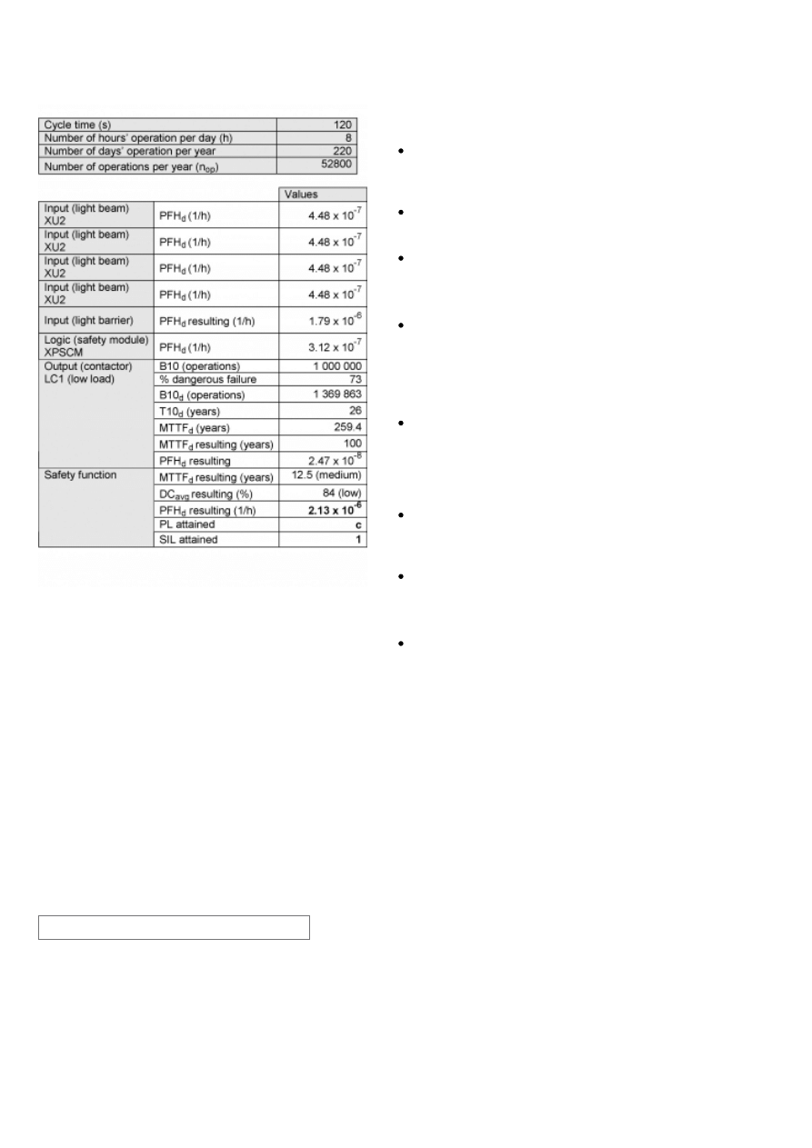
At 220 working days per year, 8 working hours per day and a
cycle time of 120 seconds, the number of operations (nop) would
be 52 800.
Mean time to dangerous failure (MTTFd) values exceeding 100
years will be limited to this value in order for the component
reliability not to be overstated in comparison with the other main
influencing variables such as the architecture or testing.
A PFHd value of 4.48 x 10
-7
is stated for each photo-electric single
beam device (B1 to B4). If we assume 4 beams are used for the
application, then we must use 4 times this value, which results in a
total value of 1.79 x 10
-6
. For the safety module (L1) 3.12 x 10
-7
is
stated. These values come directly from the safety device data
and are certified by an accepted standards body.
For the contactor (K1), the B10 value corresponds under nominal
load to an electrical lifetime of 1 000 000 switching cycles.
If 73% of failures are assumed to be dangerous, the B10d value
is 1 369 863 operations. With the assumed value for nop, it results
in a MTTFd of 259,4 years for K1. This value is therefore limited to
100 years ("high").
Measures against common cause failures (Annex F of EN ISO
13849-1) must attain at least 65 points, i.e. separation (15),
well-tried components (5), over-voltage protection etc. (15) and
environmental conditions (25+10).
The safety-related control system corresponds to category 2 with
medium MTTFd. The complete functional safety chain results in a
DCavg 84 % (low) and average probability of dangerous failure
(PFHd) of 2.13 x 10
-6
per hour.
This corresponds to PL c and SIL 1.
SCS02/0310 - 03-03-2010
ATTENTION
The information provided in this documentation contains general descriptions and/or technical characteristics of the performance of the products contained herein. This
documentation is not intended as a substitute for and is not to be used for determining suitability or reliability of these products for specific user applications.
It is the duty of any such user or integrator to perform the appropriate and complete risk analysis, evaluation and testing of the products with respect to the relevant specific
application or use thereof. Neither Schneider Electric Industries SAS nor any of its affiliates or subsidiaries shall be responsible or liable for misuse of the information
contained herein.
Schneider Electric Industries S.A.S
Head Office
35 rue Joseph Monier
CS 30323
92506 Rueil-Malmaison
www.schneider-electric.com
As standards, specifications and designs change from time to time,
please ask for confirmation of the information given in this publication.
Design : Schneider Electric
Photos : Schneider Electric
Wyszukiwarka
Podobne podstrony:
00 Introduction Safety Chain Solutions disclaimer
12 safety chain solution Safe Stop2 Servo enhanced safety
06 safety chain solution Magnetic switches
0802 safety chain solution Multifunction Two Hand control
10 safety chain solution Safe stop0 High performance
05 safety chain solution Safety Mat
11 safety chain solution Safe Stop1 High performance
03 safety chain solution Safe Stop0
0402 safety chain solution Safe Stop1 Servo Drive
0401 safety chain solution safe stop1 variable speed drive
0801 safety chain solution Multifunction Safety guard
07 safety chain solution Zero speed detection
01 safety chain solution Motor starter
02 Safety Precautions
#02 SHIPS SAFETY GENERAL
02 Bajdor Grabara Green supply chain
Lumiere du monde Light of the World Hymn Światowych Dni Młodzieży Kanada Toronto 02
#02 General Safety
PC Cast Goddess Summoning 02 Goddess of Light (v1 0)
więcej podobnych podstron