Safety Chain Solution – Zero Speed detection
PL e, SIL 3
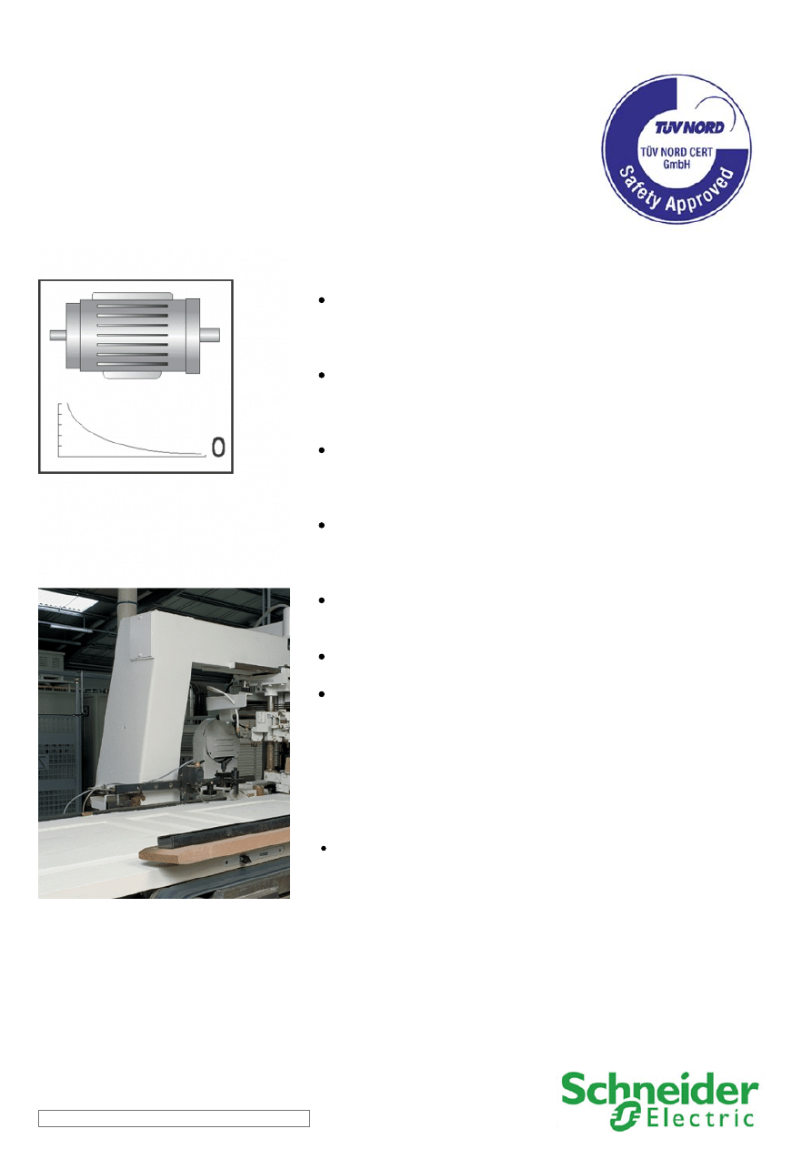
Guarding machines with high inertia
Function:
Safety-related stop function initiated by any stop or emergency
stop command to halt the machine and to unlock the moveable
guard that prevents the access to the hazardous area before the
machine comes to a standstill.
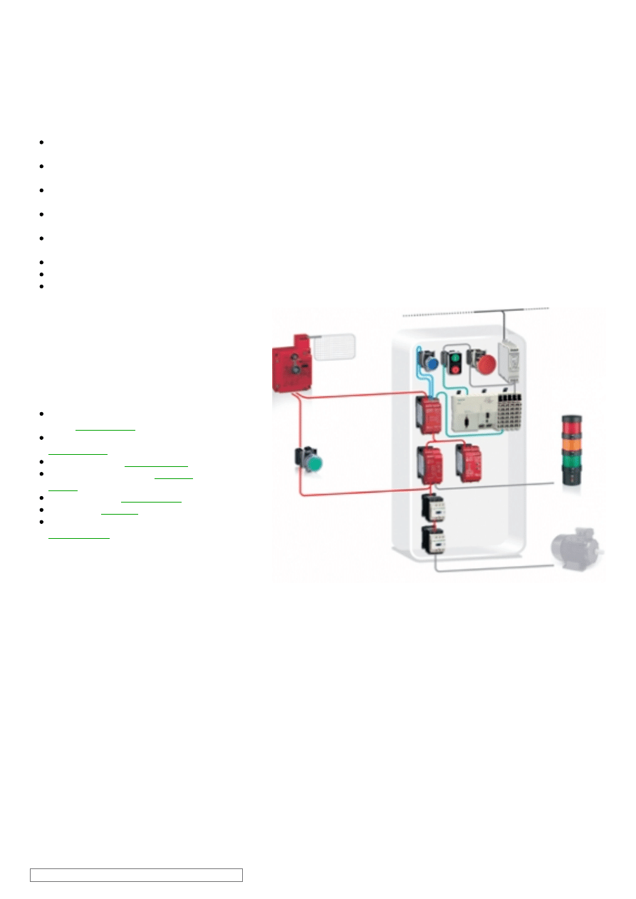
Guard opening is detected by using a solenoid locking interlock
switch in combination with a limit switch in positive actuation
mode, which are then checked by the safety module allowing
detection of the opening or removal of the protective guard.
Actuation of the emergency stop or stop contacts initiates the
functional stopping of the machine by switching-off the motor
power supply. As electric motors run down, a remanent voltage is
produced in the windings of the motor due to residual magnetism.
This voltage is measured so as to detect the stopped condition of
the motor, providing the unlock signal for the electrically locked
movable guard and for engaging brakes after the motor has come
to a standstill.
The continuity of the wiring between the motor windings and the
inputs of the safety module is also monitored to prevent a cable
breakage or fault being seen as a stopped motor
The main contactors are monitored by the safety modules by
means of the mirror contacts to detect e.g. contact welding.
The safety modules also monitor the consistent actuation of the
limit switch contacts to detect failure, before restart of the machine
movement is permitted.
Typical applications:
On metal, wood work or similar high inertia machines with a long run-down of the
hazardous tool movements, and where an electronically interlock guard is used
to protect the hazardous area.
SCS07/0310 - 03-03-2010
Safety Chain Solution – Zero Speed detection
Design:
The safety function employs well-tried safety principles and is robust in the event of a component failure by means of redundant
contacts on the limit switch devices and two redundant contactors (K1 and K2).
The contact synchronization of the limit switches and contactor failure are detected by the safety modules at the next demand on
the safety function.
The start (S4) and the restart interlock (S2) pushbutton must be located outside the hazardous area and at a point from which the
potential danger is visible.
The safety modules satisfy thel requirements for performance level PL e in accordance with EN ISO 13849-1 and SILCL 3 in
accordance with EN/IEC 62061.
The adjustable switching threshold in the safety module must be selected so that under the most unfavourable operating
conditions, the machine movements will stop before the guard is unlocked.
The contactors (K1 and K2) are considered as well-tried components.
Protection against overcurrent must be provided in accordance with EN/IEC 60947-4-1.
The contactors (K1 and K2) have mirror contacts in accordance with EN/IEC 60947-4-1, which are integrated into the feedback of
the safety modules for contactor fault detection.
Related products
Switches, pushbuttons, emergency
stop -
Switch mode Power supply -
Guard interlock switch -
Contactor -
Modular beacon and tower lights -
SCS07/0310 - 03-03-2010
Safety Chain Solution – Zero Speed detection
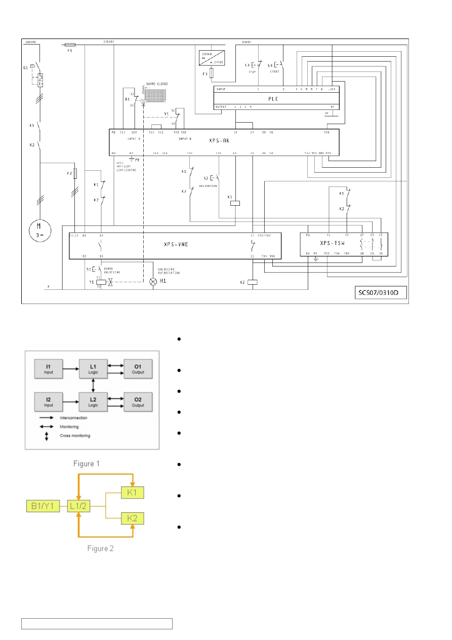
Chain structure:
The circuit diagram SCS07/0310D is a conceptual schematic
diagram and is limited to present the safety function with only the
relevant safety components.
For the designated architecture of the category 4 system, two
redundant channels are implemented.
The circuit arrangement can be divided into two channels with the
input (I), logic (L) and output (O) blocks on each channel.
The unbroken lines for monitoring symbolize the higher DCavg
assumed for this category (see figure 1).
The functional channel is represented by the moveable guard
switch device (B1/Y1) that would correspond to the input block
(see figure 2).
The safety module (XPSAK) correspond to the logic block
(L1/L2), which maintains the internal redundancy of the safety
circuits required for this category.
The output block is represented by two redundant contactors (K1
and K2) that are monitored by the logic block (safety modules) to
detect any failure.
The complete wiring must be in accordance to EN 60204-1
and the necessary means to avoid short circuits has to be
provided (EN ISO 13849-2 Table D.4).
SCS07/0310 - 03-03-2010
Safety Chain Solution – Zero Speed detection
Safety level calculation:
A required performance level (PLr) must be specified for each
intended safety function following a risk evaluation. The
performance level (PL) attained by the control system must be
validated by verifying if it is greater than or equal to the PLr.
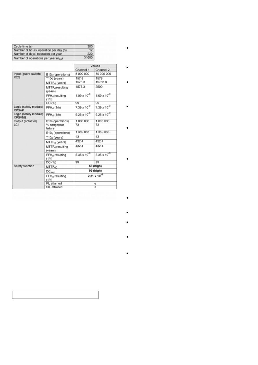
If the protective guard is assumed to be actuated every 5 minutes
during 220 working days per year and 12 working hours, the
number of operations (nop) would be 31 680.
A B10d value of 5 000 000 cycles is stated for the solenoid
locking switch. In accordance with the assumed above nop value,
the MTTFd would be 1578.3 years for channel 1. These values are
not limited in this case as this is a category 4 system and they are
under the 2500 year limit used by the SISTEMA calculation tool.
A B10d value of 50 000 000 cycles is stated for the limit switch. In
accordance with the assumed nop value, the MTTFd would be
15782.8 years for channel 2. This value is limited to 2500 years for
this case as this is a category 4 system.
A PFHd value of 7.39 x 10
-9
is stated for the first safety module
(XPSAK) and a value of 9.26 x 10
-9
is stated for the second safety
module. As they are in series in the safety chain, both must be
added for the total calculation. These values come directly from
the safety device data and are certified by an accepted standards
body.
For the redundant contactors K1 and K2, the B10 value
corresponds under nominal load to an electrical lifetime of 1 000
000 switching cycles. If 73% of failures are assumed to be
dangerous, the B10d values is 1 369 863 operations. With the
assumed value for nop, it results in a MTTFd of 432.4 years for
each component. These values are not limited in this case as this
is a category 4 system and they are under the 2500 year limit of
SISTEMA calculation tool.
Measures against common cause failures must attained at least
65 points (i.e. separation (15), diversity (20), over voltage
protection etc. (15) and environmental conditions (25+10)).
Since this is the highest performance level, both the MTTFd of
each channel and the DCavg must be high.
The combination of channel 1 and channel 2 results in a DCavg
99% (high) as we are monitoring the combination of guard switch
contacts and using mirror contact monitoring for the contactors.
The safety-related control system corresponds to category 4 with
high MTTFd. The complete functional safety chain results in an
average probability of dangerous failure (PFHd) of 2.31 x 10
-8
.
This corresponds to PL e and SIL 3.
SCS07/0310 - 03-03-2010
ATTENTION
The information provided in this documentation contains general descriptions and/or technical characteristics of the performance of the products contained herein. This
documentation is not intended as a substitute for and is not to be used for determining suitability or reliability of these products for specific user applications.
It is the duty of any such user or integrator to perform the appropriate and complete risk analysis, evaluation and testing of the products with respect to the relevant specific
application or use thereof. Neither Schneider Electric Industries SAS nor any of its affiliates or subsidiaries shall be responsible or liable for misuse of the information
contained herein.
Schneider Electric Industries S.A.S
Head Office
35 rue Joseph Monier
CS 30323
92506 Rueil-Malmaison
www.schneider-electric.com
As standards, specifications and designs change from time to time,
please ask for confirmation of the information given in this publication.
Design : Schneider Electric
Photos : Schneider Electric
Wyszukiwarka
Podobne podstrony:
0401 safety chain solution safe stop1 variable speed drive
00 Introduction Safety Chain Solutions disclaimer
12 safety chain solution Safe Stop2 Servo enhanced safety
06 safety chain solution Magnetic switches
02 safety chain solution Light curtain
0802 safety chain solution Multifunction Two Hand control
10 safety chain solution Safe stop0 High performance
05 safety chain solution Safety Mat
11 safety chain solution Safe Stop1 High performance
03 safety chain solution Safe Stop0
0402 safety chain solution Safe Stop1 Servo Drive
0801 safety chain solution Multifunction Safety guard
01 safety chain solution Motor starter
AVR182 Zero Cross Detector en
AVR182 Zero Cross Detector pl i Nieznany (2)
AVR205 Zero Cross Detector en i Nieznany (2)
2003 07 supply chain challenges
więcej podobnych podstron