Safety Chain Solution – Safe Stop 1 – High
performance
PL e, SIL 3
Safety integrated devices for an easier chain
configuration
Function:
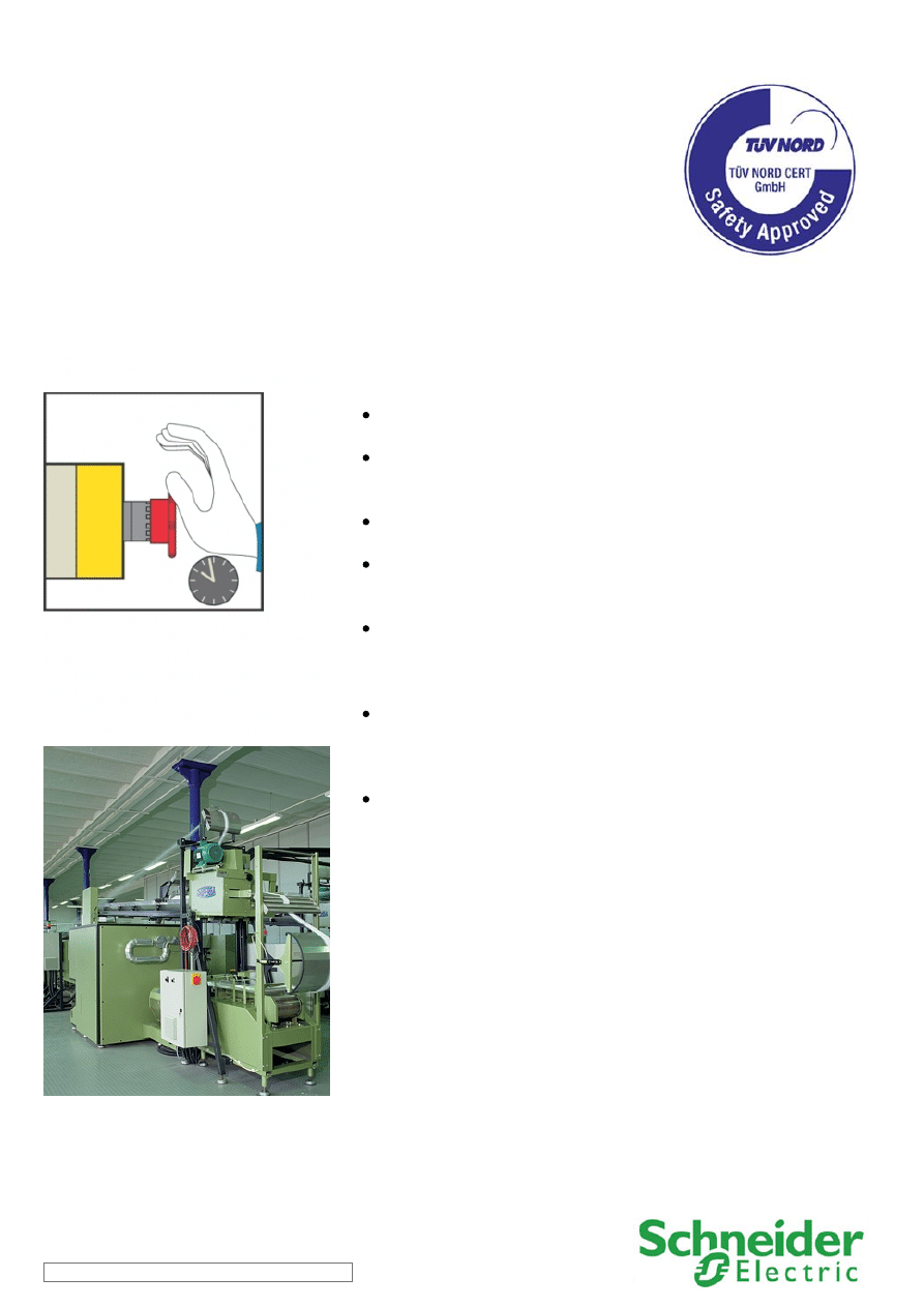
Safety-related stop function initiated by a moveable guard that
help protects access to the hazardous area.
Controlled stopping with power maintained to the actuator (drive)
to achieve stopping (i.e. braking), then cut-off of power when
standstill is reached (Safe Stop 1).
The hazardous movement is interrupted either if the stop button
(S2) or the emergency stop device (S3) is actuated.
Opening of this guard is detected by a magnetic switch, which
initiates the functional stopping of the drive, i.e. by a braking ramp
(stop category 1 in accordance with EN/IEC 60204-1).
After the delay time monitored by the safety module has elapsed,
the safety delayed outputs are deactivated. The drive is then
halted, by the ‘safe torque off‘ (STO) safety function integrated
within it, which prevents the motor from restarting unintentionally.
The switching of the STO and LI3 input is monitored by the drive.
The power stage is disabled if the time offset is exceeded. The
motor can no longer generate torque and coasts down without
braking.
The safety module also monitors the consistent actuation of the
redundant coded magnetic switch contacts to detect possible
failure, before restart of the machine movement is permitted.
Typical applications:
Machines that use drives in their movements due to high speed and precision
needed (i.e. textile, wood-working or simple packaging machines), when the delayed
initiation of the stopping in the event of a fault must not involve an unacceptably high
residual risk.
SCS11/0311 - 17-03-2011
Safety Chain Solution – Safe Stop 1 – High
performance
Design:
The safety function employs well-tried safety principles and is robust in the event of a component failure by means of two
redundant contacts on the magnetic switch device and two redundant internal circuits for the drive safety function.
The contact failure of the magnetic switch is detected by the safety module at the next demand upon the safety function.
The safety module satisfies the requirements for performance level up to PL e in accordance with EN ISO 13849-1 and SILCL 3 in
accordance with EN/IEC 62061 for the safety delayed outputs.
The adjustable braking time in the safety module must be selected so that under the most unfavorable operating conditions, the
machine's movement is stopped before power is removed from the drive.
Protection against over-current must be provided in accordance with EN/IEC 60947-4-1.
The variable speed drive can be installed directly as part of the safety chain of the safety-related control system as it features an
integrated safety function (Safe torque off - STO), which is designed to ensure a motor stop and prevent accidental restart.
The STO function meets the requirements of category 4 and PL e of EN ISO 13849-1, SIL 3 in accordance with EN/IEC 61508 and
the standard dealing with the functional safety requirements of power drive systems EN/IEC 61800-5-2.
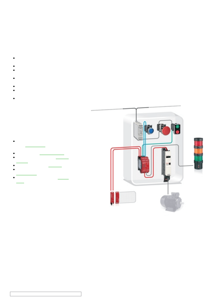
Related products
Switches, pushbuttons, emergency
stop -
Coded magnetic switches -
Modular beacon and tower lights -
SCS11/0311 - 17-03-2011
Safety Chain Solution – Safe Stop 1 – High
performance
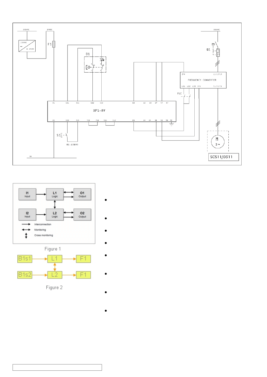
Chain structure:
The circuit diagram SCS11/0311D is a conceptual schematic
diagram and is limited to present the safety function with only the
relevant safety components.
For the designated architecture of category 4, two redundant
channels are implemented.
The circuit arrangement can be divided into three function blocks,
input (I), logic (L) and output (O) blocks, per channel.
The unbroken lines for monitoring symbolize the higher DCavg
assumed for this category (see figure 1).
The functional channel is represented by the magnetic switch
device (B1) that correspond to the input part by means of two
switches s1 and s2 (see figure 2).
The safety module (XPSAV) corresponds to the logic block
(L1/L2), which maintains the internal redundancy of the safety
circuits required for this architecture.
The output block is represented by the drive (F1) with two
redundant internal circuits related to the integrated ‘safe torque
off' safety function (STO/LI3)
The complete wiring must be in accordance to EN 60204-1 and
the necessary means to avoid short circuits has to be provided
(EN ISO 13849-2 Table D.4).
SCS11/0311 - 17-03-2011
Safety Chain Solution – Safe Stop 1 – High
performance
Safety level calculation:
A required performance level (PLr) must be specified for each
intended safety function following a risk evaluation. The
performance level (PL) attained by the control system must be
validated by verifying if it is greater than or equal to the PLr.
Mean time to dangerous failure (MTTFd) values exceeding 100
years are limited to this value in order for the component reliability
not to be overstated in comparison with the other main influencing
variables such as the architecture or tests.
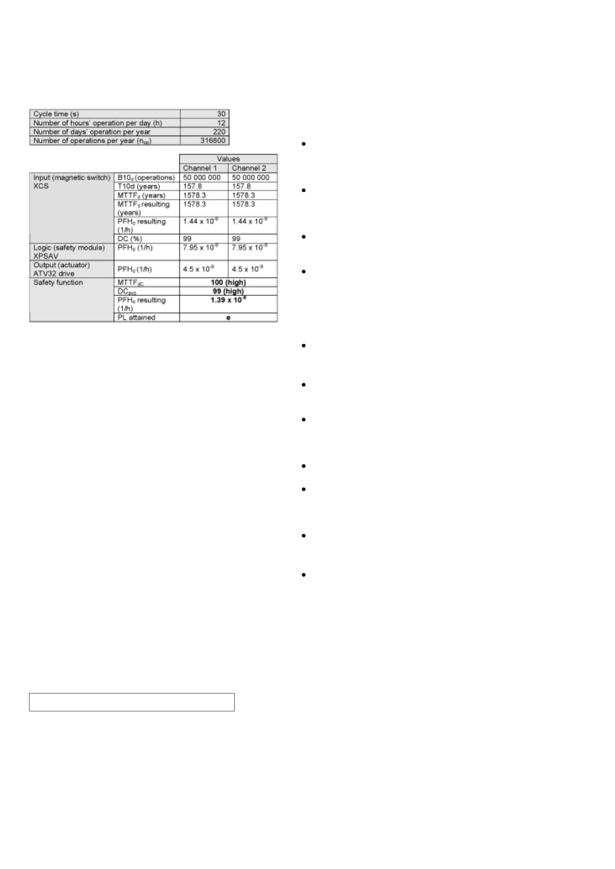
If the protective guard device is assumed to be actuated every half
minute during 220 working days per year and 12 working hours,
the number of operations (nop) would be 316 800.
A B10d value of 50 000 000 cycles is stated for the coded
magnetic switch. In accordance with the assumed above nop
value, the MTTFd would be 1578.3 years for each channel. These
values are not limited in this case as this is category 4 system and
they are under the 2500 year limit used by the SISTEMA
calculation tool.
A PFHd value of 7.95 x 10
-9
is stated for the safety module
(XPSAV). This value comes directly from the safety device data
and is certified by an accepted standards body.
For the variable speed drive a PFHd value of 4.5 x 10
-8
is stated.
This value comes directly from the device data and it is certified by
an accepted standards body.
Measures against common cause failures (Annex F of EN ISO
13849-1) must attain at least 65 points (i.e. separation of wiring
(15), overvoltage protection etc. (15) and environmental conditions
(25+10).
Since this is the highest performance level, both the MTTFd of
each channel and the DCavg must be high.
The combination of channel 1 and channel 2 results in a DCavg >
99 % (high) as we are monitoring the coded magnetic switch input
contacts as well as the STO and LI3 input synchronization on the
drive.
The safety-related control system corresponds to category 4 with
high MTTFd (> 30). The complete functional safety chain results in
average probability of dangerous failure (PFHd) of 1.39 x 10
-8
.
This corresponds to PL e and SIL 3.
SCS11/0311 - 17-03-2011
ATTENTION
The information provided in this documentation contains general descriptions and/or technical characteristics of the performance of the products contained herein. This
documentation is not intended as a substitute for and is not to be used for determining suitability or reliability of these products for specific user applications.
It is the duty of any such user or integrator to perform the appropriate and complete risk analysis, evaluation and testing of the products with respect to the relevant specific
application or use thereof. Neither Schneider Electric Industries SAS nor any of its affiliates or subsidiaries shall be responsible or liable for misuse of the information
contained herein.
Schneider Electric Industries S.A.S
Head Office
35 rue Joseph Monier
CS 30323
92506 Rueil-Malmaison
www.schneider-electric.com
As standards, specifications and designs change from time to time,
please ask for confirmation of the information given in this publication.
Design : Schneider Electric
Photos : Schneider Electric
Wyszukiwarka
Podobne podstrony:
10 safety chain solution Safe stop0 High performance
0402 safety chain solution Safe Stop1 Servo Drive
0401 safety chain solution safe stop1 variable speed drive
12 safety chain solution Safe Stop2 Servo enhanced safety
03 safety chain solution Safe Stop0
00 Introduction Safety Chain Solutions disclaimer
06 safety chain solution Magnetic switches
02 safety chain solution Light curtain
0802 safety chain solution Multifunction Two Hand control
05 safety chain solution Safety Mat
0801 safety chain solution Multifunction Safety guard
07 safety chain solution Zero speed detection
01 safety chain solution Motor starter
A Novel High Performance Utility Interactive Photovoltaic Inverter System
High Performance Fibers
Method Development in High Performance Liquid Chromatography
A Novel High Performance Utility Interactive Photovoltaic Inverter System
High Performance Context Free Parser for Polymorphic Malware Detection
więcej podobnych podstron