U S E R ’ S G U I D E
Final Mix
™
™
®
Plug-in for Mackie Digital Mixers
™
2
Acuma Final Mix
Iconography
“Mackie” and the “Running Man” figure are trademarks or
registered trademarks of Mackie Designs Inc. All other brand
names mentioned are trademarks or registered trademarks of
their respective holders, and are hereby acknowledged.
Part No. 0000815
Rev. 5 12/2001
© 2001 Mackie Designs Inc. All Rights Reserved.
This icon identifies a description of how to
perform an action with the mouse.
This icon identifies a description of how to
perform an action from the console.
This icon will lead you to some further
explanations of features and practical tips.
This icon marks information that is very
important, so please make sure you have a read.
This icon does not appear in this guide.
Note:
Note:
Note:
Note:
Note: Any future revisions of this guide will be available for viewing and
downloading from our website: www.mackie.com.
Further plug-in details and preset downloads can be obtained from
www.acumalabs.com.

User’s Guide
3
Contents
Iconography ----------------------------------------------------- 2
Introduction ----------------------------------------4
About Acuma Labs (www.acumalabs.com) ----------------4
About Final Mix ------------------------------------------------- 5
About the D8B UFX Card -------------------------------------- 5
Main Features ------------------------------------- 6
Let’s Get Started ----------------------------------- 7
Requirements ---------------------------------------------------- 7
Using Final Mix ------------------------------------ 8
Front Panel Overview ----------------------------------------- 8
Pre/Post Equalizers (Six-band) ---------------------------- 10
Dynamics - Crossovers/Keying Graph --------------------- 13
Dynamics Processing ------------------------------------ 16
Contour Edit Screen -------------------------------------- 17
Node Editing ----------------------------------------------- 21
Other Controls in the Dynamics Section ------------ 22
Global Controls Block --------------------------------------- 24
4
Acuma Final Mix
Introduction
Thank you for purchasing Acuma Labs’ Final Mix stereo
mastering plug-in, one of the exciting members of the new family
of 24-bit plug-ins for the D8B. Final Mix has been specifically
designed for the new Mackie Universal Effects (UFX) card.
Final Mix is a professional stereo mastering plug-in for the
Mackie D8B that offers multi-band dynamics processing and
equalization. It has three individual dynamics processors, each
with its own set of controls and selectable crossover points. It
also has two separate six-band parametric eqs, one located
before the dynamics section, and the other after. Each dynamics
band is typically used as a compressor, but expansion is also
possible. An intuitive dynamics contour edit screen providess
easy setup of your compressor parameters and allows you to
draw in the perfect soft knee curve. Final Mix also offers a
simple to use noise gate and a soft-clip limiter. With intuitive
screens and controls, Final Mix promises to be one of your most
invaluable tools. It can take your D8B projects to new heights.
About Acuma Labs (www.acumalabs.com)
Acuma Labs develops real-time embedded systems for
professional audio applications to create high-quality products
for the music and pro-audio industries. Acuma specializes in
digital audio effects using DSP, real-time operating systems,
graphical user interfaces, and digital hardware design.

User’s Guide
5
About Final Mix
Mastering is often the element that separates a good production
from a great one. Acuma Labs’ Final Mix enables you to master
your session within the D8B and print directly to hard disk or
DAT. All this without having to rely on expensive mastering
houses or outboard gear. Settings can be saved as part of your
session! Final Mix features six-band parametric (pre-dynamics)
equalizer, multi-band compression, and a six-band parametric
(post-dynamics) equalizer—12 bands of stereo EQ in all. All
settings are easily edited using drag and drop to create perfect
EQ curves and compression settings. All three dynamics bands
feature individual threshold, attack, and release times. A
graphical contour edit screen for each dynamics band allows you
to easily set a desired ratio. Then you can create your own hard
knee or soft knee, or even draw in an expander curve. Each
dynamics band features its own key filter. This allows you to
emphasize or de-emphasize a portion of the signal within the
band. The Soft-Clip feature adds a smooth, analog-style clip
response when your signal gets close to overload. Other features
such as Noise Gate and Band Linking ensure that Final Mix will
be an integral part of your mixes from here out.
Note: Earlier D8Bs were fitted with 16 MB of memory. It is recommended that
you increase this to 32 MB (as fitted in newer D8Bs) if you install more than one
UFX card. Memory upgrade instructions are supplied with each UFX card.
About the D8B UFX Card
The Mackie UFX card provides robust processing power for
computation-heavy plug-ins. The UFX card is a 4-in/4-out
architecture, which means it can support four mono, two mono
and one stereo, or two stereo sends simultaneously. Up to four
UFX cards can be installed in the D8B, allowing up to sixteen
simultaneous single-channel effects, eight stereo plug-ins, or
combinations thereof.

6
Acuma Final Mix
Main Features
• Stereo mastering plug-in solution for the D8B
• 6-band pre-dynamics parametric equalizer
• 3-band dynamics processor
• 6-band post-dynamics parametric equalizer
• Noise gate
• Soft-Clip feature to provide peak overload protection
• DC removal filter
• On-screen help (via the question mark (?) button)
• Dynamics auto make-up gain
• Individual key selector for each dynamics band
• Graphical, user definable dynamics band contours
• Adjustable crossover points and slopes for multi-band dynamics
• Linking of dynamics band edits
• All controls full stereo with the exception of input and
output levels
• Fully automated
• Global enable button
• On/Off for the dynamics section and each EQ
• On/Off for each EQ and dynamics band
• Mute for each dynamics band to assist with crossover setup
• Separate dynamics and EQ reset buttons
• Plug-in patch load and save
• Memories A and B for quick comparisons
• Input, output, and gain reduction metering

User’s Guide
7
Requirements
• One or more Mackie UFX cards
• Mackie Real Time OS 3.0 Software
• Plug-in Software
We will assume you have successfully installed a Mackie UFX
card and Mackie Real Time OS 3.0 software upgrade. If you have
encountered problems with the installation of hardware or
software, please see their associated user guides or contact
Mackie support (www.mackie.com).
Please see the Licensing section of the Digital 8•Bus version 3.0
owner’s manual for information on both authorizing the plug-in,
and the unlock procedure.
Please see Appendix C of the Digital 8•Bus version 3.0 owner’s
manual for information on configuring the plug-in.
Let’s Get Started
8
Acuma Final Mix
Using Final Mix
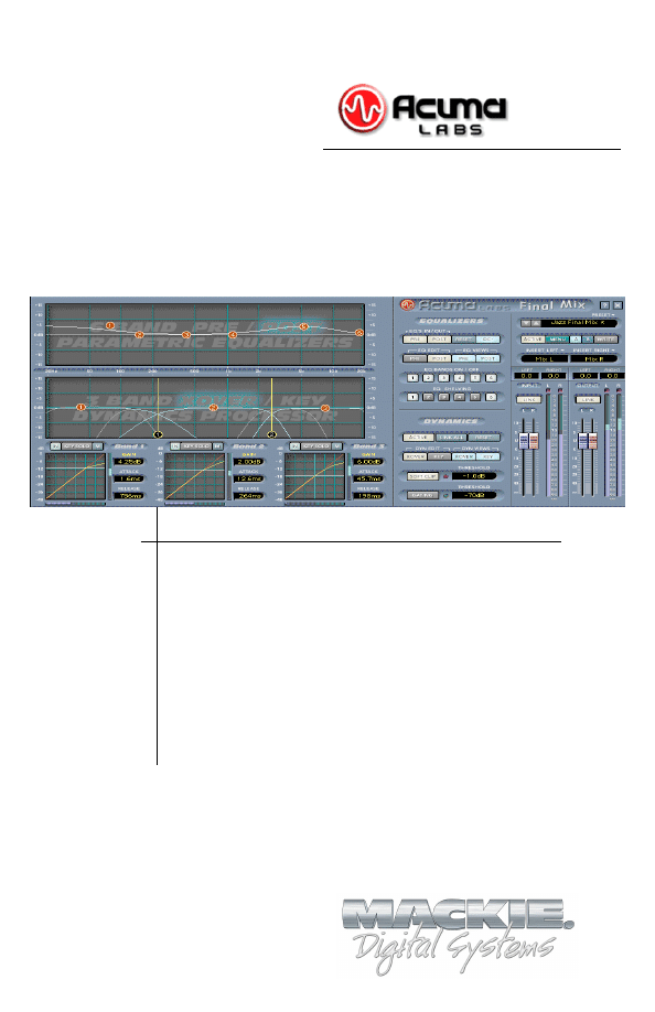
Front Panel Overview
You can think of Final Mix as being broken into three basic blocks.
The dynamics and equalizer blocks have alternate pop-up screens
that can be accessed for a closer look and detailed editing.
Pre/Post Equalizers (Six Band)
Global Controls
Dynamics Crossover/Key
Pre/Post Equalizers (Six-band) Block (see page 10)
The equalizer block is comprised of two separate six-band
parametric equalizers. One is pre-dynamics processing and the
other is post dynamics. Each offers a visual representation of your
EQ curves that can be viewed together or separately on one
convenient screen. Each of the six EQ bands is represented by a
colored node (or ball). Each node has independent gain, frequency,
Q, and filter type (shelf or bandpass) controls. Control-click sets a
selected node to its default value. Right-clicking allows editing of
the Q rather than the frequency. Double-clicking on the EQ screen
brings up the parameter window. This allows you to view and adjust
the numeric values of each band independently.

User’s Guide
9
Dynamics Crossover/Key Block (see page 13)
This screen allows you to view and edit the crossovers and key
filters. The crossover is used to split the signal into three
individual bands, each of which is then sent to its own dynamics
processor. In Final Mix each of the three dynamics bands has its
own adjustable key filter. This can be used to emphasize or de-
emphasize the compression within each band. From the crossover/
key setup screen you can drag and drop nodes to adjust crossover
points and key parameters. Each band has an individual IN/OUT
button to enable or disable dynamics processing for the band. Each
band also has a mute button, which is useful for allowing you to
listen to exactly what the crossover is doing. By muting all but one
band at a time you can solo the band. Similarly, each key filter has
its own KEY SOLO button that lets you solo the key signals.
Double-clicking anywhere on the crossover screen opens another
editing window. This window displays numeric values of the
crossover frequencies, slopes, key gains, frequency centers, and
bandwidths.
At the bottom of the dynamics block, there are three small
windows. These show an overview of the dynamics contours, as
well as the attacks, releases, and gains, of the three dynamics
bands. Double-clicking on any of the smaller contour screens
brings up the corresponding larger screen for detailed editing of
the contour. The contour allows you to control the threshold and
ratio, as well as a desired knee. It is a view of the overall ‘shape’
or contour of exactly what the compressor is going to do your
signal. You can even draw in regions of expansion. For more
information see the Dynamics Processing section, later in this
manual. From this screen you can also enable or disable the band’s
auto make-up gain. Band View displays the edit screen of a
selected band along with numeric windows that display makeup
gain, attack, and release values.
Global Controls Block (see page 24)
The global block contains all of Final Mix’s global assignments.
These assignments include Preset Toggle Control, Preset Title
Window, ACTIVE, MENU, Mem A/B, WRITE, LEFT/RIGHT
INSERTS, and Fader LINK. There are also Input and Output
faders, and Meters. Note that there is also a help button, marked
with a question mark (?), in the top right corner of this section.
10
Acuma Final Mix
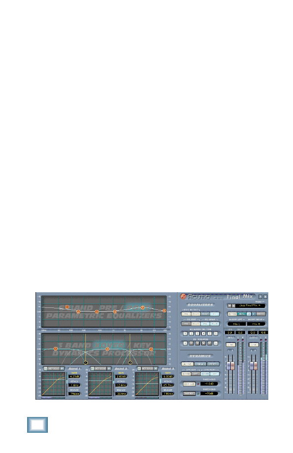
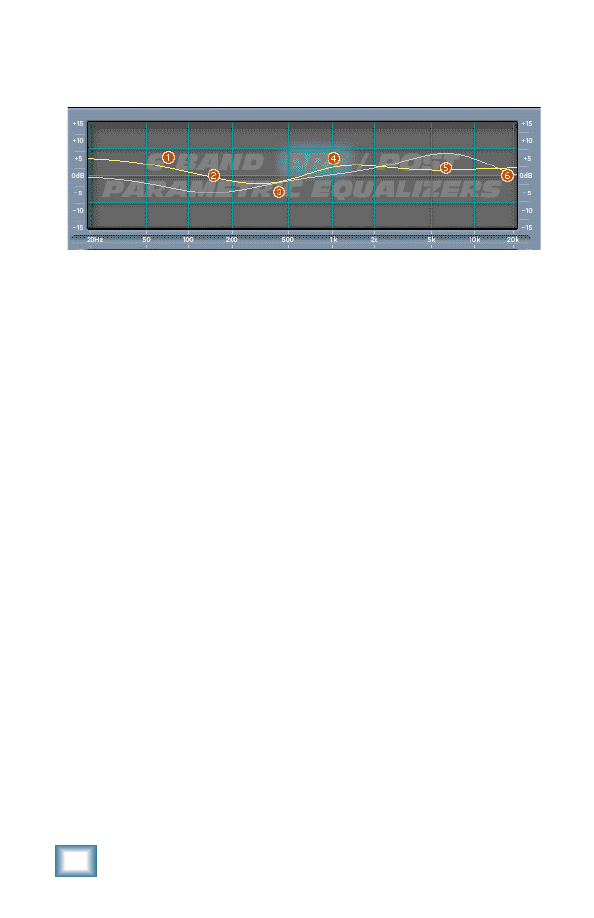
Pre/Post Equalizers (Six-band)
Pre and Post Equalizer graphs
The main EQ graph allows you to display and edit both the Pre
and Post EQ. Note that Pre and Post refer to where the EQs
occur in the signal processing path. You can see a block diagram
of this path by clicking on the question mark (?) on the top right
corner of the Final Mix main screen.
There are four buttons that allow you to select what you view
and what you edit. These are the PRE and POST EQ EDIT, and
PRE and POST EQ VIEW buttons. They are located just to the
right of the main graph display. The EQ screen defaults to PRE
EQ-ON when Final Mix is initially activated. PRE EQ-ON is also
indicated by the letters (PRE) that are highlighted on the
background screen. To toggle between which EQ curve you are
editing, use the EQ EDIT PRE and POST selector buttons. You
can only edit either the Pre or Post EQ at one time, although you
can view both depending on which EQ views are active. Turn the
views on and off with the EQ VIEWS buttons.
EQ Editing
Six nodes (balls) are displayed for each of the Pre and Post EQ
curves. Each node on a selected curve offers independent gain,
frequency and Q control. To adjust EQ curves, simply drag
individual bands (nodes) by grabbing a ball with your left mouse
button. Move it up and down to adjust the gain or to the left and
right to adjust frequency. The Q of each band can be adjusted by
right-clicking on a node and moving it to the left and right.
Control-click sets a selected node to its default value.
User’s Guide
11
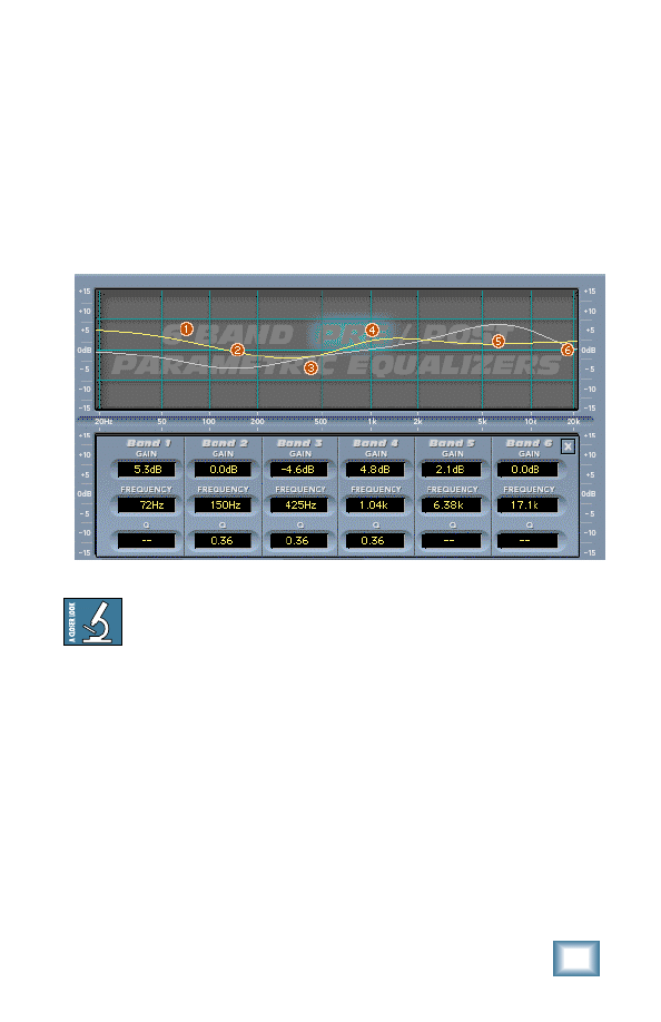
EQ Values Panel
Double-clicking anywhere on the EQ screen brings up the EQ
Values Screen (see below). This shows the gain, frequency and Q
corresponding to either the Pre or Post EQ. Which is shown
depends on which of these is selected for editing (by the EQ EDIT
PRE/POST buttons). EQ bands can also be adjusted from this
screen using the mouse to click on a window and scroll the
numeric values up or down. You can also use the up and down
arrows on your keyboard to nudge the parameter a small amount.
EQ Values screen
Achieving the right amount of compression can change an
EQ of a signal. For this reason, it’s handy to have post
compression EQ. The changes that are made in the Post EQ
can be used to rebalance the overall EQ of your mix.
If you find that the display is too hard to see, try turning off
either PRE or POST buttons so that only one is lit. These
are labeled as EQ VIEWS in the Equalizer status screen.
This allows you to view one curve at a time.
Try changing the curve by using your mouse to drag
individual nodes, or by adjusting values from the EQ Values
Screen.
If you are not using the dynamics section of Final Mix, the
Pre and Post EQs cascade together to give you a 12-band
parametric EQ.

12
Acuma Final Mix
DC
DC stands for DC offset. This is a filter that automatically
removes DC offset noise that is unwanted when you are at the
mastering stage. The default state is on when you activate Final
Mix. If you don’t have a need for this filter simply push the
button to disengage.
DC offset is noise that may be present within your signal
but is not generally audible by itself. Typically, DC offset
problems are associated with analog tape decks. Why
would you want to remove it? Let's say you have
encountered clicks or pops when splicing together two
separate chunks from separately recorded takes. This is a
typical indication of DC offset. The two chunks had
different DC offsets, so pasting from one to the other
produces a discontinuity. Final Mix removes the DC so
that you won’t have this problem.
EQ Bands On/Off
The six EQ BANDS ON/OFF buttons correspond to the six red
nodes (balls) found on both the Pre and Post EQ screens. You
can enable or disable each of the bands with either EQ EDIT
PRE or POST selected by simply switching them on or off with
your mouse.
EQ Shelving
The six select buttons in the EQ SHELVING section correspond
to the six red nodes found on both the Pre and Post EQ screens.
These buttons allow you to switch the band filter type from
bandpass to high or low shelving. Bands 1, 2, and 3 are low
shelving filters; and bands 4, 5, and 6 are high shelving filters.
The EQ SHELVING buttons work in either the Pre or Post EQ
edit screen depending on which EQ is active. Final Mix defaults
to one low-pass shelf on (number 1), and one high-pass shelf on
(number 6). Switching the EQ SHELVING button off means that
the band becomes a bandpass.
User’s Guide
13
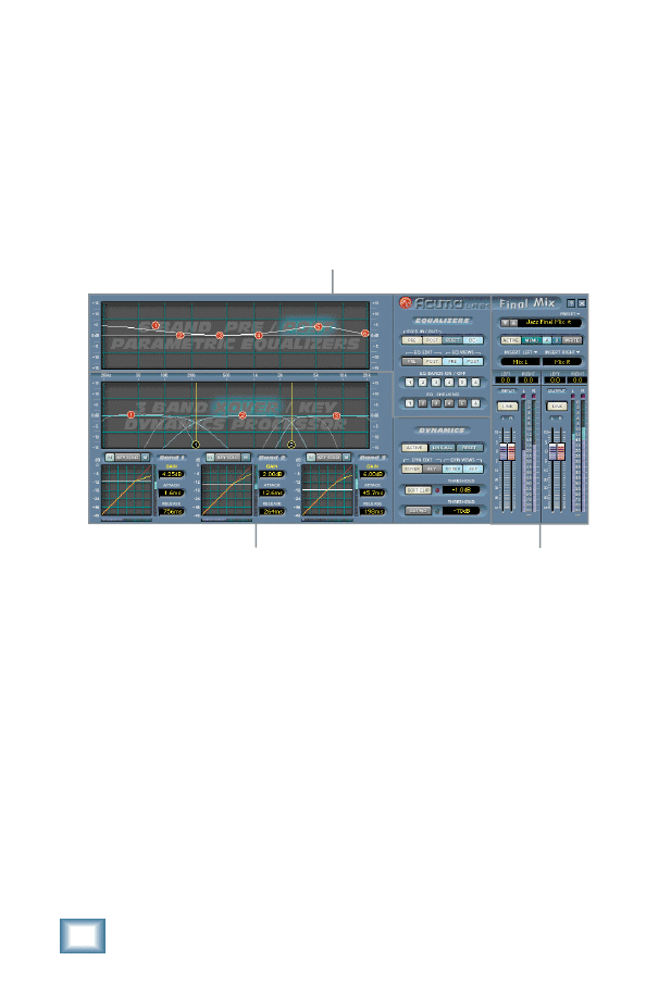
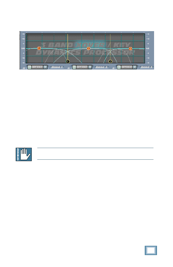
Dynamics - Crossovers/Keying Graph
Crossover and Key graph
Overview of Operation
This graph is used to set up these two interrelated functions. As
with Pre and Post EQ, parameters and views of this screen are
controlled using four buttons to the right of the graph. These
are: DYN EDIT XOVER and KEY, and DYN VIEW XOVER and
KEY. DYN VIEW enables or disables viewing. DYN EDIT selects
which feature is being edited. To facilitate viewing this
information, the function which is not being edited is dimmed.
The purpose of the crossover is to split your incoming signal into
three different bands (Low, Mid, and High). Each of these bands
feeds into its own dynamics processor.
Note: You can see a block diagram of the processing path by clicking on the
question mark (?) on the top right corner of the Final Mix main screen.
Typically, the dynamics processor is used as a compressor.
However, depending on the settings it can act as a compressor,
limiter, or expander, or even a combination of all three. Having
three dynamic processors acting separately on each band is a
large sonic improvement over a single compressor. For instance,
you don’t have to worry about your bass causing your lead vocal
to get compressed. All bands can be compressed individually,
resulting in a tighter, punchier overall sound.
Each crossover band has its own key filter. This can be used to
emphasize or de-emphasize the key (or control) signal within a
band.
14
Acuma Final Mix
The crossover points are represented by the black balls with
vertical yellow lines. These can be adjusted by dragging and
dropping the two black nodes (balls), found at the bottom of the
screen. The slope of the crossovers determines how sharply the
adjacent bands are separated. The slope can be adjusted by
right-clicking on these crossover balls and moving the mouse.
Below the graph, there are three sets of three buttons labeled
IN, KEY SOLO, and M (for mute). These are very handy for
helping you to set up your crossover and key filters. Mute will
mute the crossover band. By muting all but one band at a time,
you can listen to exactly what part of your mix is going into each
band. Similarly, KEY SOLO acts as an override, allowing you to
listen to just the key signal. The IN button switches dynamics
processing on and off for the band. This allows you to hear
exactly what is going on in each band.
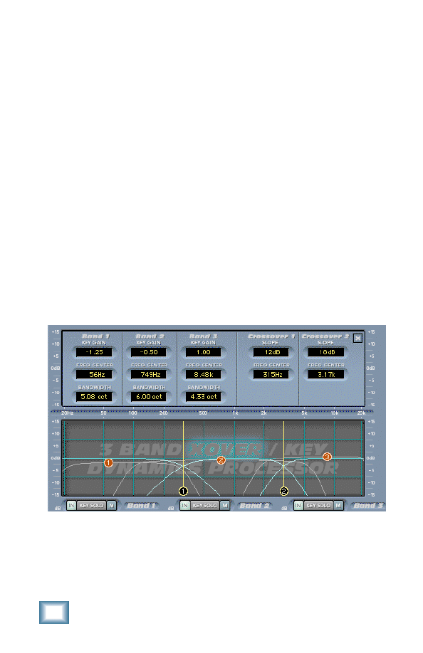
Control Panel
Double-clicking on the graph brings up a screen which displays
all of the parameters for the crossover and key filters.
Crossover/Key Values panel
All the values from this screen can be adjusted by clicking on
the digits and spinning them up or down with your mouse. You
can also use the up and down arrows on your keyboard to nudge
the parameter a small amount.

User’s Guide
15
Key Gain
The Key Gain Control ranges from –15 dB to +15 dB. This gain
control is not the same as the compressor make-up gain, which
is found in the contour screen (and beside the three small
contour graphs). Instead, this control adjusts the gain of the key
signal that is sent to the compressor. You can use this, for
instance, to drive the control signal to the compressor a little
harder. This results in the signal becoming more compressed. It
is also useful if you notice that the compressor input signal is
very low, and you want to boost it up to a more moderate level.
The compressor input signal is indicated by the horizontal meter
below the contour graph.
Frequency Center/Bandwidth
Each key has its own adjustable frequency center and bandwidth
controls. These controls can be used together to zero in on a
specific portion of the signal. Bandwidth, the inverse of Q, is
measured in octaves and ranges from 0.0 to 10.0 octaves. You
can use the KEY SOLO button, located directly below the
Crossover/Key graph, to listen to the key signal.
These controls give you further choices concerning what the
compressor does with the band. For instance, let’s say you’ve set
up the low band (Band 1) of your compressor so it contains
mostly the bass and kick drum. If you want to compress more of
the bass than the kick drum, you can use the low band’s key
filter to hone in on the bass. Then more of the bass is sent to the
compressor key than the drum. The result is that the bass tends
to compress more than the drums.
16
Acuma Final Mix
Dynamics Processing
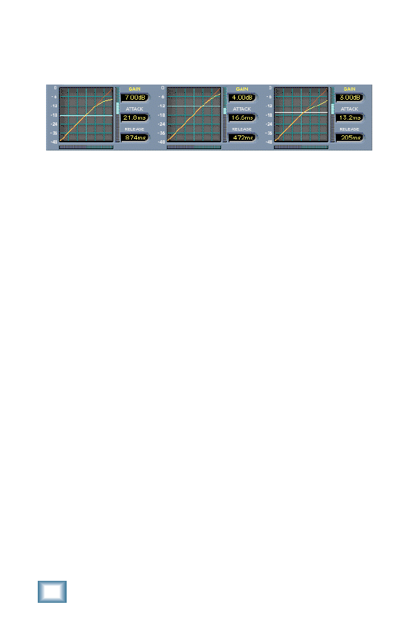
Dynamics overview
Overview
Final Mix’s crossover splits the signal into three bands, each of
which is fed into its own independent dynamics processor.
Typically, the dynamics processor is used as a compressor.
However, depending on the settings it can act as a compressor,
limiter, or expander, or even a combination of all three.
The three windows at the bottom of the screen offer an overview
of the dynamics settings for each of Final Mix’s three bands. The
graph shows the dynamics contour. It is a graph showing the
band input level (on the horizontal) vs. what the output level will
be (on the vertical) after passing through the dynamics
processor. The white horizontal line is the threshold. Below this
value, the signal is unaffected. Beside the graph are readouts
and controls for the band make-up gain, attack time, and release
time.
Double-clicking on any of the smaller contour screens brings up
a larger editing screen for detailed editing. Once the larger
screen has been accessed, contour values for a selected band are
edited by dragging and dropping nodes.
User’s Guide
17
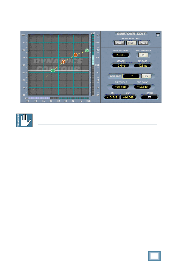
Contour Edit Screen
Contour Edit screen
Note: The Dynamics Contour Edit screen is accessed by double-clicking on any
of the three bands found at the bottom of the main Final Mix screen.
Overview
The Contour Edit Screen allows you to have very powerful
control over the heart of Final Mix. Double-clicking on any of the
three dynamics overview screens brings up this more detailed
screen. The overview screens are found at the bottom of the
main screen. The graph you see when first accessing this screen
represents the dynamics contour for the currently selected band.
This graph shows the band input level (on the horizontal) vs.
what the output level will be (on the vertical) after passing
through the dynamics processor.
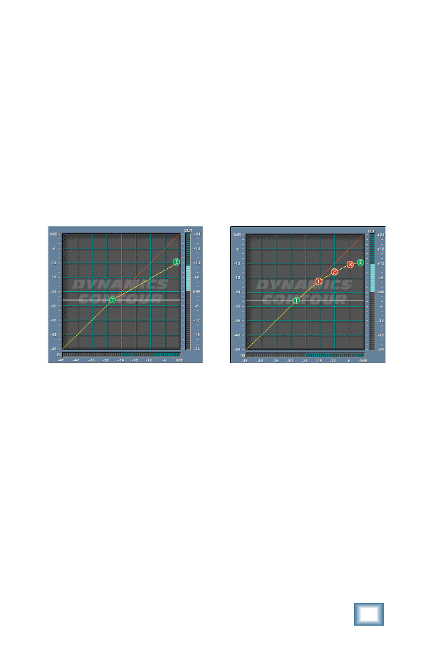
The threshold is shown as the white line with the “T” node
attached. The graph also shows the contour’s moveable end
point (designated by the green node, labeled “E”). The end point
represents a selected band’s maximum output level. The
traditional Compression Ratio is affected by both of these
parameters. One of the very powerful features of Final Mix is
that you can set up your contour to have different compression
ratios for different input levels. This is achieved by using
multiple nodes. The figure above shows 2 extra nodes – the red
balls labeled 1 and 2. These nodes are being used, in this case,
18
Acuma Final Mix
to essentially draw a knee for the compressor curve. This gives a
nice smooth transition from applying minimal compression at
low input levels, to much higher compression at higher levels.
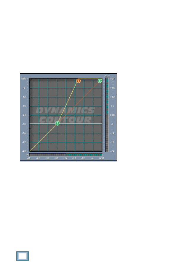
The red line that crosses the graph diagonally represents unity
gain (i.e., the signal is unaffected by the dynamics processor).
Contours which are steeper than this, as illustrated below by the
segment between T and 1, represent expansion.
Expansion section
Expansion can be used to bring a little bit more dynamics or
‘life’ into a performance. Note that each individual segment can
be set as either a compressor or an expander. Having expansion
for low input signals and compression for higher signals is a
good way to level out a signal's dynamics. Quiet signals become
louder and louder signals become quieter. We see an example of
this on the next page. For input signals below node 2 in
amplitude (approximately –28 dB), the dynamics processor acts
as an expander. For signals above node 2, the processor is a
compressor. See the section marked ‘Node editing’ on page 21 to
find out more about how to set up these kinds of contours.
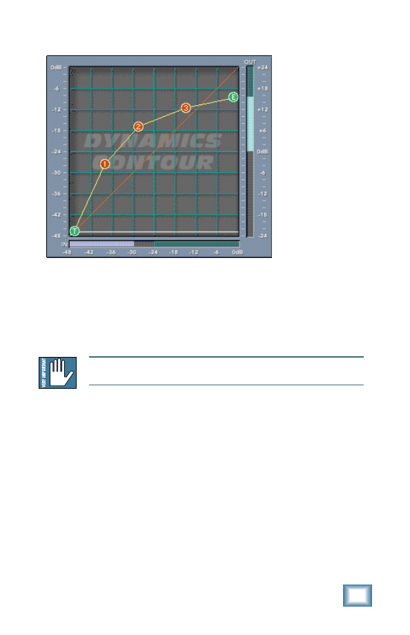
User’s Guide
19
Expansion and compression together to “level” a signal
Band View/ Edit
One dynamics band can be edited at a time from the contour
screen. However, individual bands can be quickly accessed by
choosing a band from the BAND VIEW/EDIT radio buttons found
at the top of the contour edit section.
Note: If you press the ‘LINK ALL’ button, located just to the right of the
dynamics graph, all three bands are affected at once.
Gain Makeup and Auto Makeup
Gain Makeup is used to make up for volume that has been
decreased due to compression. The Gain Makeup window ranges
from –15 dB to +15 dB and can be adjusted with a mouse to
scroll the values up or down. This control can also be accessed
from the window labeled as GAIN found in the Dynamics
overview. You can also apply attenuation using this control. This
is represented by a negative value (i.e., –3.0 dB).
When the AUTO MAKEUP button is in, Final Mix automatically
chooses an appropriate makeup gain for you. This makeup gain
is based on your dynamics contour. You can still use the ‘manual’
gain makeup control in this case. It merely adds to the makeup

20
Acuma Final Mix
gain automatically applied. When you first push the AUTO
MAKEUP button in, Final Mix adjusts your makeup gain
parameter so that the volume does not suddenly jump up. This is
hearing (and speaker) protection!
Attack and Release
The attack parameter specifies how quickly gain reduction (or
expansion) occurs at the attack, or beginning, of a signal.
Release controls how quickly gain reduction backs off when the
signal drops back down. The time is measured in milliseconds
and corresponds to the length of time it takes to achieve a fixed
amount of compression.
In general, the attack time should be much faster than the
release time to get pleasing results. If the attack time is set too
quickly, you hear something resembling clipping on attacks.
Leaving the attack a little bit longer also allows more of the
‘snap’ of the attacks to pass through the compressor. Setting a
release time too fast can result in ‘buzzing’, especially on low
notes. This occurs because the compressor gain is actually
following individual cycles of the incoming waveform.
If you set the attack time to 0 ms, the dynamics section actually
behaves as a limiter. It won't permit the signal to go over the
end point value.
As a general rule of thumb, lower frequencies require longer
release times than higher frequencies. If a high- or
mid-frequency band has a release time that is too long, you hear
the compressor ‘breathing’.
Threshold
Threshold sets the point at which compression (or expansion)
starts to occur. Final Mix’s threshold is displayed as the white
line in the middle of the graph with the green “T” node attached.
You can adjust the threshold using your mouse to drag the line
up or down. The threshold level ranges from –48 dBfs (dB
referenced to full scale within the D8B) to 0.0 dBfs. The
Threshold can also be adjusted in the Threshold window—use
your mouse to scroll the values up or down.
User’s Guide
21
Node Editing
Final Mix’s Node Editing is a unique and powerful feature that
goes far beyond the usual concept of assigning a dynamics
band’s ratio. The Contour Edit screen allows you to draw your
own curve between the threshold and the end point. Up to four
nodes can be added to the curve. This depth of editing is helpful
in defining detailed nuances in your curve such as hard knee,
soft knee, and expansion. In the previous example we saw
expansion combined with compression to implement a leveling of
the signal. This is where the quiet sections become louder and
louder sections become quieter. Below we see hard and soft
knees drawn in.
Hard Knee curve
Soft Knee curve
Examples of Hard Knee and Soft Knee curves
About Hard Knee and Soft Knee Compression
The terms hard and soft do not refer to sound but rather the way
that the compressor reacts to incoming signal. The difference is
somewhat subtle to hear but is more apparent at higher
compression ratios. A hard knee setting is well suited to lower
ratios. When using higher compression ratios, you may find it a
little better sounding to draw in a smoother knee curve. Look at
the graphs above. A hard knee curve is represented as a straight
line that connects a point on the threshold to the end point or
maximum output on the graph. A soft knee curve has a smoother
curve that connects the two points. This creates a more gradual
transition between non-compressed and compressed signals.

22
Acuma Final Mix
Nodes can be added to the contour graph by right-clicking the
mouse on the contour graph. Right-clicking on the graph where
there is no node adds a node, up to a maximum of 4. Right-clicking
on a node removes it. You can also add or remove nodes by
scrolling through the NODE selector window and toggling the IN
button. The NODE selector window is located in the panel
immediately to the right of the contour graph in the Contour Edit
Screen. The IN button is seen just to the right of the node selector
window.
Note: The four numbered nodes must always appear in order from left to right.
A consequence of this is that you can't add a node between, for instance, nodes 1
and 2, even if they are the only 2 nodes active.
Nodes on the graph can be adjusted by the standard drag and drop
method. You can also edit the node’s In and Out levels in the small
windows at the bottom right of the contour edit screen. Beside
these two windows, you will see a RATIO display. The ratio is
automatically calculated when the node is moved and can't be
directly edited. The RATIO display corresponds to the dynamics
ratio applied in the segment immediately to the left of the selected
node.
The RATIO window displays both compression and expansion.
When a segment represents expansion, the ratio is displayed as,
for instance, 1:2.5. However, a compression ratio shows as 2.5:1.
Final Mix also implements negative compression ratios. This is
useful only for special effects. In this case a node appears lower in
the graph than the one to its immediate left. For negative
compression, the ratio window displays, for instance, –2.5:1.
Other Controls in the Dynamics Section
Active
This engages or disengages all of the compressors.
Note: The dynamics processor for each band can be individually enabled or dis-
abled using the IN button immediately below the key/crossover graph.

User’s Guide
23
Reset
RESET DYNAMICS will reset the Dynamics section to its factory
default settings.
Link All
When engaged, this button allows you to edit all three bands of
dynamics at once. Changes don't take place until you move a
parameter within the dynamics section.
Soft-Clip On and Threshold
The SOFT CLIP button activates a soft-clip limiter circuit. There
is also a THRESHOLD adjustment. These controls are located
just to the right of the three small contour screens. When the
output of the dynamics section goes above this threshold, the
soft-clip circuit kicks in. This circuit starts adding analog-style
distortion. This avoids the harsher sound of a straight digital
clip. The lower the threshold, the more analog-style distortion is
added. If the threshold is set too low, you hear this as a very
crunchy distortion sound. It is best to keep the threshold
between –3 dB and –1 dB unless you are going for a special
sound effect.
The soft-clip circuit has an indicator light, located between the
SOFT CLIP button and the THRESHOLD adjustment. This
activates when the signal is above the soft-clip threshold.
The soft-clip circuit is the last thing in the signal processing
chain. If you notice it become active and wish to avoid any kind
of distortion being added, you can merely back off the output
faders.
Noise Gate and Threshold
Final Mix also has a simple noise gate with a threshold
adjustment. These controls are located just to the right of the
three small contour screens (GATING and THRESHOLD). The
noise gate threshold can go from 0 dBfs to –125 dBfs. The
attack rate (when the gate opens) is very fast. The release rate
is very slow. This can be used as an effect to generate a very
slow, smooth fade out of a song. To do this, set the threshold at
0 dB with the noise gate disabled. When you want to start the
fade out, enable the noise gate and the fade out starts. The fade
out lasts about 5 seconds.
24
Acuma Final Mix
The noise gate is located post-dynamics but pre-output fader.
That is, adjustments made in the output fader do not affect the
performance of the noise gate.
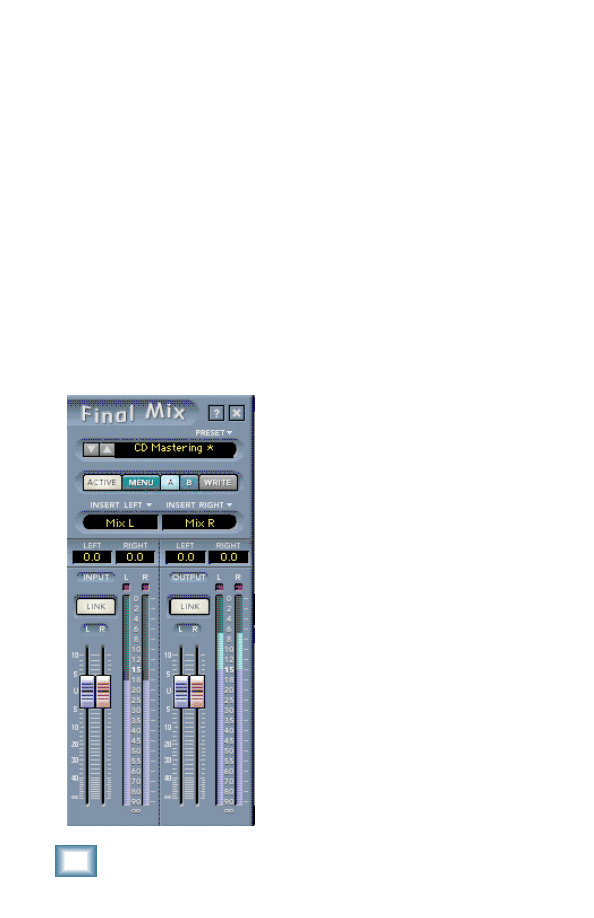
Global Controls Block
The Global Controls Block is shown below. This includes the
minimize and preset up/down buttons, the preset title window,
the ACTIVE MENU, Mem A/B, and the WRITE buttons. The
global controls also include INPUT and OUTPUT faders and
meters, and fader LINK buttons.
The INSERT LEFT/RIGHT windows allow you to insert Final
Mix into any channel within the D8B. LEFT/RIGHT numeric
readouts display values of the main left and right input and
output faders. The LINK buttons found above the input and
output faders link the left and right channels together.
Main Global Controls screen

User’s Guide
25
Help Screen (?)
Pressing the help screen (?) button brings up a handy quick
reference screen to assist you in using Final Mix. It offers a signal
path block diagram, definitions, and editing tips. Toggle the arrows
to change screens.
Minimize Button (X)
The minimize button (X) in the top-right corner hides the screen.
However, the screen is still active until it is disabled in the D8B
Plug-ins window.
Preset Toggle Buttons
The preset up/down arrow buttons enable you to scroll up or down
through either the factory or user presets. These toggle buttons
are located just to the left of the Preset window.
Preset Title Window
The Preset Title window displays the currently selected preset.
This window is located at the top of the control bar. Click on it to
access the pull-down menu where you can choose between factory
or user presets.
Memory A/Memory B
The Mem A and Mem B buttons temporarily store Final Mix
settings to allow comparative referencing. You can also copy and
paste settings from one memory location to another using
commands found on the menu.
Menu
Pressing the MENU button opens a pull-down menu that performs
familiar functions. Some of these functions are load, save as, cut,
copy, paste, and show the plug-in's build and version numbers.
Write
WRITE enables the D8B’s automation so all changes you make in
the Final Mix plug-in are recorded as part of a D8B session. This
works like a channel’s write button. To record automation for a
plug-in, automation must be out of Bypass. “ALL” must also be
turned on in the automation section of the D8B. When the D8B is
recording, plug-in parameter edits are recorded only if the plug-in's
write button is on, or if Auto Touch (in the automation section) is
turned on. When you hit stop, the plug-in’s write button turns off.

26
Acuma Final Mix
Insert Left/Right
Typically you will use Final Mix for mastering your project to
CD, DAT or hard disk. Selecting Mix L and Mix R inserts Final
Mix on your main outputs.
Tip:
You will typically use Final Mix to master your D8B
sessions. However, it also works well for equalizing and
compressing incoming stereo tracks recorded to tape or
hard disk.
L/R Input Clip LEDs
The two small boxes at the top of the input meters are the input
clip LEDs. The clips blink if the signal goes above 0 dB. Here's
what to try if the output LEDs are clipping but the inputs are
not. You can generally get rid of clipping by backing off the
output faders slightly.
Link
The LINK button links the Left and Right input faders so they
can be moved simultaneously. If the faders have an offset when
link is engaged, they maintain that offset.
Please see Appendix C of the Digital 8•Bus version 3.0 owner’s
manual for information on:
• Saving, loading and resetting a preset
• Automation and snapshot control
• Dynamic real time and dynamic off-line
• FX routing
User’s Guide
27
Specifications
6 band parametric EQ
Gain
±
15.0 dB
Frequency
20Hz to 20kHz
Q range
0.1 to 16
Filter type
High/Low shelf
or bandpass
Dynamics
Gain Makeup
±
15 dB
Attack
0 to 100 ms
Release
30ms to 3000 ms
Threshold
–48 dBfs to 0 dBfs
Compressor Contours
Four nodes per
dynamics band,
each allowing for
any possible
compression or
expansion ratio
from 1:inf to inf:1
Input/ Output Meters
–90 dBfs to 0 dBfs
Routing
Pre or post insert,
auxiliary,
master L/R.
Soft-Clip
Threshold
0.0 dB to –20.0 dB
Input/ Output Faders
+10 dB to off
Noise Gate Threshold
0 dBfs to –125 dBfs
Crossover Frequencies
20 Hz to 20kHz
Crossover slopes
6 dB/octave to 36 dB/octave
Key Filters
Frequency
Limited to
crossover band
Slope
4
th
order low pass
4
th
order high pass
DC filter
On/off, frequency = 3.3Hz

28
Acuma Final Mix
Final Mix Factory Presets
The following table is a simple guide to help you understand
some of Final Mix’s factory presets. A brief description and
intended use is given. Final Mix presets can be used effectively
as they are, or as a starting point that lets you do the fine tuning
mix. Final Mix also lets you create your own user presets with
custom parameters that meet your specific needs. So get
creative and have fun! Please visit www.acumalabs.com
periodically to download new audio examples and additional free
presets.
Note: Certain preset names shown here have the prefix ( H_). This indicates
that the preset is associated and explained in Final Mix’s help screen. The help
screen is accessed by selecting the (?) found at the top right hand corner of
the screen.
Final Mix Preset
Preset Description
Preset Type
Acuma CD Mastering A great full range compression
Any style mastering
preset for all-around mastering.
Acuma Dance Mix
Optimized dance mix guaranteed
Dance production
to keep the beat pumping.
mix
Acuma Final Mix
Finely detailed midrange.
All around mastering
Great for any style.
Acuma Gentle Comp
Soft and gentle compression levels Easy mix
for a light but definitive mix.
Acuma Punch
Medium compression emphasizing
Funky, punchy mix
low and high end compression.
Acuma Rock + EQ
Great all-around rock compression
Rock and roll mix
with a boost in the low, mid and
hi EQ.
Acuma Techno
EQ with the perfect fat bottom mix Techno, trance,
and a sizzling, crisp top end.
house, groove mix
Perfect for techo, house and
groove.
Acuma The Leveler
Maximizes your output level with a Hot output mix
very warm analog sound.
Country + EQ
Just the right compression and EQ
Country mix
creates a lively modern country mix.
Country Female
Especially designed for today’s top
Female- country mix
country music female singing sound.
Country Mix
All around country music with just Male country mix
right crossovers and compression.
Drums
The ultimate drum compression.
Drum mix (any style)
Good for all styles of drumming.

User’s Guide
29
Drums with Exp
Add some snap and punch to drum
Drum mix (any style)
tracks with a mix of expansion and
compression.
Female Broadcast
Optimized Female compression
Radio and television
settings for radio or TV broadcast.
broadcast (female)
Uses an EQ lift between 100 and
300Hz with a 75Hz roll off. This
simulates Electro Voice RE-20
microphone response.
Female Vox Comp
Good all around compression
Good over all female
and EQ. Good for most female
vocal mix
singing voices.
Final Mix Vocal
Medium compression set to
Use with any vocal
optimal vocal crossover points
style
500Hz to 2.5K.
General CD Mastering General purpose, all around
General all around
mastering.
mastering
H_+6 dB Gain
A 6 dB lift created by a +3 dB input +6 dB boost
gain and a +3 dB output gain.
Linked contour bands are set to
1:1 so they don’t introduce any
compression.
H_12 Band EQ
Shows off overlapping the 6 bands
Demonstrates how
of pre and post EQ’s to form a
the pre and post EQs
12-band parametric EQ.
can be combined to
create a 12-band EQ
H_Bass
Pre EQ, high shelf; post EQ, low
Compress bass,
Comp-Treble Exp
shelf. The contours are set to add
expand treble
compression to the lows, and
expansion to the highs.
H_Jazz Mix
Uses 3-band pre EQ w/three bands
Contemporary jazz
of compression that are set as
mastering
tighter bass, mids, and highs.
H_Leveler With EQ
Three bands of pre EQ with a shelf Hot output + EQ mix
set on the highs. A pronounced
key in the lows, and 6 dB of gain
makeup. Comp bands are linked.
H_Loudness &
Mild loudness EQ curve set by
Hot output with
Mild Comp
post EQ peak in the lows, and a
mid boost
shelf in the highs. Linked comp
bands with medium attack and
slow release used for over-all
compression.
H_Loudness EQ
Smiley-face EQ to compensate for
Hot output + EQ mix
quiet levels.
H_Mid Lift
Simple wide Pre EQ midrange lift.
Boosts midrange
compression

30
Acuma Final Mix
H_Mild Expansion
Three contour bands are set to act
Expands midrange
as midrange expanders to add a bit
more dynamics and liven up
a performance.
H_Notch EQ
One pre EQ band set extremely low. Use to eliminate bad
Used to remove a
frequencies
problem frequency.
H_One Comp Band
Uses the middle contour band as a
Used as one over all
single broadband compressor. The
compressor
Xover has its borders at 20Hz and
20kHz with 36 dB slopes. The band
two key is set to match the Xover.
H_Punchy Kick
Knock you through the wall kick
Rock steady bass
sound. Soft low band compression
drum mix
with 100Hz pre EQ lift.
H_Smooth Highs
Heavy high end compression with a Emphasize high end
Post EQ high shelf lift.
H_Telephone Comp
Special effect that simulates
Telephone effect
telephone reception. Shows off the
concept of shutting bands off as
effects.
H_The Leveler #2
Linked comp bands @ 1.79:1 ratios. Good overall master
A small post EQ high lift is added.
output control
Use the Thresh or Input Gain faders
to add or remove compression.
The Output faders are used to trim
over all.
Heavy Vox +
Heavily compressed vocal setting
Heavy vocal
10K Boost
and 10k boost with linking bands.
compression with
10k lift
Instrumental
Perfectly tweaked compression for All-around
any instrumental mix.
instrumental mix
Jazz Final Mix
The perfect mastering compliment
All-around jazz mix
to well recorded live jazz.
Light + EQ
Just a touch of compression with
Easy comp
EQ for subtle mastering.
mastering +EQ
Light Vox Comp + EQ Just a touch of light compression
Light vocal
with optimized vocal cross overs.
compression with EQ
Long Distance
Hello out there, does anyone
Far away effect
hear me? Spacey EQ and
compression effect.
Loudness
Gives you hotter output.
Hot output
mastering
Male Broadcast
Optimized Male compression
Radio and television
settings for radio or TV broadcast.
broadcast (male)
Uses an EQ lift between 100 and
300Hz. Has a 75Hz roll off to
simulate Electro Voice RE-20
microphone response.

User’s Guide
31
Male Vox Comp
Good all around compression and
Good over all male
EQ. Good for most male singing
vocal mix
voices.
Moderate + Hi Low EQ Moderate compression with high
High and low EQ
and low EQ boost.
boost
Moderate + Mid EQ
Moderate compression with a bit of Mid EQ boost
EQ boost for mid frequencies.
Orchestral
Finely tuned light compression for
All-around
full orchestra.
orchestra mix
Pop
Medium, non-intrusive compression. All-around pop mix
Pump DA Bass
Pumps up the low end for an ultra
Fat bottom end
phatt sound.
Punch
Medium compression emphasizing
Punchy R&B mix
low and high end compression.
Radio Punch Mix
Gives your mix added punch for
Add punch for radio
radio or television. Designed for
and television
FM frequencies.
Sell It!
In your face sound that can’t
Up front and
be denied.
noticeable
Smoothed Out 1
Top and bottom compression just
Lifts and tightens a
offset from key centers.
lifeless mix, mild
compression boosts
bottom and top end
Smoothed Out 2
Variation of Smoothed out 1.
Smoothed Out 3
Variation of Smoothed out 1.
Squash It 1
Extreme compression.
Heavy compression
Reminiscent of the main mix
compressor on an SSL when it’s
pushed hard into a Pultec EQ.
Squash It 2
Variation (extreme compression).
Heavy compression
Reminiscent of the main mix
compressor on an SSL when it’s
pushed hard into a Pultec EQ.
Squawk Squash
Designed to crush heavy midrange
Mid killer
(2-5k).
The Brass Balls
Medium to heavy compression with In your face, to the
bass boost EQ.
wall compression
with bass boost
Vocal
General purpose vocal mastering;
Good on vocals
less compression in the middle to
preserve a singer’s dynamics.

©
2001 Mackie Designs Inc. and Acuma Labs. All Rights Reserved.
Part No. 0000815 Rev. 5 12/2001
™
®
Document Outline
- Contents
- Iconography
- Introduction
- About Acuma Labs (www.acumalabs.com)
- About the D8B UFX Card
- About Final Mix
- Main Features
- Let’s Get Started
- Requirements
- Using Final Mix
- Front Panel Overview
- Pre/Post Equalizers (Six-band)
- Dynamics - Crossovers/Keying Graph
- Dynamics Processing
- Contour Edit Screen
- Node Editing
- Other Controls in the Dynamics Section
- Global Controls Block
- Specifications
- Final Mix Factory Presets
Wyszukiwarka
Podobne podstrony:
OM z 04 2013 05 02 ko
Pisownia ę ą en em om
oversigt over krav om radioudstyr revision 10 5 2001
OM 602
OM cw1
3b Zasoby OM w ukladzie katenalnym folia
340069 CS300 RevA 05 5 PL
Polecenia OM poprawione
23 Fortell om situasjonen? oljen truet hele sørøstkysten av USA
TEATR OPRACOWANIA I sem, balme teatr w +Ťwiecie widowisk, rozdz II om+-wienie
23(3), Wpadli do sadu, chy˙kiem przesun˙li si˙ pod obwis˙ymi ga˙˙ziami i pr˙dko, trwo˙nie, niby sp˙o
odpowiedzialność wszystkich wobec spółki kapitałowej (6 str), Om?w odpowiedzialnosc czlonk?w, organ?
Opracowanie pytan MC KULA MC OM Nieznany
OM 16 10 10
62 67 ortografki ą, ę, en, em, on, om
OM KRC 901 1995 KUSA
Cele i organizacja działalności Banku Światowego, SGH, OM
więcej podobnych podstron