
General Information
UNITED STATES COAST PILOT
(1)
The United States Coast Pilot, published by the Na-
tional Oceanic and Atmospheric Administration
(NOAA), is a series of nine nautical books (volumes)
that encompasses a wide variety of information impor-
tant to navigators of U.S. coastal/intracoastal waters
and the waters of the Great Lakes. The Coast Pilot is in-
tended to be used as a supplement to NOAA nautical
charts. Much of the content cannot be shown graphi-
cally on the charts and is not readily available else-
where.
Topics
which
are
covered
include
environmental factors of weather, climate, ice condi-
tions, tides, water levels, currents, prominent coastal
features and landmarks. Specific information on verti-
cal clearances, wharf descriptions, small-craft facili-
ties, hazards, dredged channels and depths are also
provided. Navigation services and regulations are also
identified including pilotage, towing, anchorages,
routes and traffic separation schemes, environmental
protection, and other Federal laws.
(2)
Amendments to this publication are available at:
(3)
http://nauticalcharts.noaa.gov/nsd/cpdownload.htm.
(4)
U.S. Coast Guard (USCG) Local Notices to Mariners
(5)
http://www.navcen.uscg.gov/lnm/default.htm.
(6)
National Geospatial-Intelligence Agency (NGA)
U.S. Notice to Mariners
(7)
http://www.nga.mil/portal/site/maritime/.
Using the Coast Pilot
(8)
Chapter 1 contains definitions of general and stan-
dard terms used throughout the volume; discussion of
NOAA charting products and services; descriptions of
maritime services by various U.S. Government agen-
cies; Notices to Mariners, and other information perti-
nent to safe navigation.
(9)
Chapter 2 contains selected extracts from the Code
of Federal Regulations (CFR) that affect mariners.
(10)
Chapter 3 contains general information that is pe-
culiar to the region covered by a particular Coast Pilot
volume. For example, practical information regarding
offshore currents and dangers, coastal aids to naviga-
tion, prominent landmarks, and the general character
of the coast and depths helpful in approaching the re-
gion.
(11)
In Chapter 4 and the remaining numbered chap-
ters, the detailed description of the region begins. A
map precedes each chapter and outlines the nautical
charts used in the area to be discussed. In these chap-
ters, as much as possible, the coastal description is in
geographic sequence, north to south on the east coast,
east to west on the gulf coast, clockwise around each of
the Great Lakes, and south to north on the west coast
and Alaskan coast. Features are described as they ap-
pear on the largest scale chart, with that chart number
prominently shown in blue.
(12)
Appendix A contains contact information regard-
ing the various products, services, and agencies de-
tailed throughout the volume.
(13)
Appendix B contains useful reference tables re-
garding, climate, meteorology, unit of measure conver-
sions, abbreviations, etc.
(14)
The Index contains geographic names mentioned
throughout a Coast Pilot volume. These names are
boldfaced and indexed along with the number of the
largest scale chart on which the entire feature appears.
Bearings
(15)
These are true, and expressed in degrees from 000°
(north) to 359°, measured clockwise. General bearings
are expressed by initial letters of the points of the com-
pass (e.g., N, NNE, NE, etc.). Whenever precise bear-
ings are intended, degrees are used. Light-sector
bearings are toward the light.
Bridges and cables
(16)
Vertical clearances of bridges and overhead cables
are in feet above mean high water unless otherwise
stated; clearances of drawbridges are for the closed po-
sition, although the open clearances are also given for
vertical-lift bridges. Whenever a bridge span over a
channel does not open fully to an unlimited clearance
position, a minimum clearance for the sections over
the channel should be given; the same guidelines apply
to swing and pontoon bridges with openings less than
50 feet horizontally. Clearances given in the Coast Pilot
are those approved for nautical charting, and are sup-
plied by the U.S. Coast Guard (bridges) and U.S. Army
Corps of Engineers (cables); they may be as-built (veri-
fied by actual inspection after completion of struc-
tures) or authorized (design values specified in the
General Information
■
Chapter 1
■
1

permit issued prior to construction). No differentiation
is made in the Coast Pilot between as-built and autho-
rized clearances. (See charts for horizontal clearances
of bridges, as these are given in the Coast Pilot only
when they are less than 50 feet (15 meters). Although,
there are exceptions in two Coast Pilot books; they are
Coast Pilot 6 and 7, in areas where tables are used all
horizontal clearances are listed.) Submarine cables are
rarely mentioned.
Cable ferries
(17)
Cable ferries are guided by cables fastened to shore
and sometimes propelled by a cable rig attached to the
shore. Generally, the cables are suspended during
crossings and dropped to the bottom when the ferries
dock. Where specific operating procedures are known
they are mentioned in the text. Since operating proce-
dures vary, mariners are advised to exercise extreme
caution and seek local knowledge. DO NOT ATTEMPT
TO PASS A MOVING CABLE FERRY.
Currents
(18)
Stated current velocities are the averages at
strength. Velocities are in knots, which are nautical
miles per hour. Directions are the true directions to
which the currents set (see Chapter 3, this book).
Depths
(19)
Depth is the vertical distance from the chart datum
to the bottom and is expressed in the same units (feet,
meters or fathoms) as those soundings found on the
chart. (See Chart Datum, this chapter, for further de-
tail.) The controlling depth is the least known depth of
a channel. This depth is determined by periodic hydro-
graphic surveys, and restricts use of the channel to
drafts less than that depth. The centerline controlling
depth applies only to the channel centerline or close
proximity; lesser depths may exist in the remainder of
the channel. The midchannel controlling depth is the
controlling depth of only the middle half of the chan-
nel. Federal project depth is the original design dredg-
ing depth of a channel planned by the U.S. Army Corps
of Engineers and may be deeper than current condi-
tions. For this reason, project depth must not be con-
fused with controlling depth. Depths alongside
wharves usually have been reported by owners and/or
operators of the waterfront facilities, and have not been
verified by Government surveys. Since these depths
may be subject to change, local authorities should be
consulted for the latest controlling depths.
(20)
For all maintained channels with controlling
depths detailed on charts in tabular form, the Coast Pi-
lot usually states only the project depths. For all other
channels which may be depicted on charts with depth
legends, notes or soundings, the Coast Pilot will strive
to list the corresponding controlling depths with the
dates of the latest known surveys. Depths may vary
considerably between maintenance dredging; consult
the Notices to Mariners for latest controlling depths.
Under-keel clearances
(21)
It is becoming increasingly evident that economic
pressures are causing mariners to navigate through
waters of barely adequate depth, with under-keel clear-
ances being finely assessed from the charted depths,
predicted tide levels, and depths recorded by echo
sounders.
(22)
It cannot be too strongly emphasized that even
charts based on modern surveys may not show all
sea-bed obstructions or the shoalest depths, and actual
tide levels may be appreciably lower than those pre-
dicted.
(23)
In many ships an appreciable correction must be
applied to shoal soundings recorded by echo sounders
due to the horizontal distance between the transduc-
ers. This separation correction, which is the amount by
which recorded depths therefore exceed true depths,
increases with decreasing depths to a maximum equal
to half the distance apart of the transducers; at this
maximum the transducers are aground. Ships whose
transducers are more than 6 feet (1.8 meters) apart
should construct a table of true and recorded depths
using the Traverse Tables. (Refer to the topic on echo
soundings elsewhere in chapter 1.)
(24)
Other appreciable corrections, which must be ap-
plied to many ships, are for settlement and squat. These
corrections depend on the depth of water below the
keel, the hull form and speed of the ship.
(25)
Settlement causes the water level around the ship
to be lower than would otherwise be the case. It will al-
ways cause echo soundings to be less than they would
otherwise be. Settlement is appreciable when the depth
is less than seven times the draft of the ship, and in-
creases as the depth decreases and the speed increases.
(26)
Squat denotes a change in trim of a ship underway,
relative to her trim when stopped. It usually causes the
stern of a vessel to sit deeper in the water. However, it is
reported that in the case of mammoth ships squat
causes the bow to sit deeper. Depending on the location
of the echo sounding transducers, this may cause the
recorded depth to be greater or less than it ought to be.
Caution and common sense are continuing require-
ments for safe navigation.
Distances
(27)
These are in nautical miles unless otherwise stated.
A nautical mile is one minute of latitude, or approxi-
mately 2,000 yards, and is about 1.15 statute miles.
2
■ Chapter 1
■
Volume 5

Heights
(28)
These are in feet (meters) above the tidal datum
used for that purpose on the charts, usually mean high
water. However, the heights of the decks of piers and
wharves are given in feet (meters) above the chart da-
tum for depths.
Light and fog signal characteristics
(29)
These are not described in the Coast Pilot. Also,
light sectors and visible ranges are generally not fully
described. This information can be found in U.S. Coast
Guard Light Lists.
Obstructions
(30)
Wrecks and other obstructions are mentioned only
if they are relatively permanent and in or near normal
traffic routes.
Radio aids to navigation
(31)
These are seldom described. (See United States
Coast Guard Light Lists, and National Geospatial-Intel-
ligence Agency Radio Navigational Aids.)
Ranges
(32)
These are not fully described. “A 339° Range”
means that the rear structure bears 339° from the
front structure. (See United States Coast Guard Light
Lists.)
Reported information
(33)
Information received by NOAA from various
sources concerning depths, dangers, currents, facili-
ties, and other topics, which has not been verified by
Government surveys or inspections, is often included
in the Coast Pilot; such unverified information is qual-
ified as “reported,” and should be regarded with cau-
tion.
Tides
(34)
Tidal information for select locations may be found
at the end of each chapter. Real-time water levels, tide
predictions, and tidal current predictions are available
at http://tidesandcurrents.noaa.gov.
Time
(35)
Unless otherwise stated, all times are given in local
standard time in the 24-hour system. (Noon is 1200,
2:00 p.m. is 1400, and midnight is 0000.)
Winds
(36)
Directions are the true directions from which the
winds blow, however, sometimes (rarely) compass
points are used. Unless otherwise indicated, speeds are
given in knots, which are nautical miles per hour.
NAUTICAL CHARTS
Chart symbols and abbreviations
(37)
NOAA’s Nautical Charts are a graphic portrayal of
the marine environment showing the nature and form
of the coast, the general configuration of the sea bot-
tom, including water depths, locations of dangers to
navigation, locations and characteristics of man-made
aids to navigation, and other features useful to the mar-
iner.
(38)
The standard symbols and abbreviations approved
for use on all regular nautical charts are in Chart No. 1,
United States of America Nautical Chart Symbols and
Abbreviations. This reference, jointly maintained by
the National Geospatial-Intelligence Agency and
NOAA, is available at http://nauticalcharts.noaa.gov/
mcd/chartno1.htm.
(39)
On certain foreign charts reproduced by the United
States, and on foreign charts generally, the symbols
and abbreviations used may differ from U.S. approved
standards. It is therefore recommended that navigators
who acquire and use foreign charts and reproductions
procure the symbol sheet or Chart No. 1 produced by
the same foreign agency.
(40)
Mariners are warned that the buoyage systems,
shapes, and colors used by other countries often have a
different significance than the U.S. system.
Chart Projections
(41)
The Mercator projection used on most nautical
charts has straight-line meridians and parallels that in-
tersect at right angles. On any particular chart the dis-
tances between meridians are equal throughout, but
distances between parallels increase progressively
from the Equator toward the poles, so that a straight
line between any two points is a rhumb line. This
unique property of the Mercator projection is one of
the main reasons why it is preferred by the mariner.
Chart Datum
(42)
Chart Datum is the particular tidal level to which
soundings and depth curves on a nautical chart or
bathymetric map are referred. The tidal datum of Mean
Lower Low Water is used on all NOAA charts, except for
charts in the Great Lakes and non-tidal inland water-
ways.
(43)
Mean Lower Low Water is defined as the arithmetic
mean of the lower low water height of each tidal day
(24.84 hours) observed over the National Tidal Datum
Epoch. The National Tidal Datum Epoch is the specific
19-year period adopted by NOAA, as the official time
segment over which tide observations are taken and re-
duced to obtain mean values for tidal datums. The
General Information
■
Chapter 1
■
3

present
Epoch
is
1983
through
2001.
See
http://www.co-ops.nos.noaa.gov/datum_options.html.
Horizontal Datum
(44)
Nautical charts are constructed based on one of a
number of horizontal datums which are adopted to best
represent individual regions around the world. Note
that the terms horizontal datum, horizontal geodetic
datum, and horizontal control datum are synonymous.
(45)
The exact placement of lines of latitude and longi-
tude on a nautical chart is dependent on the referenced
horizontal datum. Charts of the United States are cur-
rently referenced primarily to the North American Da-
tum of 1983 (NAD 83), and the World Geodetic System
1984 (WGS 84). WGS 84 is equivalent to the NAD 83 for
charting purposes.
(46)
NAD 83 and WGS 84 have replaced the North
American Datum of 1927 and other regional datums as
the primary horizontal datum to which NOAA charts
are referenced. Since many geographic positions are
still referenced to the older datums, NOAA has included
notes on charts which show the amount to shift those
positions in latitude and longitude to fit the chart’s
NAD 83 or WGS 84 projection.
(47)
It should be noted that the physical shift between
positions on older datums and NAD 83/WGS 84 was sig-
nificant. The mariner should always be certain the po-
sitions they are plotting on a nautical chart are on the
same datum as the chart.
Accuracy of a nautical chart
(48)
The value of a nautical chart depends upon the ac-
curacy of the surveys on which it is based. The chart re-
flects what was found by field surveys and what has
been reported to NOAA. The chart represents general
conditions at the time of surveys or reports and does
not necessarily portray present conditions. Significant
changes may have taken place since the date of the last
survey or report.
(49)
Each sounding represents an actual measure of
depth and location at the time the survey was made,
and each bottom characteristic represents a sampling
of the surface layer of the sea bottom at the time of the
sampling. Areas where sand and mud prevail, especially
the entrances and approaches to bays and rivers ex-
posed to strong tidal current and heavy seas, are sub-
ject to continual change.
(50)
In coral regions and where rocks and boulders
abound, it is always possible that surveys may have
failed to find every obstruction. Thus, when navigating
such waters, customary routes and channels should be
followed, and areas avoided where irregular and sudden
changes in depth indicate conditions associated with
pinnacle rocks, coral heads, or boulders.
(51)
Information charted as “reported” should be
treated with caution when navigating the area, because
the actual conditions have not been verified by govern-
ment surveys.
Source diagrams
(52)
A source diagram is provided on all NOAA charts,
1:500,000 scale and larger. This diagram is intended to
provide the mariner with additional information about
the density and adequacy of the sounding data depicted
on the chart. The adequacy with which sounding data
depicts the configuration of the bottom depends on the
following factors:
(53)
•Survey technology employed (sounding and navi-
gation equipment).
(54)
•Survey specifications in effect (prescribed survey
line spacing and sounding interval).
(55)
•Type of bottom (e.g., rocky with existence of sub-
merged pinnacles, flat sandy, coastal deposits subject
to frequent episodes of deposition and erosion).
(56)
Depth information on nautical charts is based on
soundings from the latest available hydrographic sur-
vey, which in many cases may be quite old. The age of
hydrographic surveys supporting nautical charts var-
ies. Nearly half of all inshore hydrography was acquired
by leadline (pre-1940) sounding technology.
(57)
Prior to 1940, the majority of survey data acquired
consisted of leadline soundings which were positioned
using horizontal sextant angles. This positioning method
is considered to be accurate for near shore surveys. A
deficiency with pre-1940 data exists in the leadline
sounding method because it represents discrete sin-
gle-point sampling. Depths of areas between or outside
of leadline sounding points can only be inferred or esti-
mated leaving the possibility of undetected features, es-
pecially in areas of irregular relief.
(58)
From 1940 to 1990, the majority of survey data
consisted of soundings resulting in partial bottom cov-
erage. This type of sounding data is typically acquired
using continuous-recording single-beam echo sound-
ers as stand-alone survey systems. This survey method
originally yielded a graphic record of the entire sound-
ing line from which soundings were recorded at regu-
lar intervals. Using this graphic record, features which
fell between the recorded soundings could be inserted
into the data set. Since approximately 2001, single
beam echo sounder data has been recorded digitally to
automatically include all soundings in the data set. Al-
though the sampling is continuous along the track of
the sounding vessel, features such as discreet objects or
small area shoals between sounding lines may not have
been detected. Positioning of the sounding vessel in
this period has progressed from horizontal sextant an-
gles, through land-based electronic positioning systems,
4
■ Chapter 1
■
Volume 5
General Information
■
Chapter 1
■
5
• The transit ends in an area charted from
miscellaneous surveys. These surveys may be too
numerous to depict or may vary in age, reliability,
origin or technology used. No inferences about the
fi tness of the data can be made in this area from
the diagram.
Referring again to the accompanying sample
Source Diagram, and the previous discussion of
survey methods over time, a mariner could choose
to transit from Point X to Point Y, along the track
shown with a dashed line.
• The transit starts again in an area surveyed by
NOAA within the 1900-1939 time period. The
sounding data would have been collected by lead-
line. Depths between sounding points can only be
inferred, and undetected features might still exist
between the sounding points in areas of irregular
relief. Caution should be exercised.
• The transit then crosses an area surveyed by
NOAA within the 1990 - present time period, with
partial bottom coverage. The data is collected in
metric units and acquired by continuous record-
ing single beam echo sounder. It is possible that
features could have been missed between the
sounding lines, although echo sounders record all
depths along a sounding line with varying beam
widths.
• The transit then crosses into an area surveyed by
NOAA within the 1990 - present time period, hav-
ing full bottom coverage. This area of the charted
diagram is shaded with a blue screen to draw
attention to the fact that full bottom coverage has
been achieved. The data would have been collected
in metric units and acquired by side scan sonar or
multibeam sonar technology. Undetected features
in this area, at the time of the survey, would be
unlikely.
• The transit ends in an area charted from
miscellaneous surveys. These surveys may be too
numerous to depict or may vary in age, reliability,
origin or technology used. No inferences about the
fi tness of the data can be made in this area from
the diagram.
By choosing to transit along the track shown by
the dashed line, the mariner would elect to take
advantage of more recent survey information col-
lected with more modern technology.
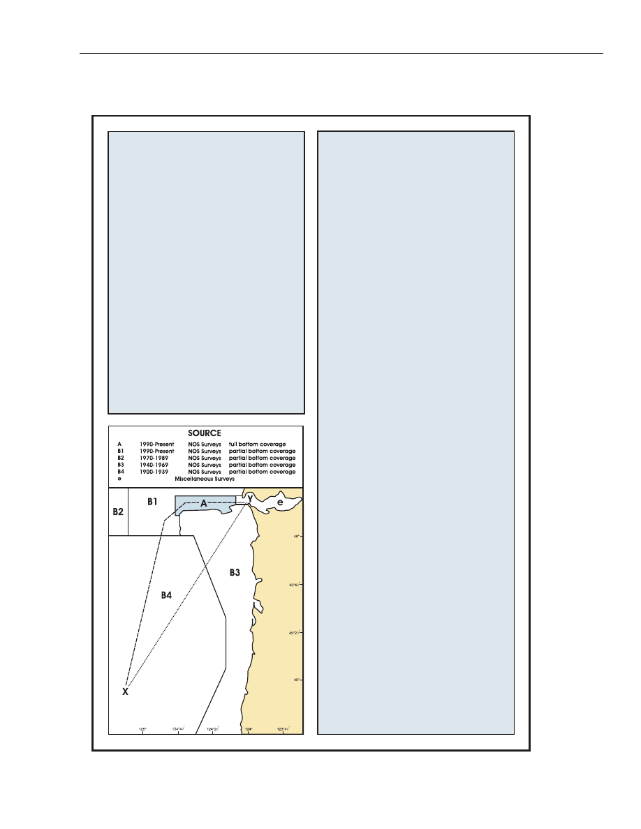
Source Diagrams
Referring to the accompanying sample Source
Diagram below and the previous discussion of
survey methods over time, transiting from Point
X to Point Y, along the track indicated by the
dotted line, would have the following information
available about the relative quality of the depth
information shown on the chart.
• Point X lies in an area surveyed by NOAA within
the 1900-1939 time period. The sounding data
would have been collected by leadline. Depths
between sounding points can only be inferred,
and undetected features might exist between the
sounding points in areas of irregular relief. Cau-
tion should be exercised.
• The transit then crosses an area surveyed by
NOAA within the 1940-1969 time period. The
sounding data would have been collected by
continuous recording single beam echo sounder.
It is possible that features could have been missed
between sounding lines, although echo sounders
record all depths along a sounding line with vary-
ing beam widths.

to differentially corrected Global Positioning System
(DGPS) satellite fixes.
(59)
From 1990 to the present, most surveys have been
conducted using either multibeam sonar systems or a
combination of side scan sonar and single beam echo
sounder systems to achieve full bottom coverage. The
term full bottom coverage refers to survey areas in
which the field party has acquired continuously re-
corded, high-resolution sonar data in overlapping
swaths. This sonar data, either multibeam bathymetry
or side scan imagery, have been analyzed in an attempt
to locate all hazards to navigation within the survey's
limits; all position data has been determined using
DGPS. NOAA began utilizing airborne light detection
and ranging systems (LIDAR) for near shore
bathymetric surveying in the late 1990s. This type of
survey method provided sounding data at a lower reso-
lution than sonar systems, thus making small obstruc-
tions and hazards difficult to identify. Although LIDAR
systems provide continuously recorded swath data, the
resulting sounding resolution is not dense enough for
the survey to be considered full bottom coverage. How-
ever, LIDAR surveys in which significant anomalies
have been further investigated using multibeam sonar
are considered adequate for the full bottom coverage
designation. Stand alone LIDAR surveys are depicted
on the Source Diagram as partial bottom coverage ar-
eas.
(60)
Although full bottom coverage surveys are not fea-
sible in all areas, this method is typically preferred over
leadline, single beam echo sounder, and LIDAR tech-
nologies. Full bottom coverage surveys typically extend
inshore to depths of 4-8 meters (13-26 feet). Due to
scaling factors, a full bottom coverage survey area may
appear to extend further inshore once depicted on the
Source Diagram. Sounding data in water depths of ap-
proximately 4-6 meters (13-19½ feet) or less (8 meters
(26 feet) or less in Alaskan waters) has typically been
acquired using a partial bottom coverage method. Cau-
tion and prudent seamanship should be used when
transiting these near shore areas.
(61)
The spacing of sounding lines required to survey an
area using a single beam echo sounder depends on sev-
eral factors; such as water depths, bottom configura-
tion, survey scale, general nature of the area, and the
purpose of the survey. For example, a 1:10,000-scale
6
■ Chapter 1
■
Volume 5
Bottom Coverage Comparison by Survey Method
Single Beam (1940’s - 1980’s)
Leadline (pre 1940)
Multibeam (1990’s - present)

survey conducted in an estuary will typically have
100-meter line spacing requirements, but may be re-
duced to 50 meters or less to adequately develop an ir-
regular bottom, shoal, or some other feature that may
present a hazard to navigation. Also, hydrographic pro-
ject instructions for surveys may have required line
spacing that deviates from these general specifications.
Corrections to charts
(62)
It is essential for navigators to keep charts cor-
rected through information published in the Notices to
Mariners.
(63)
NOAA’s “Nautical Chart Update” website allows the
mariner to update their nautical charts from one data-
base that includes information from NOAA, NGA U.S.
Notice to Mariners, U.S. Coast Guard Local Notices to
Mariners, and the Canadian Coast Guard Notices to
Mariners at: http://nauticalcharts.noaa.gov/mcd/up-
dates/LNM_NM.html.
Print On Demand Nautical Charts
(64)
Print On Demand (POD) Charts are updated weekly
by NOAA with the most current U.S. Coast Guard Local
Notice to Mariners, National Geospatial-Intelligence
Agency Notice to Mariners, and critical safety informa-
tion known to NOAA. They are available to the mariner
five to eight weeks before the conventional chart is
printed. POD charts are printed upon request and
shipped overnight to the mariner under a partnership
between NOAA and OceanGrafix, LLC. POD informa-
tion and a list of participating POD chart agents, can be
found at:
(65)
http://nauticalcharts.noaa.gov/pod/POD.htm and
(66)
http://www.oceangraphix.com.
(67)
Print on Demand charts are certified by NOAA for
navigational use.
Revised Reprint Nautical Charts
(68)
A revised reprint nautical chart provides mariners
with up-to-date critical information on nautical charts
by applying the critical corrections from all U.S. Coast
Guard Local Notice to Mariners (LNM) and National
Geospatial-Intelligence Agency Notice to Mariners
(NM) issued since the current edition date. A revised
reprint is published (rather than copies of the same
chart without the critical updates applied) when
printed stock of the current edition is low. Revised re-
prints are similar to NOAA's Print on Demand (POD)
charts but are lithographically printed according to tra-
ditional paper chart standards. A listing of upcoming new
editions and revised reprint charts published by NOAA is
available at http://www.nauticalcharts.noaa.gov.
Chart scale
(69)
The scale of a chart is the ratio of a given distance
on the chart to the actual distance that it represents on
the earth. For example, one unit of measurement on a
1:10,000 scale chart is equal to 10,000 of the same unit
on the earth's surface. Large-scale charts show greater
detail of a relatively small area. Small-scale charts
show less detail, but cover a larger area. Certain hydro-
graphic information may be omitted on smaller-scale
charts. Mariners should always obtain the larg-
est-scale coverage for near shore navigation.
(70)
The scales of nautical charts range from 1:2,500 to
about 1:5,000,000. Graphic scales are generally shown
on charts with scales of 1:80,000 or larger, and numeri-
cal scales are given on smaller scale charts. NOAA
charts are classified according to scale as follows:
(71)
Sailing charts, scales 1:600,000 and smaller, are for
use in fixing the mariner’s position approaching the
coast from the open ocean, or for sailing between dis-
tant coastwise ports. On such charts the shoreline and
topography are generalized and only offshore sound-
ings, principal lights, outer buoys, and landmarks visi-
ble at considerable distances are shown.
(72)
General charts, scales 1:150,000 to 1:600,000, are
for coastwise navigation outside of outlying reefs and
shoals.
(73)
Coast charts, scales 1:50,000 to 1:150,000, are for
inshore navigation leading to bays and harbors of con-
siderable width and for navigating large inland water-
ways.
(74)
Harbor charts, scales larger than 1:50,000, are for
harbors, anchorage areas, and the smaller waterways.
(75)
Special charts, various scales, cover the Intracoastal
waterways and miscellaneous small-craft areas.
U.S. Nautical Chart Numbering System
(76)
This chart numbering system, adopted by NOAA
and National Geospatial-Intelligence Agency, provides
for a uniform method of identifying charts published
by both agencies. Nautical charts published by the Na-
tional Geospatial-Intelligence Agency and by the Cana-
dian Hydrographic Service are identified in the Coast
Pilot by an asterisk preceding the chart number.
Blue tint in water areas
(77)
A blue tint is shown in water areas on many charts
to accentuate shoals and other areas considered dan-
gerous for navigation when using that particular chart.
Since the danger curve varies with the intended pur-
pose of a chart a careful inspection should be made to
determine the contour depth of the blue tint areas.
General Information
■
Chapter 1
■
7

Caution on bridge and cable clearances
(78)
For bascule bridges whose spans do not open to a
full vertical position, unlimited overhead clearance is
not available for the entire charted horizontal clear-
ance when the bridge is open, due to the inclination of
the drawspans over the channel.
(79)
The charted clearances of overhead cables are for
the lowest wires at mean high water unless otherwise
stated. Vessels with masts, stacks, booms, or antennas
should allow sufficient clearance under power cables to
avoid arcing.
(80)
Submarine cables and submerged pipelines cross
many waterways used by both large and small vessels,
but all of them may not be charted. For inshore areas,
they usually are buried beneath the seabed, but, for off-
shore areas, they may lie on the ocean floor. Warning
signs are often posted to warn mariners of their exis-
tence.
(81)
The installation of submarine cables or pipelines in
U.S. waters or the Continental Shelf of the United
States is under the jurisdiction of one or more Federal
agencies, depending on the nature of the installation.
They are shown on the charts when the necessary in-
formation is reported to NOAA and they have been rec-
ommended for charting by the responsible agency. The
chart symbols for submarine cable and pipeline areas
are usually shown for inshore areas, whereas, chart
symbols for submarine cable and pipeline routes may
be shown for offshore areas. Submarine cables and
pipelines are not described in the Coast Pilots.
(82)
In view of the serious consequences resulting from
damage to submarine cables and pipelines, vessel oper-
ators should take special care when anchoring, fishing,
or engaging in underwater operations near areas where
these cables or pipelines may exist or have been re-
ported to exist. Mariners are also warned that the areas
where cables and pipelines were originally buried may
have changed and they may be exposed; extreme cau-
tion should be used when operating vessels in depths of
water comparable to the vessel’s draft.
(83)
Certain cables carry high voltage, while many pipe-
lines carry natural gas under high pressure or petro-
leum products. Electrocution, fire, or explosion with
injury, loss of life, or a serious pollution incident could
occur if they are broached.
(84)
Vessels fouling a submarine cable or pipeline
should attempt to clear without undue strain. Anchors
or gear that cannot be cleared should be slipped, but no
attempt should be made to cut a cable or a pipeline.
Artificial obstructions to navigation
(85)
Disposal areas are designated by the U.S. Army
Corps of Engineers for depositing dredged material
where existing depths indicate that the intent is not to
cause sufficient shoaling to create a danger to surface
navigation. The areas are charted without blue tint,
and soundings and depth curves are retained.
(86)
Disposal Sites are areas established by Federal reg-
ulation (40 CFR 220 through 229) in which dumping
of dredged and fill material and other nonbuoyant ob-
jects is allowed with the issuance of a permit. Dumping
of dredged and fill material is supervised by the Corps
of Engineers and all other dumping by the Environ-
mental Protection Agency (EPA). (See U.S. Army Corps
of Engineers and Environmental Protection Agency,
this chapter, and Appendix A for office addresses.)
(87)
Dumping Grounds are also areas that were estab-
lished by Federal regulation (33 CFR 205). However,
these regulations have been revoked and the use of the
areas discontinued. These areas will continue to be
shown on nautical charts until such time as they are no
longer considered to be a danger to navigation.
(88)
Disposal Sites and Dumping Grounds are rarely
mentioned in the Coast Pilot, but are shown on nauti-
cal charts. Mariners are advised to exercise caution in
and in the vicinity of all dumping areas.
(89)
Spoil areas are for the purpose of depositing
dredged material, usually near and parallel to dredged
channels. Spoil areas are usually charted from survey
drawings from U.S. Army Corps of Engineers af-
ter-dredging surveys, though they may originate from
private or other Government agency surveys. On nauti-
cal charts, spoil areas are tinted blue, labeled and have
all soundings and depth curves omitted from within
their boundaries. Spoil areas present a hazard to navi-
gation and even the smallest craft should avoid
crossing them.
(90)
Fish havens are artificial shelters constructed of
various materials including rocks, rubble, derelict
barges/oil rigs and specially designed precast struc-
tures. This material is placed on the sea floor to simu-
late natural reefs and attract fish. Fish havens are often
located near fishing ports or major coastal inlets and
are usually considered hazards to shipping. Before
such a reef may be built, the U.S Army Corps of Engi-
neers must issue a permit specifying the location and
depth over the reef. Constructed of rigid material and
projecting above the bottom, they can impede surface
navigation and therefore represent an important fea-
ture for charting. Fish havens may be periodically al-
tered by the addition of new material, thereby possibly
increasing the hazard. They are outlined and labeled on
charts and show the minimum authorized depth when
known. Fish havens are tinted blue if they have a mini-
mum authorized depth of 11 fathoms or less. If the
minimum authorized depth is unknown and they are in
depths greater than 11 fathoms, they are considered a
danger to navigation. Navigators should be cautious
8
■ Chapter 1
■
Volume 5

about passing over fish havens or anchoring in their
vicinity.
(91)
Fishtrap areas are areas established by the U.S.
Army Corps of Engineers, or State or local authority, in
which traps may be built and maintained according to
established regulations. The fish stakes which may exist
in these areas are obstructions to navigation and may
be dangerous. The limits of fishtrap areas and a cau-
tionary note are usually charted. Navigators should
avoid these areas.
Local magnetic disturbances
(92)
If measured values of magnetic variation differ
from the expected (charted) values by several degrees, a
magnetic disturbance note will be printed on the chart.
The note will indicate the location and magnitude of
the disturbance, but the indicated magnitude should
not be considered as the largest possible value that may
be encountered. Large disturbances are more fre-
quently detected in the shallow waters near land
masses than on the deep sea. Generally, the effect of a
local magnetic disturbance diminishes rapidly with
distance, but in some locations there are multiple
sources of disturbances and the effects may be distrib-
uted for many miles.
Compass roses on charts
(93)
Each compass rose shows the date, magnetic varia-
tion, and the annual change in variation. Prior to the
new edition of a nautical chart, the compass roses are
reviewed. Corrections for annual change and other re-
visions may be made as a result of newer and more ac-
curate information. On some general and sailing
charts, the magnetic variation is shown by isogonic
lines in addition to the compass roses.
Echo soundings
(94)
Ship’s echo sounders may indicate small variations
from charted soundings; this may be due to the fact that
various corrections (instrument corrections, settlement
and squat, draft, and velocity corrections) are made to
echo soundings in surveying which are not normally
made in ordinary navigation, or to observational errors
in reading the echo sounder. Instrument errors vary
between different equipment and must be determined
by calibration aboard ship. Most types of echo sounders
are factory calibrated for a velocity of sound in water of
800 fathoms per second, but the actual velocity may
differ from the calibrated velocity by as much as 5 per-
cent, depending upon the temperature and salinity of
the waters in which the vessel is operating; the highest
velocities are found in warm, highly saline water, and
the lowest in icy freshwater. Velocity corrections for
these variations are determined and applied to echo
soundings during hydrographic surveys. All echo
soundings must be corrected for the vessel’s draft, un-
less the draft observation has been set on the echo
sounder.
(95)
Observational errors include misinterpreting false
echoes from schools of fish, seaweed, etc., but the most
serious error which commonly occurs is where the
depth is greater than the scale range of the instrument;
a 400–fathom scale indicates 15 fathoms when the
depth is 415 fathoms. Caution in navigation should be
exercised when wide variations from charted depths
are observed.
Electronic Navigational Chart (NOAA ENC
Ò
)
(96)
The NOAA Electronic Navigational Charts (ENCs)
are vector-based digital files that give information
about individual charted features. NOAA ENCs are
composed of information layers that can be viewed sep-
arately such as aids to navigation, soundings and
shoreline. They are intended for use in electronic
charting systems (ECS) as well as Electronic Chart Dis-
play and Information Systems (ECDIS). NOAA ENCs
are available free of charge at:
http://nauticalcharts.noaa.gov/mcd/enc/index.htm.
NOTICES TO MARINERS
(97)
Notices to Mariners are published to advise opera-
tors of marine information affecting the safety of navi-
gation. The notices include changes in aids to
navigation, depths in channels, bridge and overhead
cable clearances, reported dangers, and other useful
marine information. They should be used routinely for
updating the latest editions of nautical charts and re-
lated publications.
(98)
Local Notices to Mariners are issued by each Coast
Guard District Commander for the waters under his ju-
risdiction. (See Appendix A for Coast Guard district(s)
covered by this volume.) These notices are usually pub-
lished weekly and are available at:
http://www.navcen.uscg.gov/.
(99)
U.S. Notice to Mariners, published weekly by the
National Geospatial-Intelligence Agency, are prepared
jointly with NOAA and the Coast Guard. These notices
contain selected items from the Local Notices to Mari-
ners and other reported marine information required
by oceangoing vessels operating in both foreign and do-
mestic waters. Special items covering a variety of sub-
jects and generally not discussed in the Coast Pilot or
shown on nautical charts are published annually in No-
tice to Mariners No. 1. These items are important to the
mariner and should be read for future reference. These
General Information
■
Chapter 1
■
9

notices are available at:
http://msi.nga.mil/NGAPortal/MSI.portal.
(100)
All active Notices to Mariners affecting Tide and/or
Tidal Current Predictions at the date of printing are
published in the Tide Table and the Tidal Current Ta-
bles annually.
(101)
Marine Broadcast Notices to Mariners are made by
the Coast Guard to report deficiencies and important
changes in aids to navigation. (See Radio Navigation
Warnings and Weather, this chapter.)
(102)
Vessels operating within the limits of the Coast
Guard districts can obtain information affecting NOAA
charts and related publications from the Local Notices
to Mariners. Small craft using the Intracoastal Water-
way and other waterways and small harbors within the
United States that are not normally used by oceangoing
vessels will require the Local Notices to Mariners to
keep charts and related publications up-to-date.
AIDS TO NAVIGATION
Reporting of defects in aids to navigation
(103)
Promptly notify the nearest Coast Guard District
Commander if an aid to navigation is observed to be
missing, sunk, capsized, out of position, damaged, ex-
tinguished, or showing improper characteristics.
(104)
It is unlawful to establish or maintain any aid simi-
lar to those maintained by the U.S. Coast Guard with-
out first obtaining permission from the Coast Guard
District Commander. In the Great Lakes, applications
should be submitted through the Cleveland District Of-
fice. The licensed officer in command of a vessel which
collides with any aid must report the fact promptly to
the nearest U.S. Coast Guard Sector.
Lights
(105)
The range of visibility of lights as given in the Light
Lists and as shown on the charts is the Nominal range,
which is the maximum distance at which a light may be
seen in clear weather (meteorological visibility of 10
nautical miles) expressed in nautical miles. The Light
Lists give the Nominal ranges for all Coast Guard
lighted aids except range and directional lights.
(106)
Luminous range is the maximum distance at
which a light may be seen under the existing visibility
conditions. By use of the diagram in the Light Lists,
Luminous range may be determined from the known
Nominal range, and the existing visibility conditions.
Both the Nominal and Luminous ranges do not take
into account elevation, observer’s height of eye, or the
curvature of the earth.
(107)
Geographic range is a function of only the curva-
ture of the earth and is determined solely from the
heights above sea level of the light and the observer’s
eye; therefore, to determine the actual Geographic
range for a height of eye, the Geographic range must be
corrected by a distance corresponding to the height dif-
ference, the distance correction being determined
from a table of “distances of visibility for various
heights above sea level.” (See Light List or Appendix B.)
(108)
The maximum distances at which lights can be
seen may at times be increased by abnormal atmo-
spheric refraction and may be greatly decreased by un-
favorable weather conditions such as fog, rain, haze, or
smoke. All except the most powerful lights are easily
obscured by such conditions. In some conditions of the
atmosphere white lights may have a reddish hue. Dur-
ing weather conditions which tend to reduce visibility,
colored lights are more quickly lost to sight than are
white lights. Navigational lights should be used with
caution because of the following conditions that may
exist;
(109)
A light may be extinguished and the fact not re-
ported to the Coast Guard for correction, or a light may
be located in an isolated area where it will take time to
correct.
(110)
In regions where ice conditions prevail the lantern
panes of unattended lights may become covered with
ice or snow, which will greatly reduce the visibility and
may also cause colored lights to appear white.
(111)
Brilliant shore lights used for advertising and other
purposes, particularly those in densely populated areas,
make it difficult to identify a navigational light.
(112)
At short distances flashing lights may show a faint
continuous light between flashes.
(113)
The distance of an observer from a light cannot be
estimated by its apparent intensity. The characteristics
of lights in an area should always be checked in order
that powerful lights visible in the distance will not be
mistaken for nearby lights showing similar character-
istics at low intensity such as those on lighted buoys.
(114)
The apparent characteristic of a complex light may
change with the distance of the observer, due to color
and intensity variations among the different lights of
the group. The characteristic as charted and shown in
the Light List may not be recognized until nearer the
light.
(115)
Motion of a vessel in a heavy sea may cause a light
to alternately appear and disappear, and thus give a
false characteristic.
(116)
Where lights have different colored sectors, be
guided by the correct bearing of the light; do not rely
on being able to accurately observe the point at which
the color changes. On either side of the line of demar-
cation of colored sectors there is always a small arc of
uncertain color.
10
■ Chapter 1
■
Volume 5

(117)
On some bearings from the light, the range of visi-
bility of the light may be reduced by obstructions. In
such cases, the obstructed arc might differ with height
of eye and distance. When a light is cut off by adjoining
land and the arc of visibility is given, the bearing on
which the light disappears may vary with the distance
of the vessel from which observed and with the height
of eye. When the light is cut off by a sloping hill or point
of land, the light may be seen over a wider arc by a ship
far off than by one close to.
(118)
Arcs of circles drawn on charts around a light are
not intended to give information as to the distance at
which it can be seen, but solely to indicate, in the case
of lights which do not show equally in all directions,
the bearings between which the variation of visibility
or obscuration of the light occurs.
(119)
Lights of equal candlepower but of different colors
may be seen at different distances. This fact should be
considered not only in predicting the distance at which
a light can be seen, but also in identifying it.
(120)
Lights should not be passed close aboard, because
in many cases riprap mounds are maintained to protect
the structure against ice damage and scouring action.
(121)
Many prominent towers, tanks, smokestacks,
buildings, and other similar structures, charted as
landmarks, display flashing and/or fixed red aircraft ob-
struction lights. Lights shown from landmarks are
charted only when they have distinctive characteristics
to enable the mariner to positively identify the location
of the charted structure.
Articulated lights
(122)
An articulated light is a vertical pipe structure sup-
ported by a submerged buoyancy chamber and at-
tached by a universal coupling to a weighted sinker on
the seafloor. The light, allowed to move about by the
universal coupling, is not as precise as a fixed aid. How-
ever, it has a much smaller watch circle than a conven-
tional buoy, because the buoyancy chamber tends to
force the pipe back to a vertical position when it heels
over under the effects of wind, wave, or current.
(123)
Articulated lights are primarily designed to mark
narrow channels with greater precision than conven-
tional buoys.
Daybeacons
(124)
Daybeacons are unlighted aids affixed to stationary
structures. They are marked with dayboards for day-
time identification. The dayboards aid navigation by
presenting one of several standard shapes and colors
which have navigational significance. Dayboards are
sometimes referred to as daymarks.
(125)
Daybeacons are found on-shore and in shallow wa-
ter. They are frequently used to mark channel edges.
Articulated daybeacons
(126)
Articulated daybeacons are similar to articulated
lights, described above, except they are unlighted.
Buoys
(127)
The aids to navigation depicted on charts comprise
a system consisting of fixed and floating aids with vary-
ing degrees of reliability. Therefore, prudent mariners
will not rely solely on any single aid to navigation, par-
ticularly a floating aid.
(128)
The approximate position of a buoy is represented
by the dot or circle associated with the buoy symbol.
The approximate position is used because of practical
limitations in positioning and maintaining buoys and
their sinkers in precise geographical locations. These
limitations include, but are not limited to, inherent
imprecisions in position fixing methods, prevailing at-
mospheric and sea conditions, the slope of and the ma-
terial making up the seabed, the fact that buoys are
moored to sinkers by varying lengths of chain, and the
fact that buoy body and/or sinker positions are not un-
der continuous surveillance, but are normally checked
only during periodic maintenance visits which often
occur more than a year apart. The position of the buoy
body can be expected to shift inside and outside of the
charting symbol due to the forces of nature. The mari-
ner is also cautioned that buoys are liable to be carried
away, shifted, capsized, sunk, etc. Lighted buoys may be
extinguished or sound signals may not function as a re-
sult of ice, running ice or other natural causes, colli-
sions, or other accidents.
(129)
For the foregoing reasons, a prudent mariner must
not rely completely upon the charted position or opera-
tion of floating aids to navigation, but will also utilize
bearings from fixed objects and aids to navigation on
shore. Further, a vessel attempting to pass close aboard
always risks collision with a yawing buoy or with the
obstruction the buoy marks.
(130)
Buoys may not always properly mark shoals or
other obstructions due to shifting of the shoals or of
the buoys. Buoys marking wrecks or other obstruc-
tions are usually placed on the seaward or channelward
side and not directly over a wreck. Since buoys may be
located some distance from a wreck they are intended
to mark, and since sunken wrecks are not always static,
extreme caution should be exercised when operating in
the vicinity of such buoys.
Bridge lights and clearance gages
(131)
The Coast Guard regulates marine obstruction
lights and clearance gages on bridges across navigable
waters. Where installed, clearance gages are generally
vertical numerical scales, reading from top to bottom,
and show the actual vertical clearance between the
General Information
■
Chapter 1
■
11

existing water level and the lowest point of the bridge
over the channel; the gages are normally on the
right-hand pier or abutment of the bridge, on both the
upstream and downstream sides.
(132)
Bridge lights are fixed red or green, and are pri-
vately maintained; they are generally not charted or de-
scribed in the text of the Coast Pilot. All bridge piers
(and their protective fenders) and abutments which are
in or adjacent to a navigation channel are marked on all
channel sides by red lights. On each channel span of a
fixed bridge, there is a range of two green lights mark-
ing the center of the channel and a red light marking
both edges of the channel, except that when the mar-
gins of the channel are confined by bridge piers, the red
lights on the span are omitted, since the pier lights
then mark the channel edges; for multiplespan fixed
bridges, the main-channel span may also be marked by
three white lights in a vertical line above the green
range lights.
(133)
On all types of drawbridges, one or more red lights
are shown from the drawspan (higher than the pier
lights) when the span is closed; when the span is open,
the higher red lights are obscured and one or two green
lights are shown from the drawspan, higher than the
pier lights. The number and location of the red and
green lights depend upon the type of drawbridge.
(134)
Bridges and their lighting, construction and main-
tenance are set forth in 33 CFR 114, 115, 116, and
118, (not carried in this Coast Pilot). Aircraft obstruc-
tion lights prescribed by the Federal Aviation Adminis-
tration may operate at certain bridges.
Sound signals
(135)
Caution should be exercised in the use of sound
signals for navigation purposes. They should be consid-
ered solely as warning devices.
(136)
Sound travels through the air in a variable manner,
even without the effects of wind; and, therefore, the
hearing of sound signals cannot be implicitly relied
upon.
(137)
Experience indicates that distances must not be
judged only by the intensity of the sound; that occa-
sionally there may be areas close to a sound signal in
which it is not heard; and that fog may exist not far
from a station, yet not be seen from it, so the signal may
not be operating. It is not always possible to start a
sound signal immediately when fog is observed.
Caution, channel markers
(138)
Lights, daybeacons, and buoys along dredged chan-
nels do not always mark the bottom edges. Due to local
conditions, aids may be located inside or outside the
channel limits shown by dashed lines on a chart. The
Light List tabulates the offset distances for these aids in
many instances.
(139)
Aids may be moved, discontinued, or replaced by
other types to facilitate dredging operations. Mariners
should exercise caution when navigating areas where
dredges with auxiliary equipment are working.
(140)
Temporary changes in aids are not included on the
charts.
Light Lists
(141)
Light Lists, published by the Coast Guard, describe
aids to navigation, consisting of lights, sound signals,
buoys, daybeacons, and electronic aids, in United
States (including Puerto Rico and U.S. Virgin Islands)
and contiguous Canadian waters. Light Lists are for
sale by the Government Printing Office (see Appendix A
for address) and by sales agents in the principal sea-
ports.
Light
Lists
are
also
available
at
http://www.navcen.uscg.gov/. Mariners should refer to
these publications for detailed information regarding
the characteristics and visibility of lights, and the de-
scriptions of light structures, buoys, sound signals, and
electronic aids.
ELECTRONIC POSITIONING SYSTEMS
(142)
Global Positioning System (GPS) permits land,
sea, and airborne users to determine their three dimen-
sional position, velocity, and time, 24 hours a day in all
weather, anywhere in the world. The basic system is de-
fined as a constellation of satellites, the navigation pay-
loads which produce the GPS signals, ground stations,
data links, and associated command and control facili-
ties which are operated and maintained by the Depart-
ment of Defense. Please report GPS problems or
anomalies at http://www.navcen.uscg.gov/ or contact
the USCG Navigation Information Service at 703-313-
5900.
(143)
The U.S. Coast Guard Navigation Center (NAVCEN)
operates the Coast Guard Maritime Differential GPS
(DGPS) Service. The Service broadcasts correction
signals on marine radiobeacon frequencies to improve
the accuracy of and integrity to GPS-derived positions.
Typically, the positional error of a DGPS position is 1 to
3 meters, greatly enhancing harbor entrance and ap-
proach navigation. The System provides service for
coastal coverage of the continental U.S., the Great
Lakes, Puerto Rico, portions of Alaska and Hawaii, and
a greater part of the Mississippi River Basin.
(144)
Wide Area Augmentation System (WAAS) em-
ploys ground based master and reference stations to
measure variations in GPS satellite signals. These mea-
surements are sent to WAAS satellites that broadcast
12
■ Chapter 1
■
Volume 5

the correction messages back to Earth, for improved
position accuracy on WAAS-enabled GPS receivers.
LORAN-C
(145)
LORAN, an acronym for LOng RAnge Navigation,
was an electronic aid to navigation consisting of
shore-based radio transmitters. In accordance with the
DHS Appropriations Act, the U.S. Coast Guard has ter-
minated the transmission of all LORAN-C signals as of
August 2010, rendering them unusable and perma-
nently
discontinued.
For
more
details,
view
http://www.navcen.uscg.gov/.
The
Coast
Guard
strongly
urges
mariners
accustomed
to
using
LORAN-C for navigation to shift to a GPS navigation
system and become familiar with its operation. NOAA is
removing LORAN-C lines of position from all of its
charts as new editions are published.
DISTRESS: COMMUNICATION PROCEDURES
Coast Guard search and rescue operations
(146)
The Coast Guard conducts and/or coordinates
search and rescue operations for surface vessels or air-
craft that are in distress or overdue. Search and Rescue
vessels and aircraft have special markings, including a
wide slash of red-orange and a small slash of blue on
the forward portion of the hull or fuselage. Other parts
of aircraft, normally painted white, may have other ar-
eas painted red to facilitate observation. The coopera-
tion of vessel operators with Coast Guard helicopters,
fixed-wing aircraft, and vessels may mean the differ-
ence between life and death for some seaman or avia-
tor; such cooperation is greatly facilitated by the prior
knowledge on the part of vessel operators of the opera-
tional requirements of Coast Guard equipment and
personnel, of the international distress signals and pro-
cedures, and of good seamanship.
(147)
Note: Distress and other calls to Coast Guard com-
munication stations may be made on any of the follow-
ing HF single sideband radiotelephone channels: 4125
kHz, 6215 kHz, 8291 kHz, or 12290 kHz.
International distress signals
(148)
(1) A signal made by radiotelegraphy or by any
other signaling method consisting of the group “SOS”
in Morse Code.
(149)
(2) A signal sent by radiotelephony consisting of
the spoken word “MAYDAY.”
(150)
(3) The International Flag Code Signal of NC.
(151)
(4) A signal consisting of a square flag having above
or below it a ball or anything resembling a ball.
(152)
(5) Flames on the craft (as from a burning oil bar-
rel, etc.)
(153)
(6) A rocket parachute flare or hand flare showing a
red light.
(154)
(7) Rockets or shells, throwing red stars fired one
at a time at short intervals.
(155)
(8) Orange smoke, as emitted from a distress flare.
(156)
(9) Slowly and repeatedly raising and lowering
arms outstretched to each side.
(157)
(10) A gun or other explosive signal fired at inter-
vals of about 1 minute.
(158)
(11) A continuous sounding of any fog-signal appa-
ratus.
(159)
(12) The radiotelegraph alarm signal.
(160)
(13) The radiotelephone alarm signal.
(161)
(14) Signals transmitted by emergency position-in-
dicating radiobeacons.
(162)
(15) A piece of orange-colored canvas with either a
black square and circle or other appropriate symbol
(for identification from the air).
(163)
(16) A dye marker.
Radio distress procedures
(164)
Distress calls are made on 2182 kHz or VHF-FM
channel 16 (MAYDAY). For less serious situations than
warrant the distress procedure, the urgency signal
PAN-PAN (PAHN-PAHN, spoken three times), or the
safety signal SECURITY (SAY-CURITAY, spoken three
times), for radiotelephony, are used as appropriate.
Since urgent and safety situations are less critical, only
the distress procedures for voice radiotelephone are de-
scribed. For complete information on emergency radio
procedures, see 47 CFR 80 or NGA Pub. 117. Complete
information on distress guards can be obtained from
Coast Guard District Commanders.
(165)
Distress calls indicate a vessel or aircraft is threat-
ened by grave and imminent danger and requests im-
mediate assistance. They have absolute priority over all
other transmissions. All stations which hear a distress
call must immediately cease any transmission capable
of interfering with the distress traffic and shall con-
tinue to listen on the frequency used for the emission
of the distress call. This call shall not be addressed to a
particular station, and acknowledgment of receipt shall
not be given before the distress message which follows
it is sent.
Radiotelephone distress communications
(166)
(1) The radiotelephone alarm signal (if available):
The signal consists of two audio tones, of different
pitch, transmitted alternately; its purpose is to attract
the attention of persons on radio watch or to actuate
automatic alarm devices. It may only be used to an-
nounce that a distress call or message is about to fol-
low.
(167)
(2) The distress call, consisting of:—
General Information
■
Chapter 1
■
13

(168)
the distress signal MAYDAY (spoken three times);
(169)
the words THIS IS (spoken once);
(170)
the call sign or name of the vessel in distress (spo-
ken three times).
(171)
(3) The distress message follows immediately and
consists of:
(172)
the distress signal MAYDAY;
(173)
the call sign and name of the vessel in distress;
(174)
particulars of its position (latitude and longitude,
or true bearing and distance from a known geograph-
ical position);
(175)
the nature of the distress;
(176)
the kind of assistance desired;
(177)
the number of persons aboard and the condition of
any injured;
(178)
present seaworthiness of vessel;
(179)
description of the vessel (length; type; cabin;
masts; power; color of hull, superstructure, trim; etc.);
(180)
any other information which might facilitate the
rescue, such as display of a surface-to-air identification
signal or a radar reflector;
(181)
your listening frequency and schedule;
(182)
THIS IS (call sign and name of vessel in distress)
OVER.
(183)
(4) Acknowledgment of receipt of a distress mes-
sage: If a distress message is received from a vessel
which is definitely in your vicinity, immediately ac-
knowledge receipt. If it is not in your vicinity, allow a
short interval of time to elapse before acknowledging,
in order to allow vessels nearer to the vessel in distress
to acknowledge receipt without interference. However,
in areas where reliable communications with one or
more shore stations are practicable, all vessels may defer
this acknowledgment for a short interval so that a
shore station may acknowledge receipt first. The ac-
knowledgment of receipt of a distress is given as fol-
lows:
(184)
the call sign or name of the vessel sending the dis-
tress (spoken three times);
(185)
the words THIS IS;
(186)
the call sign or name of acknowledging vessel (spo-
ken three times);
(187)
The words RECEIVED MAYDAY.
(188)
After the above acknowledgment, allow a momen-
tary interval of listening to insure that you will not in-
terfere with another vessel better situated to render
immediate assistance; if not, with the authority of the
person in charge of the vessel, transmit:
(189)
the word MAYDAY;
(190)
the call sign and name of distressed vessel;
(191)
the words THIS IS;
(192)
the call sign and name of your vessel;
(193)
your position (latitude and longitude, or true bear-
ing and distance from a known geographical position);
(194)
the speed you are proceeding towards, and the ap-
proximate time it will take to reach, the distressed ves-
sel. OVER.
(195)
(5) Further distress messages and other commu-
nications: Distress communications consist of all mes-
sages relating to the immediate assistance required by
the distressed vessel. Each distress communication
shall be preceded by the signal MAYDAY. The vessel in
distress or the station in control of distress communi-
cations may impose silence on any station which inter-
feres. The procedure is:—the words SEELONCE
MAYDAY (Seelonce is French for silence). Silence also
may be imposed by nearby mobile stations other than
the vessel in distress or the station in control of distress
communications. The mobile station which believes
that silence is essential may request silence by the fol-
lowing procedure:—the word SEELONCE, followed by
the word DISTRESS, and its own call sign.
(196)
(6) Transmission of the distress procedure by a
vessel or shore station not itself in distress: A vessel or
a shore station which learns that a vessel is in distress
shall transmit a distress message in any of the follow-
ing cases:
(197)
(a) When the vessel in distress is not itself able to
transmit the distress message.
(198)
(b) When a vessel or a shore station considers that
further help is necessary.
(199)
(c) When, although not in a position to render as-
sistance, it has heard a distress message that has not
been acknowledged.
(200)
In these cases, the transmission shall consist of:
(201)
the radiotelephone alarm signal (if available);
(202)
the words MAYDAY RELAY (spoken three times);
(203)
the words THIS IS;
(204)
the call sign and name of vessel (or shore station),
spoken three times.
(205)
When a vessel transmits a distress under these con-
ditions, it shall take all necessary steps to contact the
Coast Guard or a shore station which can notify the
Coast Guard.
(206)
(7) Termination of distress: When distress traffic
has ceased, or when silence is no longer necessary on
the frequency used for the distress traffic, the station in
control shall transmit on that frequency a message to
all stations as follows:
(207)
the distress signal MAYDAY;
(208)
the call TO ALL STATIONS, spoken three times;
(209)
the words THIS IS;
(210)
the call sign and name of the station sending the
message;
(211)
the time;
(212)
the name and call sign of the vessel in distress;
(213)
the words SEELONCE FEENEE (French for silence
finished).
14
■ Chapter 1
■
Volume 5

Optimize Radar Profile
(214)
Operators of disabled wooden craft and persons
adrift in rubber rafts or boats that are, or may consider
themselves to be, the object of a search, should hoist on
a halyard or otherwise place aloft as high as possible
any metallic object that would assist their detection by
radar. Coast Guard cutters and aircraft are radar
equipped and thus are able to continue searching in
darkness and during other periods of low visibility. It is
advisable for coastal fishing boats, yachts, and other
small craft to have efficient radar reflectors perma-
nently installed aboard the vessel.
File cruising schedules
(215)
Small-craft operators should prepare a cruising
plan before starting on extended trips and leave it
ashore with a yacht club, marina, friend, or relative. It
is advisable to use a checking-in procedure by tele-
phone for each point specified in the cruising plan.
Such a trip schedule is vital for determining if a boat is
overdue and will assist materially in locating a missing
craft in the event search and rescue operations become
necessary.
DISTRESS: ASSISTANCE PROCEDURES
Surface ship procedures for assisting distressed
surface vessels
(216)
(1) The following immediate action should be
taken by each ship on receipt of a distress message:
(217)
(a) Acknowledge receipt and, if appropriate, re-
transmit the distress message;
(218)
(b) Immediately try to take D/F bearings during the
transmission of the distress message and maintain a
D/F watch on 2182 kHz;
(219)
(c) Communicate the following information to the
ship in distress:
(220)
(i) identity;
(221)
(ii) position;
(222)
(iii) speed and estimated time of arrival (ETA);
(223)
(iv) when available, true bearing of the ship in dis-
tress.
(224)
(d) Maintain a continuous listening watch on the
frequency used for the distress. This will normally be:
(225)
(i) 2182 kHz (radiotelephone).
(226)
(e) Additionally, maintain watch on VHF-FM chan-
nel 16 as necessary;
(227)
(f) Operate radar continuously;
(228)
(g) If in the vicinity of the distress, post extra look-
outs.
(229)
(2) The following action should be taken when pro-
ceeding to the area of distress:
(230)
(a) Plot the position, course, speed, and ETA of
other assisting ships.
(231)
(b) Attempt to construct an accurate “picture” of
the circumstances attending the casualty. The impor-
tant information needed is included under Distress
Signals and Communication Procedures, this chapter.
Should the ship in distress fail to transmit this infor-
mation, a ship proceeding to assist should request what
information is needed.
(232)
(3) The following on-board preparation while pro-
ceeding to the distress area should be considered:
(233)
(a) A rope (guest warp) running from bow to quar-
ter at the waterline on each side and secured by lizards
to the ship’s side to assist boats and rafts to secure
alongside;
(234)
(b) A derrick rigged ready for hoisting on each side
of the ship with a platform cargo sling, or rope net, se-
cured to the runner to assist the speedy recovery of ex-
hausted or injured survivors in the water;
(235)
(c) Heaving lines, ladders, and scramble net placed
ready for use along both sides of the ship on the lowest
open deck and possibly crew members suitably
equipped to enter the water and assist survivors;
(236)
(d) A ship’s liferaft made ready for possible use as a
boarding station;
(237)
(e) Preparations to receive survivors who require
medical assistance including the provision of stretchers;
(238)
(f) When own lifeboat is to be launched, any means
to provide communications between it and the parent
ship will prove to be of very great help;
(239)
(g) A line throwing appliance with a light line and a
heavy rope, ready to be used for making connection ei-
ther with the ship in distress or with survival craft.
Aircraft procedures for directing surface craft to
scene of distress incident
(240)
The following procedures performed in sequence
by an aircraft mean that the aircraft is directing a sur-
face craft toward the scene of a distress incident,
(241)
(a) Circling the surface craft at least once.
(242)
(b) Crossing the projected course of the surface
craft close ahead at low altitude, rocking the wings,
opening and closing the throttle, or changing the pro-
peller pitch.
(243)
(c) Heading in the direction in which the surface
craft is to be directed. The surface craft should ac-
knowledge the signal by changing course and following
the aircraft. If, for any reason, it is impossible to follow,
the surface craft should hoist the international code
flag NOVEMBER, or use any other signaling means
available to indicate this.
(244)
The following procedures performed by an aircraft
mean that the assistance of the surface craft is no lon-
ger required:
General Information
■
Chapter 1
■
15

(245)
(a) Crossing the wake of the surface craft close
astern at a low altitude, rocking the wings, opening and
closing the throttle or changing the propeller pitch.
(246)
Since modern jet-engined aircraft cannot make the
characteristic sound associated with opening and clos-
ing the throttle, or changing propeller pitch, ships
should be alert to respond to the signals without the
sounds, when jets or turboprop aircraft are involved.
Surface ship procedures for assisting aircraft in
distress
(247)
1. When an aircraft transmits a distress message by
radio, the first transmission is generally made on the
designated air/ground enroute frequency in use at the
time between the aircraft and aeronautical station. The
aircraft may change to another frequency, possibly an-
other enroute frequency or the aeronautical emer-
gency frequencies of 121.50 MHz or 243 MHz. In an
emergency, it may use any other available frequency to
establish contact with any land or mobile station.
(248)
2. There is liaison between Coast Radio Stations
aeronautical units, and land–based search and rescue
organizations. Merchant ships will ordinarily be in-
formed of aircraft casualties at sea by broadcast mes-
sages from Coast Radio Stations, made on the
international distress frequency of 2182 kHz. Ships
may, however, become aware of the casualty by receiv-
ing:
(249)
(a) An SOS message from an aircraft in distress
which is able to transmit on radiotelephone on 2182
kHz.
(250)
(b) A message from a SAR aircraft.
(251)
3. For the purpose of emergency communications
with aircraft, special attention is called to the possibil-
ity of conducting direct communications on 2182 kHz,
if both ship and aircraft are so equipped.
(252)
4. An aircraft in distress will use any means at its
disposal to attract attention, make known its position,
and obtain help, including some of the signals pre-
scribed by the applicable Navigation Rules.
(253)
5. Aircraft usually sink quickly (e.g. within a few
minutes). Every endeavor will be made to give ships an
accurate position of an aircraft which desires to ditch.
When given such a position, a ship should at once con-
sult any other ships in the vicinity on the best proce-
dure to be adopted. The ship going to the rescue should
answer the station sending the broadcast and give her
identity, position, and intended action.
(254)
6. If a ship should receive a distress message direct
from an aircraft, she should act as indicated in the im-
mediately preceding paragraph and also relay the mes-
sage to the nearest Coast Radio Station. Moreover, a
ship which has received a distress message direct from
an aircraft and is going to the rescue should take a
bearing on the transmission and inform the Coast Ra-
dio Station and other ships in the vicinity of the call
sign of the distressed aircraft and the time at which the
distress message was received, followed by the bearing
and time at which the signal ceased.
(255)
7. When an aircraft decides to ditch in the vicinity
of a ship, the ship should:
(256)
(a) Transmit homing bearings to the aircraft, or (if
so required) transmit signals enabling the aircraft to
take its own bearings.
(257)
(b) By day, make black smoke.
(258)
(c) By night, direct a searchlight vertically and turn
on all deck lights. Care must be taken not to direct a
searchlight toward the aircraft, which might dazzle the
pilot.
(259)
8. Ditching an aircraft is difficult and dangerous. A
ship which knows that an aircraft intends to ditch
should be prepared to give the pilot the following infor-
mation:
(260)
(a) Wind direction and force.
(261)
(b) Direction, height, and length of primary and
secondary swell systems.
(262)
(c) Other pertinent weather information.
(263)
The pilot of an aircraft will choose his own ditching
heading. If this is known by the ship, she should set
course parallel to the ditching heading. Otherwise the
ship should set course parallel to the main swell system
and into the wind component, if any.
(264)
9. A land plane may break up immediately on strik-
ing the water, and liferafts may be damaged. The ship
should, therefore, have a lifeboat ready for launching,
and if possible, boarding nets should be lowered from
the ship and heaving lines made ready in the ship and
the lifeboat. Survivors of the aircraft may have bright
colored lifejackets and location aids.
(265)
10. The method of recovering survivors must be
left to the judgment of the master of the ship carrying
out the rescue operation.
(266)
11. It should be borne in mind that military aircraft
are often fitted with ejection seat mechanisms. Nor-
mally, their aircrew will use their ejection seats, rather
than ditch. Should such an aircraft ditch, rather than
the aircrew bail out, and it becomes necessary to re-
move them from their ejection seats while still in the
aircraft, care should be taken to avoid triggering off the
seat mechanisms. The activating handles are invariably
indicated by red and or black/yellow coloring.
(267)
12. A survivor from an aircraft casualty who is re-
covered may be able to give information which will as-
sist in the rescue of other survivors. Masters are
therefore asked to put the following questions to survi-
vors and to communicate the answers to a Coast Radio
Station. They should also give the position of the
16
■ Chapter 1
■
Volume 5

rescuing ship and the time when the survivors were re-
covered.
(268)
(a) What was the time and date of the casualty?
(269)
(b) Did you bail out or was the aircraft ditched?
(270)
(c) If you bailed out, at what altitude?
(271)
(d) How many others did you see leave the aircraft
by parachute?
(272)
(e) How many ditched with the aircraft?
(273)
(f) How many did you see leave the aircraft after
ditching?
(274)
(g) How many survivors did you see in the water?
(275)
(h) What flotation gear had they?
(276)
(i) What was the total number of persons aboard
the aircraft prior to the accident?
(277)
(j) What caused the emergency?
Helicopter evacuation of personnel
(278)
Helicopter evacuation, usually performed by the
Coast Guard, is a hazardous operation to the patient
and to the flight crew, and should only be attempted in
event of very serious illness or injury. Provide the doctor
on shore with all the information you can concerning
the patient, so that an intelligent evaluation can be
made concerning the need for evacuation. Most rescue
helicopters can proceed less than 150 miles offshore (a
few new helicopters can travel 250 to 300 miles out to
sea), dependent on weather conditions and other vari-
ables. If an evacuation is necessary, the vessel must be
prepared to proceed within range of the helicopter, and
should be familiar with the preparations which are nec-
essary prior to and after its arrival.
(279)
When requesting helicopter assistance:
(280)
(1) Give the accurate position, time, speed, course,
weather conditions, sea conditions, wind direction and
velocity, type of vessel, and voice and CW frequency for
your ship.
(281)
(2) If not already provided, give complete medical
information including whether or not the patient is
ambulatory.
(282)
(3) If you are beyond helicopter range, advise your
diversion intentions so that a rendezvous point may be
selected.
(283)
(4) If there are changes to any items reported ear-
lier, advise the rescue agency immediately. Should the
patient die before the arrival of the helicopter, be sure
to advise those assisting you.
(284)
Preparations prior to the arrival of the helicopter:
(285)
(1) Provide continuous radio guard on 2182 kHz or
specified voice frequency, if possible. The helicopter
normally cannot operate CW.
(286)
(2) Select and clear the most suitable hoist area,
preferably aft on the vessel with a minimum of 50 feet
(15.2 meters) radius of clear deck. This must include
the securing of loose gear, awnings, and antenna wires.
Trice up running rigging and booms. If hoist is aft,
lower the flag staff.
(287)
(3) If the hoist is to take place at night, light the
pickup areas as well as possible. Be sure you do not
shine any lights on the helicopter, so that the pilot is
not blinded. If there are any obstructions in the vicin-
ity, put a light on them so the pilot will be aware of their
positions.
(288)
(4) Point searchlight vertically to aid the flight
crew in locating the ship and turn them off when the
helicopter is on the scene.
(289)
(5) Be sure to advise the helicopter of the location
of the pickup area on the ship before the helicopter ar-
rives, so that the pilot may make his approach to aft,
amidships, or forward, as required.
(290)
(6) There will be a high noise level under the heli-
copter, so voice communications on deck are almost
impossible. Arrange a set of hand signals among the
crew who will assist.
(291)
Hoist operations:
(292)
(1) If possible, have the patient moved to a position
as close to the hoist area as his condition will per-
mit–time is important.
(293)
(2) Normally, if a litter (stretcher) is required, it
will be necessary to move the patient to the special lit-
ter which will be lowered by the helicopter. Be prepared
to do this as quickly as possible. Be sure the patient is
strapped in, face up, and with a life jacket on (if his con-
dition will permit).
(294)
(3) Be sure that the patient is tagged to indicate
what medication, if any, was administered to him and
when it was administered.
(295)
(4) Have patient’s medical record and necessary pa-
pers in an envelope or package ready for transfer with
the patient.
(296)
(5) Again, if the patient’s condition permits, be sure
he is wearing a life jacket.
(297)
(6) Change the vessel’s course to permit the ship to
ride as easily as possible with the wind on the bow, pref-
erably on the port bow. Try to choose a course to keep
the stack gases clear of the hoist area. Once established,
maintain course and speed.
(298)
(7) Reduce speed to ease ship’s motion, but main-
tain steerageway.
(299)
(8) If you do not have radio contact with the heli-
copter, when you are in all respects ready for the hoist,
signal the helicopter in with a “come on” with your
hand, or at night by flashlight signals.
(300)
(9) Allow basket or stretcher to touch deck prior to
handling to avoid static shock.
General Information
■
Chapter 1
■
17

(301)
(10) If a trail line is dropped by the helicopter, guide
the basket or stretcher to the deck with the line; keep
the line free at all times. This line will not cause shock.
(302)
(11) Place the patient in basket, sitting with his
hands clear of the sides, or in the litter, as described
above. Signal the helicopter hoist operator when ready
for the hoist. Patient should signal by a nodding of the
head if he is able. Deck personnel give thumbs up.
(303)
(12) If it is necessary to take the litter away from
the hoist point, unhook the hoist cable and keep it free
for the helicopter to haul in. Do not secure cable or
trail line to the vessel or attempt to move stretcher
without unhooking.
(304)
(13) When patient is strapped into the stretcher,
signal the helicopter to lower the cable, attach cable to
stretcher sling (bridle), then signal the hoist operator
when the patient is ready to hoist. Steady the stretcher
so it will not swing or turn.
(305)
(14) If a trail line is attached to the basket or
stretcher, use it to steady the patient as he is hoisted.
Keep your feet clear of the line, and keep the line from
becoming entangled.
Medical advice and/or evacuation
(306)
In the event a master of a vessel requires medical
advice and/or there is a potential of evacuation the fol-
lowing should be volunteered by the master:
(307)
Vessel’s name and call sign.
(308)
Vessel’s position and time at position.
(309)
Vessel’s course, speed and next port and estimated
time of arrival (ETA).
(310)
Patient’s name, nationality, age, race and sex.
(311)
Patient’s respiration, pulse and temperature.
(312)
Patient’s symptoms and nature of illness.
(313)
Any known history of similar illness.
(314)
Location and type of pain.
(315)
Medical supplies carried on board vessel.
(316)
Medication given to patient.
(317)
Weather.
(318)
Communication schedule and frequency.
Coast Guard droppable, floatable pumps
(319)
The Coast Guard often provides vessels in distress
with emergency pumps by either making parachute
drops, by lowering on helicopter hoist, or by delivering
by vessel. The most commonly used type of pump co-
mes complete in a sealed aluminum drum about half
the size of a 50-gallon oil drum. One single lever on top
opens it up. Smoking is cautioned against due to the
possible presence of gas fumes inside the can. The
pump will draw about 90 gallons per minute. There
should be a waterproof flashlight on top of the pump
for night use. Operating instructions are provided in-
side the pump container.
(320)
Preparations for being towed by Coast Guard:
(321)
(1) Clear the forecastle area as well as you can.
(322)
(2) If a line-throwing gun is used, keep everyone
out of the way until line clears the boat. The Coast
Guard vessel will blow a police whistle or otherwise
warn you before firing.
(323)
(3) Have material ready for chafing gear.
Medical advice
(324)
Free medical advice is furnished to seamen by radio
through the cooperation of Governmental and com-
mercial radio stations whose operators receive and re-
lay messages prefixed RADIOMEDICAL from ships at
sea to the U.S. Coast Guard and/or directly to a hospital
and then radio the medical advice back to the ships.
(See Appendix A for list of radio stations that provide
this service.)
EMERGENCY POSITION INDICATING
RADIOBEACONS (EPIRB)
(325)
Emergency Position Indicating Radiobeacons
(EPIRBs), are designed to save your life if you get into
trouble by alerting rescue authorities and indicating
your location. EPIRB types are described in the accom-
panying table.
(326)
406 MHz EPIRBs (Category I, II): The 406 MHz
EPIRB was designed to operate with satellites. The sig-
nal frequency (406 MHz) has been designated interna-
tionally
to
be
used
only
for
distress.
Other
communications and interference are not allowed on
this frequency. Its signal allows a satellite local user
terminal to accurately locate the EPIRB and identify
the vessel (the signal is encoded with the vessel's iden-
tity) anywhere in the world (there is no range limita-
tion). These devices are detectable not only by
COSPAS-SARSAT satellites which are polar orbiting,
but also by geostationary GOES weather satellites.
EPIRBs detected by the GEOSAR system, consisting of
GOES and other geostationary satellites, send rescue
18
■ Chapter 1
■
Volume 5
EPIRB Types
Type
Frequency
Description
Cat I
406 MHz
Float-free, automatically activated
EPIRB. Detectable by satellite
anywhere in the world. Recognized
by the Global Maritime and Distress
Safety System (GMDSS).
Cat II
406 MHz
Similar to Category I, except is
manually activated. Some models
are also water activated.

authorities an instant alert, but without location infor-
mation unless the EPIRB is equipped with an integral
GPS receiver. EPIRBs detected by COSPAS-SARSAT
(e.g. TIROS N) satellites provide rescue authorities lo-
cation of distress, but location and sometimes alerting
may be delayed as much as an hour or two. These
EPIRBs also include a 121.5 MHz homing signal, allow-
ing aircraft and rescue craft to quickly find the vessel in
distress. These are the only type of EPIRB which must
be certified by Coast Guard approved independent labo-
ratories before they can be sold in the United States.
(327)
A new type of 406 MHz EPIRB, having an integral
GPS navigation receiver, became available in 1998.
This EPIRB will send accurate location as well as iden-
tification information to rescue authorities immedi-
ately upon activation through both geostationary
(GEOSAR) and polar orbiting satellites. These types of
EPIRB are the best you can buy.
(328)
406 MHz emergency locating transmitters (ELTs)
for aircraft are currently available and 406 MHz per-
sonnel locating beacons (PLBs) are also available.
(329)
The Coast Guard recommends you purchase a 406
MHz EPIRB, preferably one with an integral GPS navi-
gation receiver. A Cat I EPIRB should be purchased if it
can be installed properly.
(330)
Proper registration of your 406 MHz EPIRB is in-
tended to save your life, and is mandated by Federal
Communications Commission regulations; the Coast
Guard is enforcing this FCC registration rule.
(331)
If you purchase a new or a used 406 MHz EPIRB,
you MUST register it with NOAA. If you change your
boat, your address, or your primary phone number, you
MUST re-register your EPIRB with NOAA. If you sell
your EPIRB, make sure the purchaser re-registers the
EPIRB, or you may be called by the Coast Guard if it
later becomes activated. An FCC ship station license is
no longer required to purchase or carry an EPIRB.
Download or request 406 MHz EPIRB registration
forms from http://www.sarsat.noaa.gov/beacon.html,
and mail or fax completed forms to:
(332)
Beacon Registration
(333)
NOAA/NESDIS
(334)
NSOF, E/SP3
(335)
4231 Suitland Road
(336)
Suitland, MD 20746
(337)
(fax: 301-817-4565)
(338)
or call toll free at 1-888-212-SAVE (1-888-212-7283)
for further information or a copy of the registration
form. From outside the U.S., call: 1-301-457-5430 or
fax: 301-568-8649 for further information. Forms may
be requested by phone or fax, or downloaded by com-
puter (above). There is no charge for this service. IT
MAY SAVE YOUR LIFE.
The COSPAS-SARSAT system
(339)
COSPAS: Space System for Search of Distress Ves-
sels (a Russian acronym); SARSAT: Search and Rescue
Satellite-Aided Tracking. COSPAS-SARSAT is an inter-
national satellite system designed to provide distress
alert and location data to assist search and rescue
(SAR) operations, using satellites and ground facilities
to detect and locate the signals of distress beacons op-
erating on 121.5 and 406 MHz (Megahertz). The system
provides distress alert and location data to Rescue Co-
ordination Centers for 121.5 MHz beacons within the
coverage area of ground stations (Local User Termi-
nals–LUTs), and for 406 MHz beacons activated any-
where in the world. The goal of the system is to support
all organizations in the world with responsibility for
SAR operations.
Testing EPIRBs
(340)
The Coast Guard urges those owning EPIRBs to pe-
riodically examine them for water tightness, battery ex-
piration date and signal presence. FCC rules allow
Class A, B, and S EPIRBs to be turned on briefly (for
three audio sweeps, or one second only) during the first
five minutes of each hour. Signal presence can be de-
tected by an FM radio tuned to 99.5 MHz, or an AM ra-
dio tuned to any vacant frequency and located close to
an EPIRB. 406 MHz EPIRBs can be tested through its
self-test function, which is an integral part of the device.
(341)
Radar beacons (Racons) are low-powered radio
transceivers that operate in the marine radar X-band
frequencies. When activated by a vessel’s radar signal,
Racons provide a distinctive visible display on the ves-
sel’s radarscope from which the range and bearing to
the beacon may be determined. (See Light List and
NGA Pub. 117 for details.)
RADIO: NAVIGATION WARNINGS,
INFORMATION AND WEATHER
(342)
Marine radio warnings and weather are dissemi-
nated by many sources and through several types of
transmissions. U.S. Coast Guard NAVTEX, high-fre-
quency (HF) narrow-band direct printing (radio telex),
HF radiofacsimile, and radiotelephone broadcasts of
maritime safety information are summarized here.
(For complete information on radio warnings and
weather see NGA Pub. 117 and the National Weather
Service publication Worldwide Marine Radiofacsimile
Broadcast Schedules.)
Coast Guard radio stations
(343)
Coast Guard radio stations provide urgent, safety,
and scheduled marine information broadcasts with
General Information
■
Chapter 1
■
19
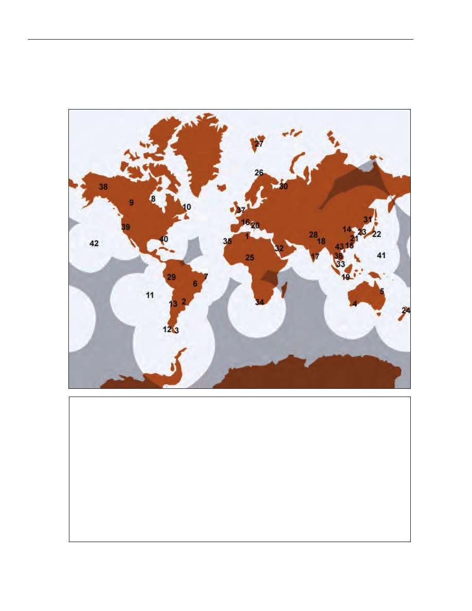
20
■ Chapter 1
■
Volume 5
Areas of Coverage for the Cospas-Sarsat Low-altitude Earth
Orbit System for Search and Rescue (LEOSAR)
1
Ouargla, Algeria
15
Hong Kong, China
29
Callao, Peru
2
Parana, Argentina
16
Toulouse, France
30
Arkhangelsk, Russia
3
Rio Grande, Argentina
17
Bangalore, India
31
Nakhodka, Russia
4
Albany, Australia
18
Lucknow, India
32
Jeddah, Saudi Arabia
5
Bundaberg, Australia
19
Jakarta, Indonesia
33
Singpore
6
Brasilia, Brazil
20
Bari, Italy
34
Cape Town, South Africa
7
Recife, Brazil
21
Keelung, ITDC
35
Maspalomas, Spain
8
Churchill, Canada
22
Yokohama, Japan
36
Bangkok, Thailand
9
Edmonton, Canada
23
Daejeon, Korea
37
Combe Martin, UK
10
Goose Bay, Canada
24
Wellington, New Zealand
38
Alaska, USA
11
Easter Island, Chile
25
Abuja, Nigeria
39
California, USA
12
Punta Arenas, Chile
26
Tromose, Norway
40
Florida, USA
13
Santiago, Chile
27
Spitsbergen, Norway
41
Guam
14
Beijing, China
28
Lahore, Pakistan
42
Hawaii, USA
43
Haiphong, Vietnam

virtually complete coverage of the approaches and
coastal waters of the United States, Guam, Northern
Marianas Islands, Puerto Rico, and the U.S. Virgin Is-
lands.
(344)
Urgent and safety radiotelephone broadcasts of
important Notice to Mariners items, storm warnings,
and other vital marine information are transmitted
upon receipt, and urgent broadcasts are repeated 15
minutes later; additional broadcasts are made at the
discretion of the originator. Urgent broadcasts are pre-
ceded by the urgent signal PAN-PAN (PAHN-PAHN,
spoken three times). Both the urgent signal and mes-
sage are transmitted on 2182 kHz and/or VHF-FM
channel 16, or 2670 kHz and/or channel 22A depend-
ing on broadcast length after an announcement on
2182 kHz and/or channel 16. Safety broadcasts are
preceded
by
the
safety
signal
SECURITY
(SAY-CURITAY, spoken three times). The Safety signal
is given on 2182 kHz and/or VHF-FM channel 16, and
the message is given on 2670 kHz and/or VHF-FM
channel 22A.
(345)
Scheduled radiotelephone broadcasts include rou-
tine weather, small-craft advisories, storm warnings,
navigational
information,
and
other
advisories.
Short-range broadcasts are made on 2670 kHz and/or
VHF-FM channel 22A, following a preliminary call on
2182 kHz and/or VHF-FM channel 16.
(346)
Weather information is not normally broadcast by
the Coast Guard on VHF-FM channel 22A in areas
where NOAA Weather Radio service is available. See
note below regarding VHF-FM channel 22A.
(347)
HF single-sideband voice broadcasts of high seas
weather information is available on the (carrier) fre-
quencies 4428, 6501, 8764, 13089, and 17314 kHz from
Portsmouth, VA.
(348)
Narrow-band direct printing (radio telex or sitor)
broadcasts of NAVAREA, weather, and other naviga-
tional warnings are transmitted on the following as-
signed frequencies:
(349)
6314, 8416.5, 12759, and 16806.5 kHz.
(350)
HF radiofacsimile broadcasts of weather and ice
charts are made on the following frequencies:
(351)
4235, 6340.5, 9110, and 12750 kHz.
National Standard Abbreviations for Broadcasts
(352)
A listing of Standard Abbreviations for Textual Mar-
itime Safety Broadcasts is contained in Appendix B.
These abbreviations were jointly approved by the U.S.
Coast Guard, National Weather Service, National
Geospatial-Intelligence Agency, and the Radio Techni-
cal Commission for Maritime Services. In addition to
appearing in radio broadcasts of the U.S. Coast Guard
and National Weather Service, they appear in Notices
to Mariners of the U.S. Coast Guard and National
Geospatial-Intelligence Agency, and in NAVTEX.
Coast Guard VHF-FM Channel 22A Broadcast
Warnings
(353)
The Coast Guard broadcasts urgent and routine
maritime safety information to ships on channel 22A
(157.10 MHz), the ship station transmit frequency por-
tion of channel 22, of Appendix 18 of the International
Telecommunications Union (ITU) Radio Regulations.
This simplex use of channel 22A is not compatible with
the international duplex arrangement of the channel
(coast transmit 161.70 MHz, ship transmit 157.10
MHz). As a result, many foreign flag vessels having ra-
dios tuned to the international channel 22 can not re-
ceive these maritime safety broadcasts.
(354)
Operators of vessels which transit U.S. waters and
who do not have VHF-FM radios tunable to USA chan-
nel 22A are urged to either obtain the necessary equip-
ment, to monitor the radiotelephone frequency 2182
kHz and tune to 2670 kHz when a broadcast is an-
nounced, or to carry a NAVTEX receiver.
NAVTEX Marine Information Broadcasts
(355)
NAVTEX is a maritime radio warning system con-
sisting of a series of coast stations transmitting radio
teletype (CCIR Recommendation 476 standard narrow
band direct printing, sometimes called Sitor or
ARQ/FEC) safety messages on the international stan-
dard medium frequency 518 kHz. Coast stations trans-
mit during preset time slots so as to minimize
interference with one another. Routine messages are
normally broadcast four to six times daily. Urgent mes-
sages are broadcast upon receipt, provided that an adja-
cent station is not transmitting. Since the broadcast
uses the medium frequency band, a typical station ser-
vice radius ranges to 200 NM.
(356)
Each NAVTEX message broadcast contains a
four-character header describing identification of sta-
tion (first character), message content (second charac-
ter), and message serial number (third and fourth
characters). This header allows the microprocessor in
the shipborne receiver to screen messages, selecting
only those stations relevant to the user, messages of
subject categories needed by the user, and messages
not previously received by the user. Selected messages
are printed on a roll of paper as received or stored, to be
read by the mariner at his convenience. Unwanted mes-
sages are suppressed. Certain categories of NAVTEX
messages cannot be suppressed by international agree-
ment. Suppression of unwanted messages is more and
more important to the mariner as the number of mes-
sages, including rebroadcasts, increases yearly.
General Information
■
Chapter 1
■
21
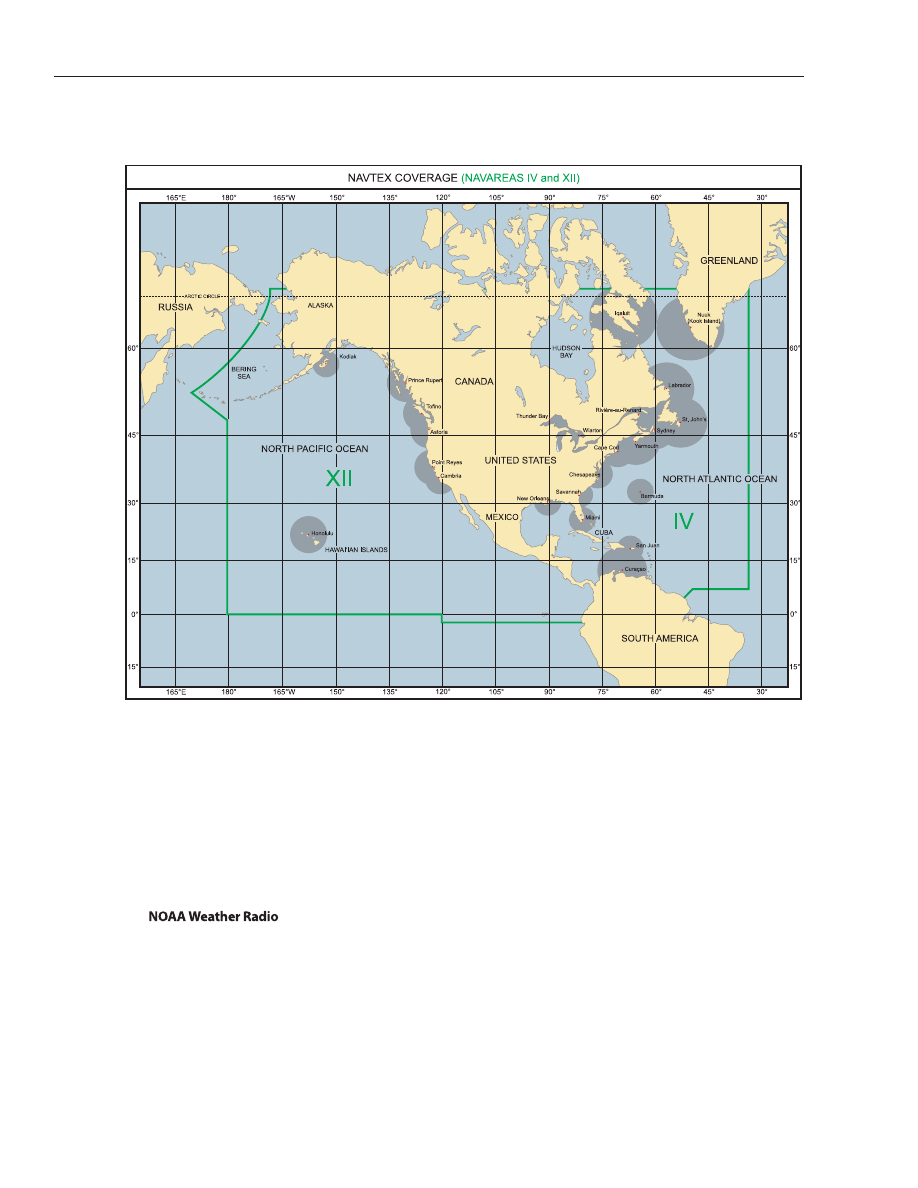
(357)
Vessels regulated by the Safety of Life at Sea
(SOLAS) Convention, as amended (cargo vessels over
300 tons and passenger vessels, on international voy-
ages), and operating in areas where NAVTEX service is
available, have been required to carry NAVTEX receiv-
ers since 1 August 1993. The USCG voice broadcasts
(Ch. 22A), often of more inshore and harbor informa-
tion, will remain unaffected by NAVTEX.
(358)
NOAA Weather Radio provides continuous broad-
casts of the latest weather information directly from
NWS offices. In addition to general weather informa-
tion, marine weather is provided by stations along the
sea coasts and the Great Lakes. During severe weather,
NWS forecasters can interrupt the regular broadcasts
and substitute special warning messages. The forecast-
ers can also activate specially designed warning receiv-
ers. These receivers either sound an alarm alerting the
listener to the forthcoming broadcast or, when
operated in a muted mode, automatically turn on so
that the warning message is heard.
(359)
NOAA Weather Radio taped messages are repeated
every 4 to 6 minutes and are routinely revised every 1 to
3 hours, or more frequently if necessary. The stations
operate 24 hours daily. The broadcasts are made on
seven VHF-FM frequencies, 162.40, to 162.55 MHz.
The 162.475 MHz frequency is only used in special
cases where needed to avoid channel interference. A
number of manufacturers offer special weather radios
to operate on these frequencies, with or without emer-
gency warning alarm, and many AM/FM radios on the
market now offer the “weather band” as an added fea-
ture. The broadcasts can usually be heard as far as 40
miles from the antenna site, sometimes more. The ef-
fective range depends on many factors, including the
height of the broadcast antenna, terrain, quality of the
receiver, and the type of receiving antenna. As a general
rule, listeners close to or perhaps beyond the 40 mile
range should have a good quality receiver system to get
22
■ Chapter 1
■
Volume 5

reliable reception. (See Appendix A for a list of these
stations in the area covered by this Coast Pilot.)
Marine Weather Services Charts (MSC)
(360)
Marine Weather Services Charts (MSC), published
by the National Weather Service, list frequencies and
schedules of broadcasts of stations giving weather fore-
casts and warnings. The charts are available from FAA,
National Aeronautical Navigation Services. (See Ap-
pendix A for address.)
Commercial radiotelephone coast stations
(361)
Broadcasts of coastal weather and warnings are
made by some commercial radiotelephone coast sta-
tions (marine operators) on the normal transmitting
frequencies of the stations. Vessels with suitable receiv-
ers and desiring this service may determine the fre-
quencies and schedules of these broadcasts from their
local stations, from Selected Worldwide Marine
Weather Broadcasts, or from the series of Marine
Weather Services Charts published by NWS.
Local broadcast-band radio stations
(362)
Many local radio stations in the standard AM and
FM broadcast band give local marine weather forecasts
from NWS on a regular schedule. These stations are
listed on the series of Marine Weather Services Charts
published by NWS.
Reports from ships
(363)
The master of every U.S. ship equipped with radio
transmitting apparatus, on meeting with a tropical cy-
clone, dangerous ice, subfreezing air temperatures
with gale force winds causing severe ice accretion on
superstructures, derelict, or any other direct danger to
navigation, is required to cause to be transmitted a re-
port of these dangers to ships in the vicinity and to the
appropriate Government agencies.
(364)
During the West Indies hurricane season, June 1 to
November 30, ships in the Gulf of Mexico, Caribbean
Sea area, southern North Atlantic Ocean, and the Pa-
cific waters west of Central America and Mexico are
urged to cooperate with NWS in furnishing these spe-
cial reports in order that warnings to shipping and
coastal areas may be issued.
Time Signals
(365)
The National Institute of Standards and Technol-
ogy (NIST) broadcasts time signals continuously, day
and night, from its radio stations WWV, near Fort Col-
lins, Colorado, (40°49'49"N., 105°02'27"W.) on fre-
quencies of 2.5, 5, 10, 15, and 20 MHz, and WWVH,
Kekaha, Kauai, Hawaii (21°59'26"N., 159°46'00"W.) on
frequencies 2.5, 5, 10, and 15 MHz. Services include
time announcements, standard time intervals, stan-
dard audio frequencies, geophysical alerts, BCD (binary
coded decimal) time code, UT1 time corrections, and
high seas storm information.
(366)
Time announcements are made every minute,
commencing at 15 seconds before the minute by a fe-
male voice and at 7½ seconds before the minute by a
male voice, from WWVH and WWV, respectively. The
time given is in Coordinated Universal Time (UTC) and
referred to the time at Greenwich, England, i.e., Green-
wich Mean Time.
(367)
NIST Time and Frequency Dissemination Ser-
vices, Special Publication 432, gives a detailed descrip-
tion of the time and frequency dissemination services of
the National Institute of Standards and Technology.
Single copies may be obtained upon request from the
National Institute of Standards and Technology, Time
and Frequency Division, Boulder, CO 80303. Quantities
may be obtained from the Government Printing Office
(see Appendix A for address).
CAUTIONARY INFORMATION
Destructive Waves
(368)
Unusual sudden changes in water level can be
caused by tsunamis or violent storms. These two types
of destructive waves have become commonly known as
tidal waves, a name which is technically incorrect as
they are not the result of tide-producing forces.
(369)
Tsunamis (seismic sea waves) are caused by sea-
bottom earthquakes. Many such seismic disturbances
do not produce sea waves and others produce small sea
waves, but the occasional large waves can be very dam-
aging to shore installations and dangerous to ships in
harbors.
(370)
These waves travel great distances and can cause
tremendous damage on coasts far from their source.
The wave of April 1, 1946, which originated in the Aleu-
tian Trench, demolished nearby Scotch Cap Light-
house and caused damages of 25 million dollars in the
Hawaiian Islands 2,000 miles away. The wave of May
22-23, 1960, which originated off Southern Chile,
caused widespread death and destruction in islands and
countries throughout the Pacific. A more recent tsu-
nami, the result of a December 26, 2004 earthquake off
the island of Sumatra, Indonesia, caused widespread
damage throughout the Indian Ocean. Damage was
heavy as far away as the east coast of Africa. It caused
over 200,000 deaths (as far away as South Africa) and 13
billion dollars worth of damage.
(371)
The speed of tsunamis varies with the depth of the
water, reaching 300 to 500 knots in the deep water of
the open ocean. In the open sea they cannot be detected
General Information
■
Chapter 1
■
23

from a ship or from the air because their length is so
great, sometimes a hundred miles, as compared to
their height, which is usually only a few feet (a meter or
2). The waves only build to disastrous proportions
when they approach shore.
(372)
There are usually a series of waves with crests 10 to
40 minutes apart, and the highest may occur several
hours after the first wave. Sometimes the first notice-
able part of the wave is the trough which causes a reces-
sion of the water from shore, and people who have gone
out to investigate this unusual exposure of the beach
have been engulfed by the oncoming crest. Such an un-
explained withdrawal of the sea should be considered as
nature’s warning of an approaching wave.
(373)
Improvements have been made in the quick deter-
mination and reporting of earthquake epicenters, but
no method has yet been perfected for determining
whether a sea wave will result from a given earthquake.
NOAA’s Pacific Tsunami Warning Center in Hawaii has
deployed a warning system which has field reporting
stations (seismic and tidal) in most countries around
the Pacific. When a warning is broadcast, waterfront
areas should be vacated for higher ground, and ships in
the vicinity of land should head for the deep water of
the open sea.
Storm surge
(374)
A considerable rise or fall in the level of the sea
along a particular coast may result from strong winds
and sharp change in barometric pressure. In cases
where the water level is raised, higher waves can form
with greater depth and the combination can be de-
structive to low regions, particularly at high stages of
tide. Extreme low levels can result in depths which are
considerably less than those shown on nautical charts.
This type of wave occurs especially in coastal regions
bordering on shallow waters which are subject to tropi-
cal storms.
(375)
Seiche is a stationary vertical wave oscillation with
a period varying from a few minutes to an hour or
more, but somewhat less than the tidal periods. It is
usually attributed to external forces such as strong
winds, changes in barometric pressure, swells, or tsu-
namis disturbing the equilibrium of the water surface.
Seiche is found both in enclosed bodies of water and su-
perimposed upon the tides of the open ocean. When the
external forces cause a short-period horizontal oscilla-
tion on the water, it is called surge.
(376)
The combined effect of seiche and surge sometimes
makes it difficult to maintain a ship in its position
alongside a pier even though the water may appear to
be completely undisturbed, and heavy mooring lines
have been parted repeatedly under such conditions. Pi-
lots advise taut lines to reduce the effect of the surge.
Immersion Hypothermia
(377)
Immersion hypothermia is the loss of heat when a
body is immersed in water. With few exceptions, hu-
mans die if their core temperature of approximately
99.7° F drops below 78.6° F. Cardiac arrest is the most
common direct cause of death. During prolonged im-
mersion, the main threat to life is cold or cold and
drowning combined.
(378)
The length of time that a human survives in water
depends on the water temperature, and to a lesser ex-
tent, on the person’s behavior and body type. The table
below shows approximate human survival time in the
sea. Body type can cause deviations, as small people be-
come hypothermic more rapidly than large people. The
cooling rate can be slowed by the person’s behavior and
insulated gear. The Heat Escape Lessening Posture
(HELP) was developed for those in the water alone and
the Huddle for small groups. Both require a PFD (per-
sonal flotation device), or life preserver. HELP involves
holding the arms close to the body, keeping the thighs
together, and raising the knees to protect the groin
area. In the Huddle, people face each other and keep
their bodies as close together as possible. These posi-
tions improve survival time to approximately two times
that of a swimmer and one and a half times that of a
person in the passive position.
(379)
Near-drowning victims in cold water (less than 70°
F) are revivable for much longer periods than usual.
Keys to a successful revival are immediate cardiopul-
monary resuscitation (CPR) and administration of pure
oxygen. Total re-warming is not necessary at first. The
whole revival process may take hours and require med-
ical help.
Survival Time Versus Water Temperature
Water Tempera-
ture
Exhaustion or
Unconsciousness
Expected Time of
Survival
32°F
15 min.
15–45 min.
32°–41°F
15–30 min.
30–90 min.
41°–50°F
30–60 min.
1–3 hrs.
50°–59°F
1–2 hrs.
1–6 hrs.
59°–68°F
2–7 hrs.
2–40 hrs.
68°–77°F
3–12 hrs.
3 hrs–indef.
77°F and above
indefinite
indefinite
Wind Chill and Frostbite
(380)
When the body is warmer than its surroundings, it
begins to lose heat. The rate of loss depends on barriers
such as clothing and insulation, the speed of air move-
ment and air temperature. Heat loss increases dramati-
cally in moving air that is colder than skin temperature
(91.4° F). Even a light wind increases heat loss, and a
24
■ Chapter 1
■
Volume 5

strong wind can lower the body temperature if the rate
of loss is greater than the body’s heat replacement rate.
(381)
When skin temperature drops below 50° F, there is
a marked constriction of blood vessels, leading to vas-
cular stagnation, oxygen want and cellular damage.
The first indication that something is wrong is a pain-
ful tingling. Swelling of varying extent follows, pro-
vided freezing has not occurred. Excruciating pain may
be felt if the skin temperature is lowered rapidly, but
freezing of localized portions of the skin may be pain-
less when the rate of change is slow. Possible effects of
cold include cold allergy (welts), chilblains, which ap-
pear as reddened, warm, itching, swollen patches on
the fingers and toes, and trench foot and immersion
foot, which present essentially the same picture. Both
result from exposure to cold and lack of circulation.
Wetness can add to the problem as water and wind
soften the tissues and accelerate heat loss.
(382)
Frostbite usually begins when the skin tempera-
ture falls within the range of 14° to 4° F. Ice crystals
form in the tissues and small blood vessels. The rate of
heat loss determines the rate of freezing, which is ac-
celerated by wind, wetness, extreme cold and poor
blood circulation. Parts of the body susceptible to
freezing are those with surfaces large in relation to
their volume, such as toes, fingers, ears, nose, chin and
cheeks.
(383)
Injuries from the cold may, to a large extent, be
prevented by maintaining natural warmth through the
use of proper footgear and adequate, dry clothing, by
avoiding cramped positions and constricting clothing
and by active exercise of the hands, legs and feet.
MARINE POLLUTION
The Federal Water Pollution Control Act or Clean
Water Act
(384)
The Federal Water Pollution Control Act (FWPCA)
or Clean Water Act (CWA) was passed to restore and
maintain the chemical, physical and biological integ-
rity of our nation’s waters.
No-Discharge Zones
(385)
Section 312 of the FWPCA gives the Environmental
Protection Agency (EPA) and States the authority to
designate certain areas as No-Discharge Zones (NDZ)
for vessel sewage. Freshwater lakes, freshwater reser-
voirs, or other freshwater impoundments whose en-
trances and exits prohibit traffic by regulated vessels
(vessels with installed toilets) are, by regulation, NDZs.
Rivers that do not support interstate navigation vessel
traffic are also NDZs by regulation. Water bodies that
can be designated as NDZs by States and EPA include:
the Great Lakes and their connecting waterways, fresh-
water lakes and impoundments accessible through
locks, and other flowing waters that support interstate
navigation by vessels subject to regulation.
(386)
Inside No-Discharge Zone waters, discharge of any
sewage, whether treated or untreated, is completely
prohibited.
(387)
Discharge of sewage in waters not designated as
No-Discharge Zones is regulated by the Marine Sanita-
tion Device Standard (see 40 CFR 140 in Chapter 2.)
(388)
(Additional information concerning the regula-
tions may be obtained from the Environmental Protec-
tion Agency (EPA) website: http://www.epa.gov/owow/
oceans/regulatory/vessel_sewage/.)
Oil Pollution
(389)
The FWPCA also prohibits the discharge of quanti-
ties of either oil or hazardous substance which may be
harmful into or upon the navigable waters of the
United States. This prohibition also applies to adjoin-
ing shorelines, waters of the contiguous zone, activi-
ties connected with the Outer Continental Shelf Lands
Act (OSLA) and Deepwater Port Act of 1974, and such
discharges which may affect natural resources belong-
ing to the United States or under its exclusive manage-
ment authority, including those resources under the
Fishery Conservation and Management Act of 1976. In
the event a spill does occur in violation of the Act the
person in charge of a vessel or onshore or offshore facil-
ity is required to notify the Coast Guard as soon as he
has knowledge of the spill. Such notification is to be by
the most rapid means available to the National Re-
sponse Center (1-800-424-8802, nationwide 24 hour
number).
The Act to Prevent Pollution from Ships
(390)
The Act to Prevent Pollution from Ships (33 U.S.C.
1901) implements into U.S. law the International Con-
vention for the Prevention of Pollution from Ships, as
modified by the Protocol of 1978 (MARPOL 73/78). An-
nex I of MARPOL 73/78 deals with oil and oily waste,
Annex II with hazardous chemicals and other sub-
stances referred to as Noxious Liquid Substances
(NLS), and Annex V deals with the prevention of marine
pollution by plastics and other garbage produced dur-
ing vessel operations.
(391)
Annex I of MARPOL 73/78 is applicable to oceango-
ing tankers over 150 gross tons and all other oceango-
ing ships over 400 gross tons. The MARPOL 73/78
requirements include oily waste discharge limitations,
oily-water separating equipment, monitoring and
alarm systems for discharges from cargo areas, cargo
pump rooms and machinery space bilges. Ships to
which Annex I MARPOL 73/78 is applicable are also
General Information
■
Chapter 1
■
25

26
■ Chapter 1
■
Volume 5
required to have an International Oil Pollution Preven-
tion (IOPP) Certificate verifying that the vessel is in
compliance with the requirements of MARPOL 73/78
and that any required equipment is on board and opera-
tional. Vessels must also maintain an Oil Record Book
recording all oil transfers and discharges. The Oil Re-
cord Book is available from USCG Supply Center Balti-
more or any local Captain of the Port.
(392)
Annex II of MARPOL 73/78 is applicable to ocean-
going vessels and non-self propelled oceangoing ships
which carry Noxious Liquid Substances (NLS) in bulk.
The Annex II requirements include discharge restric-
tions for various classes of cargo residues; the mainte-
nance of a Cargo Record Book for recording all NLS
cargo and residue transfers and discharges; and a Pro-
cedures and Arrangements Manual describing the cor-
rect procedures for off loading and prewashing cargo
tanks.
(393)
Annex II NLS cargoes are classified in one of four
categories, A, B, C, or D. Category A is the most hazard-
ous to the environment. Category A and other sub-
stances which tend to solidify in tanks must be
prewashed in port under the supervision of a Prewash
Surveyor prior to departure from the off loading termi-
nal. Vessel discharges must be underwater when dis-
charge at sea is allowed. Tanks which carry Category B
and C NLS must be tested to ensure that after tank
stripping only a minimal amount of residues will re-
main. Reception facilities must be able to assist in
cargo stripping operations by reducing back pressure
during the final stages of off loading.
(394)
Terminals and ports receiving oceangoing tankers,
or any other oceangoing ships of 400 GT or more, car-
rying residues and mixtures containing oil, or receiv-
ing oceangoing ships carrying NLSs, are required to
provide adequate reception facilities for the wastes
generated. Coast Guard Captains of the Port issue a
Certificate of Adequacy to terminals or ports to show
that they are in compliance with federal reception facil-
ity requirements. An oceangoing tanker or any other
oceangoing ship of 400 GT or more required to retain
oil or oily residues and mixtures on board and an
oceangoing ship carrying a Category A, B or C NLS
cargo or NLS residue in cargo tanks that are required
to be prewashed, may not enter any port or terminal
unless the port or terminal holds a valid Certificate of
Adequacy or unless the ship is entering under force
majeure.
(395)
Annex V is applicable to all recreational, fishing,
uninspected and inspected vessels, and foreign flag ves-
sels on the navigable waters and all other waters sub-
ject to the jurisdiction of the United States, out to and
including the Exclusive Economic Zone (200 miles).
(396)
Annex V prohibits the disposal of any and all plastic
material from any vessel anywhere in the marine envi-
ronment. Dunnage, lining and packing materials
which float may be disposed of beyond 25 miles from
the nearest land. Other garbage that will not float may
be disposed of beyond 12 miles of land, except that gar-
bage which can pass through a 25mm mesh screen (ap-
proximately 1 square inch) may be disposed of beyond 3
miles. Dishwater is not to be considered garbage within
the meaning of Annex V when it is the liquid residue
from the manual or automatic washing of dishes or
cooking utensils. More restrictive disposal regimes ap-
ply in waters designated “Special Areas.” This Annex re-
quires terminals to provide reception facilities at ports
and terminals to receive plastics and other garbage
from visiting vessels.
(397)
The civil penalty for each violation of MARPOL
73/78 is not more than $25,000. The criminal penalty
for a person who knowingly violates the MARPOL Pro-
tocol, or the regulations (33 CFR 151, 155, 157, and
158), consists of a fine of not more than $250,000
and/or imprisonment for not more than 5 years; U.S.
law also provides criminal penalties up to $500,000
against organizations which violate MARPOL.
Packaged Marine Pollutants
(398)
On October 1, 1993, new regulations under the
Hazardous Materials Transportation Act (HMTA) took
effect, implementing MARPOL Annex III in the United
States. MARPOL Annex III deals with the prevention of
marine pollution by harmful substances in packaged
form.
(399)
Annex III of MARPOL 73/78 applies to all ships car-
rying harmful substances in packaged form. Annex III
provides standards for stowage, packing, labeling,
marking, and documentation of substances identified
as marine pollutants in the International Maritime
Dangerous Goods Code (IMDG Code). On 5 November
1992, the U.S. Research and Special Programs Admin-
istration (RSPA) amended the Hazardous Materials
Regulations (HMR, 49 CFR 100-177) to list and regu-
late these marine pollutants in all modes of transporta-
tion.
(400)
Marine pollutants are divided into two classes: ma-
rine pollutants and severe marine pollutants. A solu-
tion or mixture containing 10% or more of any marine
pollutant falls into the class of “marine pollutant.” The
“severe marine pollutant” class consists of those mate-
rials that contain 1% or more of any specified “severe
marine pollutant” substance. Marine pollutants that do
not meet the criteria for any other hazard class are
transported as an environmentally hazardous sub-
stance.

Ocean Dumping
(401)
The Marine Protection Research and Sanctuaries
Act of 1972, as amended (33 USC 1401 et seq.), regu-
lates the dumping of all material, except fish waste,
into ocean waters. Radiological, chemical and biologi-
cal warfare agents and other high level radioactive
wastes are expressly banned from ocean disposal. The
U.S. Army Corps of Engineers issues permits for the
disposal of dredged spoils; the Environmental Protec-
tion Agency is authorized to issue permits for all other
dumping activities. Surveillance and enforcement to
prevent unlawful transportation of material for dump-
ing or unlawful dumping under the Act has been as-
signed to the U.S. Coast Guard. The Act provides civil
penalties of up to $50,000 and criminal penalties of up
to $50,000 and/or one year imprisonment.
MINECLEARING: CAUTION
Keep Clear of Mineclearance Vessels (COLREGS
1972)
(402)
(a) United States vessels engaged in mineclearing
operations or exercises are hampered to a considerable
extent in their maneuvering powers.
(403)
(b) With a view to indicating the nature of the work
on which they are engaged, these vessels will show the
signals hereinafter mentioned. For the public safety, all
other vessels, whether steamers or sailing craft, must
endeavor to keep out of the way of vessels displaying
these signals and not approach them inside the dis-
tances mentioned herein, especially remembering that
it is dangerous to pass between the vessels of a pair or
group sweeping together.
(404)
(c) All vessels towing sweeps are to show:
(405)
BY DAY–A black ball at the fore mast and a black
ball at the end of each fore yard.
(406)
BY NIGHT–All around green lights instead of the
black balls, and in a similar manner.
(407)
(d) Vessels or formations showing these signals are
not to be approached nearer than 1,000 meters. Under
no circumstances is a vessel to pass through a forma-
tion of minesweepers.
(408)
(e) Mineclearance vessels should be prepared to
warn merchant vessels which persist in approaching
too close by means of any of the appropriate signals
from the International Code of Signals.
(409)
(f) In fog, mist, falling snow, heavy rainstorms, or
any other conditions similarly restricting visibility,
whether by day or night, mineclearance vessels while
towing sweeps when in the vicinity of other vessels will
sound signals for a vessel towing (1 prolonged blast fol-
lowed by 2 short blasts).
Helicopters Conducting Mineclearance Operations
(410)
(g) The United States is increasingly employing he-
licopters to conduct mineclearance operations or exer-
cises. When so engaged, helicopters, like vessels, are
considerably hampered in their ability to maneuver.
Accordingly, surface craft approaching helicopters en-
gaged in mineclearance operations should take safety
precautions similar to those described in (b) and (d)
above with respect to mineclearance vessels.
(411)
(h) Helicopters towing mineclearance gear and ac-
companying surface escorts, if any, will use all available
means to warn approaching ships of the operations or
exercises being conducted. Also, measures will be
taken where practicable to mark or light the gear or ob-
jects being towed.
(412)
(i) Mineclearance helicopters are equipped with a
rotating beacon which has selectable red and amber
modes. The amber mode is used during towing opera-
tions to notify/warn other vessels that the helicopter is
towing. While towing, the helicopter’s altitude varies
from 15 to 95 meters above the water and speeds vary
from 0 to 30 knots.
(413)
(j) General descriptions and approximate dimen-
sions for towed mineclearance gear currently being
used in conjunction with helicopters are as follows:
(414)
(1) Mechanical sweep gear consisting, in part, of
large lengths of submerged cables and explosive cut-
ters. The only items normally visible on the surface are
three to five international orange floats, depending
upon the quantity of gear in use, which generally define
the dimensions of the tow. The maximum width is 100
meters and the maximum distance behind the helicop-
ter is 600 meters.
(415)
(2) Acoustical sweep device weighing approxi-
mately 70 pounds (32 kg). This device is towed behind
the helicopter on a 250-meter orange polypropylene
tow cable. When dead in the water, the gear will rise to
the surface, supported by a yellow float.
(416)
(3) A hydrofoil platform containing equipment
used for magnetic influence sweeping. The platform is
towed on the end of a 140-meter cable and trails elec-
trodes in the water which extend 185 meters behind
the platform. Very often, the aforementioned acousti-
cal sweep device is towed in conjunction with this plat-
form by attaching it to the end of one of the electrodes
by a 30-meter polypropylene tow line. In this configu-
ration, the total length of the tow is 215 and 350 me-
ters, respectively, behind the hydrofoil platform and
helicopter. Special care must be exercised when cross-
ing astern of the hydrofoil platform as the towed cable
is barely visible, and the attached acoustic device is
submerged just beneath the surface and is not visible to
surface vessels.
General Information
■
Chapter 1
■
27

(417)
(k) Helicopters employed in mineclearance opera-
tions and their tows may function at night as well as
day, and in various types of weather conditions. The
major danger to any surface vessel is getting the various
cables wrapped in its screws. Small craft also are subject
to the risk of collision with the hydrofoil platform.
Submarine Emergency Identification Signals and
Hazard to Submarines
(418)
U.S. submarines are equipped with signal ejectors
which may be used to launch identification signals, in-
cluding emergency signals. Two general types of sig-
nals may be used: smoke floats and flares or stars. A
combination signal which contains both smoke and
flare of the same color may also be used. The smoke
floats, which burn on the surface, produce a dense, col-
ored smoke for a period of fifteen to forty-five seconds.
The flares or stars are propelled to a height of three
hundred to four hundred feet (90 to 120 meters) from
which they descend by small parachute. The flares or
stars burn for about twenty-five seconds. The color of
the smoke or flare/star has the following meaning:
(419)
(a) GREEN OR BLACK–Used under training exer-
cise conditions only to indicate that a torpedo has been
fired or that the firing of a torpedo has been simulated.
(420)
(b) YELLOW–Indicates that submarine is about to
come to periscope depth from below periscope depth.
Surface craft terminate antisubmarine counter-attack
and clear vicinity of submarine. Do not stop propellers.
(421)
(c) RED–Indicates an emergency condition within
the submarine and that it will surface immediately, if
possible. Surface ships clear the area and stand by to
give assistance after the submarine has surfaced. In
case of repeated red signals, or if the submarine fails to
surface within reasonable time, she may be assumed to
be disabled. Buoy the location, look for submarine buoy
and attempt to establish sonar communications. Ad-
vise U.S. Naval authorities immediately.
(422)
(d) WHITE–Two white flares/smoke in succession
indicates that the submarine is about to surface, usu-
ally from periscope depth (non-emergency surfacing
procedure). Surface craft should clear the vicinity of
the submarine.
(423)
A Submarine Marker Buoy consists of a cylindri-
cally shaped object about 3 feet by 6 feet with connect-
ing structure and is painted international orange. The
buoy is a messenger buoy with a wire cable to the sub-
marine; this cable acts as a downhaul line for a rescue
chamber. The buoy may be accompanied by an oil slick
release to attract attention. A submarine on the bottom
in distress and unable to surface will, if possible, release
this buoy. If an object of this description is sighted, it
should be investigated and U.S. Naval Authorities ad-
vised immediately.
(424)
Transmission of the International Distress Signal
(SOS) will be made on the submarine’s sonar gear inde-
pendently or in conjunction with the red emergency
signal as conditions permit. Submarines may employ
any or all of the following additional means to attract
attention and indicate their position while submerged:
(425)
Release of dye marker.
(426)
Release of air bubble.
(427)
Ejection of oil.
(428)
Pounding on the hull.
(429)
United States destroyer-type vessels in interna-
tional waters will, on occasion, stream a towed under-
water object at various speeds engaged in naval
maneuvers. All nations operating submarines are ad-
vised that this underwater object in the streamed con-
dition constitutes a possible hazard to submerged
submarines.
Vessels Constrained by their Draft
(430)
International Navigation Rules, Rule 28, states that
a vessel constrained by her draft may, in addition to the
lights prescribed for power-driven vessels in Rule 23,
exhibit where they can best be seen three all-around
red lights in a vertical line, or a cylinder.
Special signals for surveying vessels
(431)
Vessels engaged in survey operations and limited in
their ability to maneuver because of the work being
performed (handling equipment over-the-side such as
water sampling or conductivity-temperature-density
(CTD) casts, towed gear, bottom samplers, etc., and di-
vers working on, below or in proximity of the vessel)
are required by Navigation Rules, International-Inland,
Rule 27, to exhibit:
(432)
(b)(i) three all-round lights in a vertical line where
they can best be seen. The highest and lowest of these
lights shall be red and the middle light shall be white;
(433)
(ii) three shapes in a vertical line where they can
best be seen. The highest and lowest of these shapes
shall be balls and the middle one a diamond;
(434)
(iii) when making way through the water, mast-
head lights, sidelights and a sternlight, in addition to
the lights prescribed in subparagraph (b)(i); and
(435)
(iv) when at anchor, in addition to the lights or
shapes prescribed in subparagraphs (b)(i) and (ii) the
light, lights or shapes prescribed in Rule 30, Anchored
Vessels and Vessels Aground.
(436)
A vessel engaged in hydrographic survey opera-
tions (making way on a specific trackline while sound-
ing the bottom) is not restricted in its ability to
maneuver and therefore exhibits at night only those
lights required for a power-driven vessel of its length.
28
■ Chapter 1
■
Volume 5

General Information
■
Chapter 1
■
29
(437)
Warning signals for Coast Guard vessels while
handling or servicing aids to navigation are the same
as those prescribed for surveying vessels.
VHF-FM Radiotelephone
(438)
VHF-FM channel 16 (156.800 MHz) is the interna-
tional distress, urgency, safety, calling and reply fre-
quency for vessels and public and private coastal
stations. In 1992, the Federal Communications Com-
mission (FCC) designated VHF-FM channel 9 (156.450
MHz) for use as a general purpose calling frequency for
non-commercial vessels, such as recreational boats.
This move was designed to relieve congestion on
VHF-FM channel 16. Non-commercial vessels are en-
couraged to use VHF-FM channel 9, for routine com-
munications but distress, urgency, and safety calls
should continue to be initially made on VHF-FM chan-
nel 16. U.S. Coast Guard stations do not guard VHF-FM
channel 9.
(439)
The following table provides the frequency equiva-
lents and general usage of selected VHF-FM channels
which appear in the Coast Pilot. The letter “A” ap-
pended to a channel number indicates that U.S. opera-
tion of the particular channel is different than the
international operation, i.e., U.S. stations transmit and
receive on the same frequency and international sta-
tions use different frequencies.
(440)
All channels given in the table (later in this chap-
ter) are designated for both ship-to-ship and ship-to-
coast communications except as noted.
SELECT NAVIGATION RULES
Improper use of searchlights
(441)
No person shall flash or cause to be flashed the rays
of a searchlight or other blinding light onto the bridge
or into the pilothouse of any vessel underway. The In-
ternational Code Signal “PG2” may be made by a vessel
inconvenienced by the glare of a searchlight in order to
apprise the offending vessel of the fact.
Use of Radar
(442)
Navigation Rules, International-Inland, Rule 7,
states, in part, that every vessel shall use all available
means appropriate to the prevailing circumstances and
conditions to determine if risk of collision exists. If
there is any doubt such risk shall be deemed to exist.
Proper use shall be made of radar equipment if fitted
and operational, including long-range scanning to ob-
tain early warning of risk of collision and radar plotting
or equivalent systematic observation of detected ob-
jects.
(443)
This rule places an additional responsibility on ves-
sels which are equipped and manned to use radar to do
so while underway during periods of reduced visibility
without in any way relieving commanding officers of
the responsibility of carrying out normal precaution-
ary measures.
(444)
Navigation Rules, International-Inland, Rules 6, 7,
8, and 19 apply to the use of radar.
Danger signal
(445)
Navigation Rules, International-Inland, Rule 34(d),
states that when vessels in sight of one another are ap-
proaching each other and from any cause either vessel
fails to understand the intentions or actions of the
other, or is in doubt whether sufficient action is being
taken by the other to avoid collision, the vessel in doubt
shall immediately indicate such doubt by giving at least
five short and rapid blasts on the whistle. Such signal
may be supplemented by a light signal of at least five
short and rapid flashes.
Narrow channels
(446)
Navigation Rules, International-Inland, Rule 9(b)
states: A vessel of less than 65.6 feet (20 meters) in
length or a sailing vessel shall not impede the passage
of a vessel that can safely navigate only within a narrow
channel or fairway.
Control of shipping in time of emergency or war
(447)
In time of war or national emergency, merchant
vessels of the United States and those foreign flag ves-
sels, which are considered under effective U.S. control,
will be subject to control by agencies of the U.S. Gov-
ernment. The allocation and employment of such ves-
sels, and of domestic port facilities, equipment, and
services will be performed by appropriate agencies of
the War Transport Administration. The movement,
routing, and diversion of merchant ships at sea will be
controlled by appropriate naval commanders. The
movement of merchant ships within domestic ports
and dispersal anchorages will be coordinated by the
U.S. Coast Guard. The commencement of naval control
will be signaled by a general emergency message. (See
NGA Pub. 117 for emergency procedures and commu-
nication instructions.)
Homeland Security Advisory System
(448)
The Homeland Security Advisory System is a com-
prehensive and effective means to disseminate infor-
mation regarding the risk of terrorist acts to Federal,
State, and local authorities and to the American people.
The system is designed to guide our protective mea-
sures when specific information to a particular sector

30
■ Chapter 1
■
Volume 5
Channel
Ship Frequency (MHz)
Channel Usage
Transmit
Receive
1A
156.050
156.050
Port Operations and commercial, VTS (Note 2)
5A
156.250
156.250
Port Operations or VTS (Note 1)
6
156.300
156.300
Intership safety
7A
156.350
156.350
Commercial
8
156.400
156.400
Commercial (Intership only)
9
156.450
156.450
Boater Calling; Commercial/Non-commercial
10
156.500
156.500
Commercial
11
156.550
156.550
Commercial; VTS in certain areas
12
156.600
156.600
Port Operations; VTS in certain areas
13
156.650
156.650
Intership Navigation (bridge-to-bridge) (Note 4)
14
156.700
156.700
Port Operations; VTS in certain areas
15
N/A
156.750
Environmental (receive only)
16
156.800
156.800
International Distress, Safety and Calling (Note 5)
17
156.850
156.850
State control
18A
156.900
156.900
Commercial
19A
156.950
156.950
Commercial
20
157.000
161.600
Port Operations (duplex)
20A
157.000
157.000
Port Operations
21A
157.050
157.050
U.S. Coast Guard
22A
157.100
157.100
Coast Guard Liaison/Maritime Safety Information Broadcasts (channel 16)
23A
157.150
157.150
U.S. Coast Guard
24
157.200
161.800
Public Correspondence (Marine Operator)
25
157.250
161.850
Public Correspondence (Marine Operator)
26
157.300
161.900
Public Correspondence (Marine Operator)
27
157.350
161.950
Public Correspondence (Marine Operator)
28
157.400
162.000
Public Correspondence (Marine Operator)
63A
156.175
156.175
Port Operations and Commercial, VTS (Note 2)
65A
156.275
156.275
Port Operations
66A
156.325
156.325
Port Operations
67
156.375
156.375
Commercial (Note 3)
68
156.425
156.425
Non-Commercial
69
156.475
156.475
Non-Commercial
70
156.525
156.525
Digital Selective Calling (voice communications not allowed)
71
156.575
156.575
Non-Commercial
72
156.625
156.625
Non-Commercial (Intership only)
73
156.675
156.675
Port Operations
74
156.725
156.725
Port Operations
77
156.875
156.875
Port Operations (Intership only)
78A
156.925
156.925
Non-Commercial
79A
156.975
156.975
Commercial (Non-commercial in Great Lakes only)
80A
157.025
157.025
Commercial (Non-commercial in Great Lakes only)
81A
157.075
157.075
U.S. Government (environmental protection operations)
82A
157.125
157.125
U.S. Government
83A
157.175
157.175
U.S. Coast Guard
84
157.225
161.825
Public Correspondence (Marine Operator)
85
157.275
161.875
Public Correspondence (Marine Operator)
86
157.325
161.925
Public Correspondence (Marine Operator)
87
157.375
161.375
Public Correspondence (Marine Operator)
88A
157.425
157.425
Commercial (Intership only)
AIS 1
161.975
161.975
Automatic Identifi cation System (AIS)
Note 1 – Houston, New Orleans and Seattle areas.
Note 2 – Available only in New Orleans/Lower Mississippi area.
Note 3 – Used for bridge-to-bridge communications in Lower Mississippi River. (Intership only.)
Note 4 – Ships greater than 20 meters in length maintain a listening watch on this channel in U.S. waters.
Note 5 – Ships required to carry radio, USCG, and most coast stations maintain a listening watch on this channel.

General Information
■
Chapter 1
■
31
or geographic region is received. It combines threat in-
formation with vulnerability assessments and provides
communications to public safety officials and the pub-
lic. This communication is achieved through threat ad-
visories, information bulletins, and a color-coded
threat level system.
U.S. Coast Guard Maritime Security (MARSEC)
Levels
(449)
The U.S. Coast Guard has a three-tiered system of
Maritime Security (MARSEC) Levels consistent with
the Department of Homeland Security's Homeland Se-
curity Advisory System (HSAS). MARSEC levels are de-
signed to provide a means to easily communicate
pre-planned scalable responses to increased threat lev-
els. The Commandant of the U.S. Coast Guard sets
MARSEC levels commensurate with the HSAS. Be-
cause of the unique nature of the maritime industry,
the HSAS threat conditions and MARSEC levels will
align closely, though they will not directly correlate.
(450)
MARSEC Level 1 – the level for which minimum
appropriate security measures shall be maintained at
all times. MARSEC 1 generally applies when HSAS
Threat Condition Green, Blue, or Yellow are set.
(451)
MARSEC Level 2 – the level for which appropriate
additional protective security measures shall be main-
tained for a period of time as a result of heightened risk
of a transportation security incident. MARSEC 2 gener-
ally corresponds to HSAS Threat Condition Orange.
(452)
MARSEC Level 3 – the level for which further spe-
cific protective security measures shall be maintained
for a limited period of time when a transportation secu-
rity incident is probable, imminent, or has occurred,
although it may not be possible to identify the specific
target. MARSEC 3 generally corresponds to HSAS
Threat Condition Red.
REGULATED WATERS
Traffic Separation Schemes (Traffic Lanes)
(453)
To increase the safety of navigation, particularly in
converging areas of high traffic density, routes incor-
porating traffic separation have been adopted by the
IMO in certain areas of the world. In the interest of safe
navigation, it is recommended that through traffic use
these schemes, as far as circumstances permit, by day
and by night and in all weather conditions.
(454)
An area to be avoided (ATBA) is a routing measure
comprising an area within defined limits, in which ei-
ther navigation is particularly hazardous or it is excep-
tionally important to avoid casualties, and which
should be avoided by all ships, or certain classes of
ships.
(455)
The International Maritime Organization (IMO) is
recognized as the only international body responsible
for establishing and recommending measures on an in-
ternational level concerning ships’ routing. In deciding
whether or not to adopt or amend a traffic separation
scheme, IMO will consider whether the scheme com-
plies with the design criteria for traffic separation
schemes and with the established methods of routing.
IMO also considers whether the aids to navigation pro-
posed will enable mariners to determine their position
with sufficient accuracy to navigate the scheme in ac-
cordance with Rule 10 of the International Regulations
for Preventing Collisions at Sea (72 COLREGS).
(456)
General principles for navigation in Traffic Separa-
tion Schemes are as follows:
(457)
1. A ship navigating in or near a traffic separation
scheme adopted by IMO shall in particular comply with
Rule 10 of the 72 COLREGS to minimize the develop-
ment of risk of collisions with another ship. The other
rules of the 72 COLREGS apply in all respects, and par-
ticularly the steering and sailing rules if risk of colli-
sion with another ship is deemed to exist.
(458)
2. Traffic separation schemes are intended for use
by day and by night in all weather, ice-free waters or un-
der light ice conditions where no extraordinary ma-
neuvers or assistance by icebreaker(s) is required.
SEVERE
HIGH
ELEVATED
GUARDED
LOW
SEVERE RISK OF
TERRORIST ATTACKS
HIGH RISK OF
TERRORIST ATTACKS
SIGNIFICANT RISK OF
TERRORIST ATTACKS
GENERAL RISK OF
TERRORIST ATTACKS
LOW RISK OF
TERRORIST ATTACKS

(459)
3. Traffic separation schemes are recommended for
use by all ships unless stated otherwise. Bearing in
mind the need for adequate underkeel clearance, a de-
cision to use a traffic separation scheme must take into
account the charted depth, the possibility of changes in
the seabed since the time of last survey, and the effects
of meteorological and tidal conditions on water depths.
(460)
4. A deep water route is an allied routing measure
primarily intended for use by ships which require the
use of such a route because of their draft in relation to
the available depth of water in the area concerned.
Through traffic to which the above consideration does
not apply should, if practicable, avoid following deep
water routes. When using a deep water route mariners
should be aware of possible changes in the indicated
depth of water due to meteorological or other effects.
(461)
5. The arrows printed on charts merely indicate the
general direction of traffic; ships should not set their
courses strictly along the arrows.
(462)
6. Vessels should, so far as practicable, keep clear of
a traffic separation line or separation zone.
(463)
7. Vessels should avoid anchoring in a traffic sepa-
ration scheme or in the area near its termination.
(464)
8. The signal “YG” meaning “You appear not to be
complying with the traffic separation scheme” is pro-
vided in the International Code of Signals for appropri-
ate use.
(465)
Note–Several governments administering Traffic
Separation Schemes have expressed their concern to
IMO about the large number of infringements of Rule
10 of the 72 COLREGS and the dangers of such contra-
ventions to personnel, vessels and environment. Sev-
eral governments have initiated surveillance of traffic
separation schemes for which they are responsible and
are providing documented reports of vessel violations
to flag states. As in the past, the U.S. Coast Guard will
investigate these reports and take appropriate action.
Mariners are urged to comply at all times with the 72
COLREGS.
(466)
9. Notice of temporary adjustments to traffic sepa-
ration schemes for emergencies or for accommodation
of activities which would otherwise contravene Rule 10
or obstruct navigation may be made in Notices to Mari-
ners. Temporary adjustments may be in the form of a
precautionary area within a traffic lane, or a shift in the
location of a lane.
(467)
10. The IMO approved routing measures which af-
fect shipping in or near U.S. waters are:
Traffic Separation Schemes
(468)
In the approaches to Portland, Maine
(469)
In the Approaches to Boston, Massachusetts
(470)
In the Approaches to Narragansett Bay, Rhode Is-
land and Buzzards Bay, Massachusetts
(471)
Off New York
(472)
Off Delaware Bay
(473)
In the approaches to Chesapeake Bay, including a
deep water route
(474)
In the Approaches to Cape Fear River
(475)
In the Approaches to Galveston Bay
(476)
Off San Francisco
(477)
In the Santa Barbara Channel
(478)
In the Approaches to Los Angeles-Long Beach
(479)
In the Strait of Juan de Fuca and its approaches
(480)
In Puget Sound and its approaches
(481)
In Haro Strait, Boundary Pass, and the Strait of
Georgia
(482)
In Prince William Sound, Alaska
Areas to Be Avoided
(483)
In the region of Nantucket Shoals
(484)
In the vicinity of Northeast Gateway Energy Bridge
Deepwater Port
(485)
In the Great South Channel
(486)
Off the Florida Coast (Adjacent to Florida Keys)
(487)
At Louisiana Offshore Oil Port (LOOP) in the Gulf
of Mexico
(488)
Off the California Coast (In the region of the Chan-
nel Islands)
(489)
Off Washington Coast
(490)
In the region of the Northwest Hawaiian Islands
No Anchoring Areas
(491)
In the vicinity of Northeast Gateway Energy Bridge
Deepwater Port
(492)
In the vicinity of Neptune Deepwater Port
(493)
Flower Garden Banks
(494)
Tortugas Ecological Reserve and the Tortugas Bank
in the Florida Keys
(495)
West Cameron area of Northwestern Gulf of Mexico
Recommended Tracks
(496)
Off the California Coast (off Monterey Bay for ves-
sels 300 gross tons or more and vessels carrying haz-
ardous cargo in bulk)
Two-way Route
(497)
In the Strait of Juan de Fuca
(498)
When approved or established, traffic separation
scheme details are announced in Notice to Mariners,
and later depicted on appropriate charts and included
in the U.S. Coast Pilot.
Maritime Zones
(499)
The maritime zones recognized under interna-
tional law include: internal waters, territorial sea, con-
tiguous zone, exclusive economic zone, continental
32
■ Chapter 1
■
Volume 5
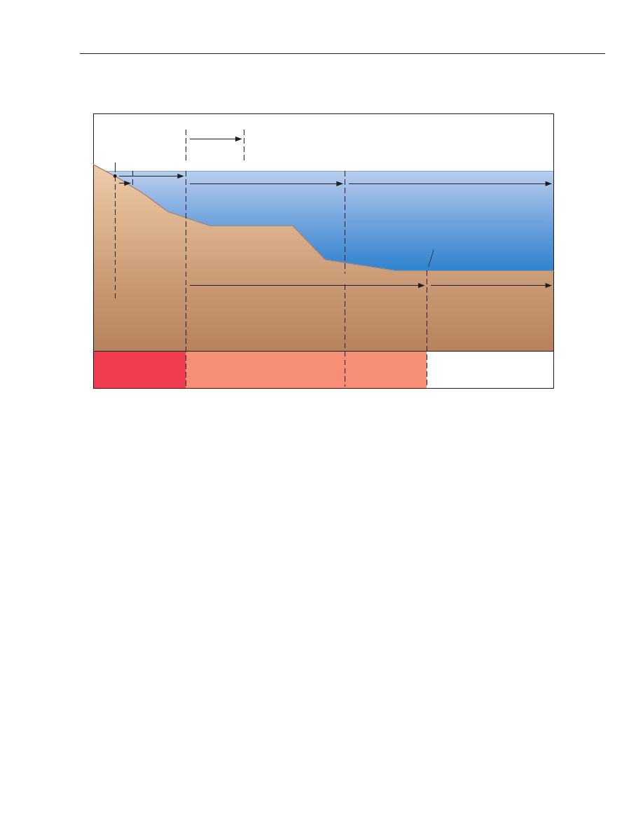
shelf, the high seas and the Area (see Figure 1). The fol-
lowing zones are depicted on NOAA's nautical charts:
internal waters, territorial sea, contiguous zone, and
exclusive economic zone. The limits of these zones are
subject to modification as depicted on future charts;
limits shown on the most recent chart edition take pre-
cedence.
Internal Waters
(500)
Internal waters are the waters (harbors, bays, and
rivers) on the landward side of the baseline from which
the breadth of the territorial sea is measured. The
United States has full sovereignty over its internal wa-
ters and ports as if they were part of its land territory.
NOAA's nautical charts depict the baseline from which
the limits of the U.S. territorial sea, contiguous zone,
and exclusive economic zone are measured as well as
the Three Nautical Mile Line and Natural Resources
Boundary, as described below.
Territorial Sea
(501)
The territorial sea of the United States extends be-
yond the land territory and internal waters, and also in-
cludes the Commonwealth of Puerto Rico, Guam,
American Samoa, the U.S. Virgin Islands, the Com-
monwealth of the Northern Mariana Islands, and any
other territory or possession over which the United
States exercises sovereignty. (Presidential Proclama-
tion No. 5928. December 27, 1988.) The United States
exercises sovereignty over the territorial sea that ex-
tends to the airspace over the area, and to the bed and
subsoil. Under customary international law as reflected
in the 1982 United Nations Convention on the Law of
the Sea (UNCLOS), the territorial sea of the United
States extends to 12 nautical miles (nm) from the base-
line from which the breadth of the territorial sea is
measured; determined in accordance with interna-
tional law except as otherwise established in a mari-
time boundary treaty of the United States. While the
United States may adopt certain laws and regulations,
vessels of all countries navigating through the territo-
rial sea enjoy the right of innocent passage; vessels and
aircraft of all countries enjoy the right of transit
passage through international straits.
Contiguous Zone
(502)
The contiguous zone of the United States is a zone
measured 24 nm from the territorial sea baseline and is
contiguous to the territorial sea of the United States,
including the Commonwealth of Puerto Rico, Guam,
American Samoa, the U.S. Virgin Islands, the Com-
monwealth of the Northern Mariana Islands, and any
other territory or possession over which the United
States exercises sovereignty. (Presidential Proclama-
tion No. 7219. August 2, 1999.) Under customary law as
reflected in UNCLOS, the U.S. may exercise the control
necessary to prevent infringement of its customs, fis-
cal, immigration, or sanitary laws and regulations
General Information
■
Chapter 1
■
33
09-3603-1
Sovereign
Territory
Sovereign rights to the water
column and continental shelf
No national rights
To 200nm inherent sovereign rights for
exploring and exploiting non-living
resources of seabed and subsoil,
plus sedentary species
Sovereign rights to
the continental shelf
Beyond 200nm
submission required
to the Commission
on the Limits of the
Continental Shelf to
confirm rights
Seabed and subsoil non-living
resources administered by the
International Seabed Authority
Territorial
Sea
Baseline
Territorial
Sea
State/
Territory
Coastal Waters
Water column beyond national jurisdiction
Contiguous
Zone
Exclusive Economic Zone
The High Seas
Continental Shelf
The Area
Sovereign rights for exploring, exploiting,
conserving and managing living and
non-living resources of the water column
and underlying continenetal shelf
Sovereignty extends
to the air space,
water column,
seabed and subsoil
allowing for the right
of innocent passage
12nm
24nm
1 nautical mile (nm) = 1852 meters (m)
Limited
enforcement
zone
Scale of Rights
3nm
200nm
To outer edge of continental margin
up to a maximum of 350nm from the
TSB of 100nm beyond the 2,500m
isobath, whichever is the greatest
Figure 1: Offshore extent of the maritime zones recognized under international law

within its territory or territorial sea, and to punish in-
fringement of these laws and regulations committed
within its territory or territorial sea. The United States
may also prescribe and enforce laws against foreign
flagged vessels and nationals to protect the underwater
cultural heritage to the outer boundary of the
contiguous zone (24 nm).
Exclusive Economic Zone
(503)
The exclusive economic zone of the United States
extends no more than 200 nm from the territorial sea
baseline and is adjacent to the 12 nm territorial sea of
the United States, including the Commonwealth of
Puerto Rico, Guam, American Samoa, the U.S. Virgin
Islands, the Commonwealth of the Northern Mariana
Islands, and any other territory or possession over
which the United States exercises sovereignty. (Presi-
dential Proclamation No. 5030 of March 10, 1983 and
Federal Register, volume 60 - number 163, August 23,
1995, “Exclusive Economic Zone and Maritime Bound-
aries: Notice of Limits”) As such, the exclusive eco-
nomic zone overlaps the 12 nm - 24 nm contiguous
zone.
(504)
Within the EEZ, the U.S. has (a) sovereign rights
for the purpose of exploring, exploiting, conserving and
managing natural resources, whether living and non-
living, of the seabed and subsoil and the superjacent
waters and with regard to other activities for the eco-
nomic exploitation and exploration of the zone, such as
the production of energy from the water, currents and
winds; (b) jurisdiction as provided for in international
and domestic laws with regard to the establishment
and use of artificial islands, installations, and struc-
tures, marine scientific research, and the protection
and preservation of the marine environment; and (c)
other
rights
and
duties
provided
for
under
international and domestic laws.
(505)
Note: In certain U.S. fisheries laws, the term “ex-
clusive economic zone” (“EEZ”) is used. While its
outer limit is the same as the EEZ on NOAA charts, the
inner limit generally extends landward to the seaward
boundary of the coastal states of the U.S.
Three Nautical Mile Line
(506)
The Three Nautical Mile Line, as measured from
the territorial sea baseline and previously identified as
the outer limit of the U.S. territorial sea, is retained on
charts because it continues to be used in certain federal
laws.
(507)
Note: Since the “coast line,” a term used in the
Submerged Lands Act, and the baseline are determined
using the same criteria under international law, the
Three Nautical Mile Line is generally the same as the
seaward boundary of states under the Submerged
Lands Act. There are exceptions; therefore, the Three
Nautical Mile Line does not necessarily depict the sea-
ward limit of states under the Submerged Lands Act.
Natural Resources Boundary
(508)
The 9 M Natural Resources Boundary is the sea-
ward limit of the submerged lands of Puerto Rico,
Texas, and the Gulf coast of Florida. It coincides with
the inner limit of the U.S. outer continental shelf under
the Outer Continental Shelf Lands Act.
Marine Protected Area (MPA)
(509)
Marine Protected Areas (MPAs) are particular
places in ocean, coastal and estuarine ecosystems
where vital natural and cultural resources are given
greater protection than in surrounding waters. MPAs
have been established in the U.S. for more than a cen-
tury. Currently, there are over 1,600 MPAs in U.S. ma-
rine waters and the Great Lakes, with levels of
protection ranging from a few "no-take" areas that pro-
hibit all extractive uses, to the more common multiple
use areas that allow vessel access, anchoring, fishing
and non-consumptive activities. MPAs are managed by
dozens of Federal, state, tribal and local authorities.
For detailed information on MPA locations, types, in-
teractive map, purposes and legal restrictions, visit
http://mpa.gov/.
Archaeological Resource Preservation
(510)
Under Federal and State laws it is illegal to destroy,
deface, collect, transport, sell or trade archaeological,
cultural, submerged and historic resources without
authorization. Applicable laws include, but are not lim-
ited to, the Historic Sites Act, the Archaeological Re-
source
Protection
Act,
the
National
Historic
Preservation Act, the Abandoned Shipwreck Act, and
the Sunken Military Craft Act. These laws protect ar-
chaeological resources on lands administered by the
National Park Service, U.S. Fish and Wildlife Service,
Bureau of Land Management, and National Marine
Sanctuaries as well as State, private and Native lands.
For further information, consult individual state ar-
chaeology offices at http://www.uiowa.edu/~osa/nasa/.
U.S. GOVERNMENT AGENCIES PROVIDING
MARITIME SERVICES
DEPARTMENT OF AGRICULTURE
Animal and Plant Health Inspection Service
(511)
The Animal and Plant Health Inspection Service is re-
sponsible for protecting the Nation’s animal population,
34
■ Chapter 1
■
Volume 5

General Information
■
Chapter 1
■
35
food and fiber crops, and forests from invasion by for-
eign pests. They administer agricultural quarantine
and restrictive orders issued under authority provided
in various acts of Congress. The regulations prohibit or
restrict the importation or interstate movement of live
animals, meats, animal products, plants, plant prod-
ucts, soil, injurious insects, and associated items that
may introduce or spread plant pests and animal dis-
eases which may be new to or not widely distributed
within the United States or its territories. Inspectors
examine imports at ports of entry as well as the vessel,
its stores, and crew or passenger baggage.
(512)
The Service also provides an inspection and certifi-
cation service for exporters to assist them in meeting
the quarantine requirements of foreign countries. (See
Appendix A for a list of ports where agricultural inspec-
tors are located and inspections conducted.)
DEPARTMENT OF COMMERCE
National Oceanic and Atmospheric Administration
(NOAA)
(513)
The National Oceanic and Atmospheric Adminis-
tration (NOAA) conducts research and gathers data
about the global oceans, atmosphere, space, and sun,
and applies this knowledge to improve our understand-
ing and stewardship of the environment.
(514)
NOAA provides services to the nation and the pub-
lic through five major organizations: the National
Ocean Service, the National Weather Service, the Na-
tional Marine Fisheries Service, the National Environ-
mental Satellite, Data and Information Service, and
NOAA Research; and numerous special program units.
In addition, NOAA research and operational activities
are supported by the Nation’s seventh uniformed ser-
vice, the NOAA Corps, a commissioned officer corps of
men and women who operate NOAA ships and aircraft,
and serve in scientific and administrative positions.
National Ocean Service (NOS)
(515)
The National Ocean Service's primary concern is
the health and safety of our Nation's coastal and oce-
anic environment. Within NOS, the Office of Coast
Survey is responsible for producing and maintaining
the suite of over 1000 nautical charts, and the Coast Pi-
lots that cover the coastal waters of the U.S. and its ter-
ritories. Nautical charts are published primarily for the
use of the mariner, but serve the public interest in
many other ways. Cartographers in Coast Survey re-
ceive and compile information from a variety of gov-
ernment and non-governmental sources for portrayal
on nautical charts and the Coast Pilots. In addition,
Coast Survey hydrographers, as well as private contrac-
tors, conduct new surveys that are used to update these
products. The principal facilities of Coast Survey are lo-
cated at NOAA headquarters in Silver Spring, MD, Nor-
folk, VA (Marine Operations Center Atlantic), and
Seattle, WA (Marine Operations Center Pacific). NOAA
ships are based at the marine centers.
(516)
Sales agents for NOAA nautical charts and the
Coast Pilot are located in many U.S. ports and in some
foreign ports. Five regional catalogs showing the limits
of NOAA nautical charts are available free from:
FAA/National Aeronautical Navigation Services. (See
Appendix A for list of catalogs and address for ordering,
or call 800-638-8972.) Local authorized sales agents
can
be
located
using
the
query
form
at
http://aeronav.faa.gov/agents.asp. This form is used to
locate aeronautical and nautical sales agents so the
“Nautical Agents” button must be selected.
(517)
The Center for Operational Oceanographic Prod-
ucts and Services (CO-OPS) collects and distributes
observations and predictions of water levels and cur-
rents to ensure safe, efficient and environmentally
sound maritime commerce. Users can find a variety of
information, including water level, tidal predictions,
observed water levels and currents data, tides online
(including a listing of all water level stations currently
in storm surge mode), sea levels online, Great Lakes
online, and PORTS at http://www.tidesandcurrents.
noaa.gov.
(518)
PORTS
®
(Physical Oceanographic Real-Time Sys-
tem) is a centralized data acquisition and dissemina-
tion system that provides real-time water levels,
currents, and other oceanographic and meteorological
data from bays and harbors. This information is pro-
vided via telephone voice response (for most ports) and
the Internet. Accurate real-time water level informa-
tion allows U.S. port authorities and maritime shippers
to make sound decisions regarding loading of tonnage
(based on available bottom clearance), maximizing
loads, and limiting passage times, without compromis-
ing safety.
(519)
There are PORTS systems in 20 areas of the United
States. The table below lists the ports and the telephone
number for voice access to the PORTS data.
(520)
Tide Tables are computed annually by NOAA and
published in October for the upcoming year. These ta-
bles include predicted times and heights of high and
low waters for every day in the year for a number of ref-
erence stations and differences for obtaining similar
predictions for numerous other places. They also in-
clude other useful information such as a method of ob-
taining heights of tide at any time, local mean time of
sunrise and sunset for various latitudes, reduction of

36
■ Chapter 1
■
Volume 5
local mean time to standard time, and time of moonrise
and moonset for various ports.
(521)
Caution–When using the Tide Tables, slack water
should not be confused with high or low water. For
ocean stations there is usually little difference between
the time of high or low water and the beginning of ebb
or flood currents; but for places in narrow channels,
landlocked harbors, or on tidal rivers, the time of slack
current may differ by several hours from the time of
high or low water. The relation of the times of high or
low water to the turning of the current depends upon a
number of factors, so that no simple general rule can be
given. (To obtain the times of slack water, refer to the
Tidal Current Tables.)
(522)
Tidal Current Tables for the coasts of the United
States are computed annually by NOAA and published
in October for the upcoming year. These tables include
daily predictions of the times of slack water and the
times and velocities of strength of flood and ebb cur-
rents for a number of waterways, together with differ-
ences for obtaining predictions for numerous other
places. Also included is other useful information such
as a method for obtaining the velocity of current at any
time, duration of slack, coastal tidal currents, wind
currents, combination of currents and current dia-
grams. Some information on the Gulf Stream is
included in the tables for the Atlantic coast.
(523)
NOAA Tide Tables and Tidal Current Tables for U.S.
waters contain the text of all active Notice to Mariners
which affect the accuracy and use of tide and tidal cur-
rent predictions they contain. (See Appendix A for list
of NOAA Tide and Tidal Current Tables.)
(524)
Many local publishers and printers throughout the
country publish regional and localized tide and tidal
current predictions in booklet, calendar and other for-
mats. The data printed in these local and regional pub-
lications is, in many cases, obtained directly from
NOAA. For availability of localized prediction tables
consult marinas and marine supply companies in your
area.
National Weather Service (NWS)
National Data Buoy Center Meteorological Buoys
(525)
The National Data Buoy Center (NDBC) deploys
moored meteorological buoys which provide weather
data directly to the mariner as well as to marine fore-
casters. In 1998, a disproportionate number of these
buoys have had mooring failures due to abrasion of the
nylon mooring line by trawls, tow lines, etc.
(526)
These buoys have a watch circle radius (WCR) of
2,000 to 4,000 yards from assigned position (AP). In ad-
dition, any mooring in waters deeper than 1,000 feet
will have a floating “loop” or catenary that may be as lit-
tle as 500 feet below the surface. This catenary could be
anywhere within the buoy’s WCR. Any underwater ac-
tivity within this radius may contact the mooring caus-
ing a failure.
(527)
To avoid cutting or damaging a moor, mariners are
urged to exercise extreme caution when navigating in
the vicinity of meteorological buoys and to remain well
clear of the watch circle. If a mooring is accidentally
contacted or cut, please notify NDBC at 228-688-2835
or 228-688-2436.
(528)
For further information relating to these buoys
visit http://seaboard.ndbc.noaa.
Marine Weather Forecasts
(529)
The National Weather Service provides marine
weather forecasts and warnings for the U.S. coastal wa-
ters, the Great Lakes, offshore waters, and high seas ar-
eas. Scheduled marine forecasts are issued four times
daily from National Weather Service Offices with local
areas of responsibility, around the United States,
Guam, American Samoa, and Puerto Rico. (See Appen-
dix A for National Weather Service Offices located in
the area covered by this Coast Pilot.)
Port or Waterway
Voice Access Phone
Number
Anchorage, AK
1-866-257-6787
Cherry Point, WA
1-888-817-7794
Chesapeake Bay
1-866-247-6787
Columbia River, Lower
1-888-537-6787
Delaware River and Bay
1-866-307-6787
Gulfport, MS
1-888-257-1858
Houston/Galveston
1-866-447-6787
Lake Charles
1-888-817-7692
Los Angeles/Long Beach
not available
Mississippi River
1-888-817-7767
Mobile Bay, AL
1-877-847-6787
Narragansett Bay, RI
1-866-757-6787
New Haven, CT
1-888-807-6787
New York/New Jersey Harbor
1-866-217-6787
Pascagoula, MS
1-888-257-1857
Sabine Neches
1-888-257-1859
San Francisco Bay
1-866-727-6787
Soo Locks, MI
1-301-713-9596 (toll)
Tacoma, WA
1-888-607-6787
Tampa Bay, FL
1-866-827-6787

(530)
Typically, the forecasts contain information on
wind speed and direction, wave heights, visibility,
weather, and a general synopsis of weather patterns af-
fecting the region. The forecasts are supplemented
with special marine warnings and statements, radar
summaries, marine observations, small-craft adviso-
ries, gale warnings, storm warnings and various cate-
gories of tropical cyclone warnings e.g., tropical
depression, tropical storm and hurricane warnings.
Specialized products such as coastal flood, seiche, and
tsunami warnings, heavy surf advisories, low water
statements, ice forecasts and outlooks, and lake shore
warnings and statements are issued as necessary. (For
further information, go to http://www.weather.gov/om/
marine/home.htm.)
(531)
The principal means of disseminating marine
weather services and products in coastal areas is NOAA
Weather Radio. This network of more than 900 trans-
mitters, covering all 50 states, adjacent coastal waters,
Puerto Rico, the U.S. Virgin Islands, and the U.S. Pa-
cific Territories, is operated by the NWS and provides
continuous broadcasts of weather information for the
general public. These broadcasts repeat recorded mes-
sages every 4 to 6 minutes. Messages are updated peri-
odically, usually every 2-3 hours and amended as
required to include the latest information. When se-
vere weather threatens, routine transmissions are in-
terrupted and the broadcast is devoted to emergency
warnings. (See Appendix A for NOAA Weather Radio
Stations covered by this Coast Pilot.)
(532)
In coastal areas, the programming is tailored to the
needs of the marine community. Each coastal marine
forecast covers a specific area. For example, “Cape
Henlopen to Virginia Beach, out 20 miles.” The broad-
cast range is about 40 miles from the transmitting an-
tenna site, depending on terrain and quality of the
receiver used. When transmitting antennas are on high
ground, the range is somewhat greater, reaching 60
miles or more. Some receivers are equipped with a
warning alert device that can be turned on by means of
a tone signal controlled by the NWS office concerned.
This signal is transmitted for 13 seconds preceding an
announcement of a severe weather warning.
(533)
Marine weather warnings are displayed to small-
craft operators and others within sight of the shore by
the flags, pennants and lights of the Coastal Warning
Display program. These displays are meant to warn the
public of approaching storm conditions and visually
communicate that citizens should take personal re-
sponsibility for individual safety in the face of an ap-
proaching storm. Anyone observing the signals
displayed by the program is urged to tune to the Na-
tional Weather Service radio broadcasts for the latest
information. (See National Weather Service Coastal
Warning Displays, following, for additional informa-
tion.)
(534)
NWS marine weather products are also dissemi-
nated to marine users through the broadcast facilities
of the Coast Guard, Navy, and commercial marine radio
stations. Details on these broadcasts including times,
frequencies, and broadcast content are listed on the NWS
internet site, Marine Product Dissemination Informa-
tion,
http://www.nws.noaa.gov/om/marine/home.htm.
For marine weather services in the coastal areas, the
NWS publishes a series of Marine Weather Services
Charts showing locations of NOAA Weather Radio sta-
tions, sites, telephone numbers of recorded weather
messages and NWS offices, and other useful marine
weather information.
(535)
Ships of all nations share equally in the effort to re-
port weather observations. These reports enable mete-
orologists to create a detailed picture of wind, wave,
and weather patterns over the open waters that no
other data source can provide and upon which marine
forecasts are based. The effectiveness and reliability of
these forecasts and warnings plus other services to the
marine community are strongly linked to the observa-
tions received from mariners. There is an especially ur-
gent need for ship observations in the coastal waters,
and the NWS asks that these be made and transmitted
whenever possible. Many storms originate and inten-
sify in coastal areas. There may be a great difference in
both wind direction and speed between the open sea,
the offshore waters, and on the coast itself.
(536)
Information on how ships, commercial fishermen,
offshore industries, and others in the coastal zone may
participate in the marine observation program is avail-
able from National Weather Service Port Meteorologi-
cal Officers (PMOs). Port Meteorological Officers are
located in major U.S. port cities where they visit ships
in port to assist masters and mates with the weather
observation program, provide instruction on the inter-
pretation of weather charts, calibrate barometers and
other meteorological instruments, and discuss marine
weather communications and marine weather require-
ments affecting the ships’ operations. (For further in-
formation on the Voluntary Observing Ship Program
and Port Meteorological Officers, go to http://www.vos.
noaa.gov.)
Space Environment Center (SEC)
(537)
The Space Environment Center disseminates space
weather alerts and forecasts (information concerning
solar activity, radio propagation, etc.).
(538)
For general information, see Appendix A for ad-
dress and phone number.
General Information
■
Chapter 1
■
37
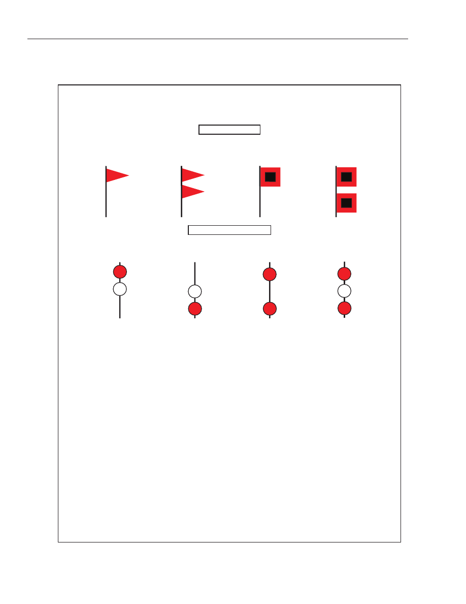
38
■ Chapter 1
■
Volume 5
NATIONAL WEATHER SERVICE COASTAL WARNING DISPLAYS
DAYTIME SIGNALS
SMALL CRAFT
ADVISORY
GALE
WARNING
STORM
WARNING
HURRICANE
WARNING
NIGHT (LIGHT) SIGNALS
GALE
WARNING
STORM
WARNING
SMALL CRAFT
ADVISORY
HURRICANE
WARNING
SMALL CRAFT ADVISORY: An advisory issued by coastal and Great
Lakes Weather Forecast Offi ces (WFO) for areas included in the Coastal
Waters Forecast or Nearshore Marine Forecast (NSH) products. Thresh-
olds governing the issuance of small craft advisories are specifi c to
geographic areas. A Small Craft Advisory may also be issued when sea or
lake ice exists that could be hazardous to small boats. There is no precise
defi nition of a small craft. Any vessel that may be adversely affected by
Small Craft Advisory criteria should be considered a small craft. Other
considerations include the experience of the vessel operator, and the type,
overall size, and sea worthiness of the vessel. There is no legal defi nition
of “small craft”. The Small Craft Advisory is an advisory in Coastal Waters
and Nearshore forecasts for sustained winds, frequent gusts, or sea/wave
conditions, exceeding defi ned thresholds specifi c to geographic areas. A
Small Craft Advisory may also be issued when sea or lake ice exists that
could be hazardous to small boats.
Eastern (ME to SC, Lake Erie, Lake Ontario) – Sustained winds or frequent
gusts ranging between 25 and 33 knots (except 20 to 25 knots, lower
threshold area dependent, to 33 knots for harbors, bays, etc.) and/or seas
or waves 5 to 7 feet and greater, area dependent.
Central (MN to OH) – Sustained winds or frequent gusts (on the Great
Lakes) between 22 and 33 knots inclusive, and/or seas or waves greater
than 4 feet.
Southern (GA to TX and Caribbean) – Sustained winds of 20 to 33 knots,
and/or forecast seas 7 feet or greater that are expected for more than 2
hours.
Western (WA..CA) - Sustained winds of 21 to 33 knots, potentially in com-
bination with wave heights exceeding 10 feet (or wave steepness values
exceeding local thresholds).
Alaska (AK) – Sustained winds or frequent gusts of 23 to 33 knots. A
small craft advisory for rough seas may be issued for sea/wave conditions
deemed locally signifi cant, based on user needs, and should be no lower
than 8 feet.
Hawaii (HI), Samoa – Sustained winds 25 knots or greater and seas 10
feet or greater.
Guam and the Northern Mariana Islands – Sustained winds 22 to 33 knots
and/or combined seas of 10 feet or more. “Frequent gusts”are typically
long duration conditions (greater than 2 hours).
For a list of NWS Weather Offi ces by Region, refer to the following website:
http://www.nws.noaa.gov/organization.php
GALE WARNING: To indicate winds within the range 34 to 47 knots are
forecast for the area.
STORM WARNING: To indicate winds 48 knots and above, no matter how
high the speed, are forecast for the area. However, if the winds are associ-
ated with a tropical cyclone (hurricane), the STORM WARNING indicates
that winds within the range 48-63 knots are forecast.
HURRICANE WARNING: Issued only in connection with a tropical cyclone
(hurricane) to indicate that winds 64 knots and above are forecast for the
area.
NOTE: A “HURRICANE WATCH” is an announcement issued by the
National Weather Service via press and television broadcasts whenever a
tropical storm or hurricane becomes a threat to a coastal area. The “Hur-
ricane Watch” announcement is not a warning, rather it indicates that the
hurricane is near enough that everyone in the area covered by the “Watch”
should listen to their radios for subsequent advisories and be ready to take
precautionary action in case hurricane warnings are issued.
NOTE: A SPECIAL MARINE WARNING is issued whenever a severe local
storm or strong wind of brief duration is imminent and is not covered by ex-
isting warnings or advisories. No visual displays will be used in connection
with the Special Marine Warning Bulletin; boaters will be able to receive
thesespecial warnings by keeping tuned to a NOAA Weather Radio station
or to Coast Guard and commercial radio stations that transmit marine
weather information.

National Environmental Satellite, Data, and
Information Service (NESDIS)
(539)
Among its functions, NESDIS archives, processes,
and disseminates the non-realtime meteorological and
oceanographic data collected by government agencies
and private institutions. Marine weather observations
are collected from ships at sea on a voluntary basis.
About one million observations are received annually
at NESDIS’s National Climatic Center. They come from
vessels representing every maritime nation. These ob-
servations, along with land data, are returned to the
mariners in the form of climatological summaries and
atlases for coastal and ocean areas. They are available in
such NOAA publications as the U.S. Coast Pilot, Mari-
ners Weather Log, and Local Climatological Data, An-
nual Summary. They also appear in the National
Geospatial-Intelligence Agency’s Pilot Chart Atlases
and Sailing Directions Planning Guides.
DEPARTMENT OF DEFENSE
National Geospatial-Intelligence Agency (NGA)
(540)
The National Geospatial-Intelligence Agency pro-
vides hydrographic, navigational, topographic, and
geodetic data, charts, maps, and related products and
services to the Armed Forces, other Federal Agencies,
the Merchant Marine and mariners in general. Publica-
tions include Sailing Directions, List of Lights, Dis-
tances Between Ports, Radio Navigational Aids,
International Code of Signals, American Practical Nav-
igator (Bowditch), and Notice to Mariners. (See Na-
tional Geospatial-Intelligence Agency Procurement
Information in Appendix A.)
U.S. Army Corps of Engineers (USACE)
(541)
The U.S. Army Corps of Engineers has charge of the
improvement of the rivers and harbors of the United
States and of miscellaneous other civil works which in-
clude the administration of certain Federal laws en-
acted for the protection and preservation of navigable
waters of the United States; the establishment of regu-
lations for the use, administration, and navigation of
navigable waters; the establishment of harbor lines; the
removal of sunken vessels obstructing or endangering
navigation; and the granting of permits for structures
or operations in navigable waters, and for discharges
and deposits of dredged and fill materials in these waters.
(542)
Restricted areas in most places are defined and
regulations governing them are established by the U.S.
Army Corps of Engineers. The regulations are enforced
by the authority designated in the regulations, and the
areas are shown on the large-scale charts of NOS. Cop-
ies of the regulations may be obtained at the District
offices of the U.S. Army Corps of Engineers. The regula-
tions also are included in the appropriate Coast Pilot.
(543)
Information concerning the various ports, im-
provements, channel depths, navigable waters, and the
condition of the Intracoastal Waterways in the areas
under their jurisdiction may be obtained direct from
the District Engineer Offices. (See Appendix A for ad-
dresses.)
(544)
The U.S. Army Corps of Engineers has general su-
pervision of location, construction, and manner of
maintenance of all traps, weirs, pounds, or other fish-
ing structures in the navigable waters of the United
States. Where State and/or local controls are sufficient
to regulate these structures, including that they do not
interfere with navigation, the U.S. Army Corps of Engi-
neers leaves such regulation to the State or local au-
thority. (See 33 CFR 330 (not carried in this Pilot) for
applicable Federal regulations.) Construction permits
issued by the Engineers specify the lights and signals
required for the safety of navigation.
(545)
Fish havens, artificial reefs constructed to attract
fish, can be established in U.S. coastal waters only as
authorized by a U.S. Army Corps of Engineers permit;
the permit specifies the location, extent, and depth over
these mounds of rubble.
U.S. Naval Observatory
(546)
The United States Naval Observatory (USNO) pro-
vides a wide range of astronomical data and products,
and serves as the official source of time for the U.S. De-
partment of Defense and a Standard of time for the en-
tire United States. The USNO provides earth
orientation products such as the latest 24-hour and
48-hour sets of GPS satellite orbits, the latest determi-
nations and predictions for polar motion, and informa-
tion for GPS users. The USNO also maintains a
reference for precise time (USNO Master Clock) and
monitors the GPS constellation. For extensive infor-
mation on the USNO products available, visit
http://www.usno.navy.mil/ or contact by telephone at
202-762-1467.
DEPARTMENT OF HEALTH AND HUMAN
SERVICES
Food and Drug Administration (FDA)
(547)
Under the provisions of the Control of Communi-
cable Diseases Regulations (21 CFR 1240) and Inter-
state Conveyance Sanitation Regulations (21 CFR
1250), vessel companies operating in interstate traffic
General Information
■
Chapter 1
■
39

shall obtain potable water for drinking and culinary
purposes only at watering points found acceptable to
the Food and Drug Administration. Water supplies
used in watering point operations must also be in-
spected to determine compliance with applicable Inter-
state Quarantine Regulations (42 CFR 72). These
regulations are based on authority contained in the
Public Health Service Act (PL 78–410). Penalties for vi-
olation of any regulation prescribed under authority of
the Act are provided for under Section 368 (42 USC
271) of the Act.
(548)
FDA annually publishes a list of Acceptable Vessel
Watering Points. This list is available from most FDA
offices or from Interstate Travel Sanitation Subpro-
gram Center for Food Safety and Applied Nutrition,
FDA (HFF-312), 200 C Street SW., Washington, DC
20204. Current status of watering points can be ascer-
tained by contacting any FDA office. (See Appendix A
for addresses.)
Public Health Service
(549)
The Public Health Service administers foreign
quarantine procedures at U.S. ports of entry.
(550)
All vessels arriving in the United States are subject
to public health inspection. Vessels subject to routine
boarding for quarantine inspection are only those
which have had on board during the 15 days preceding
the date of expected arrival or during the period since
departure (whichever period of time is shorter) the oc-
currence of any death or ill person among passengers
or crew (including those who have disembarked or
have been removed). The master of a vessel must report
such occurrences immediately by radio to the quaran-
tine station at or nearest the port at which the vessel
will arrive.
(551)
In addition, the master of a vessel carrying 13 or
more passengers must report by radio 24 hours before
arrival the number of cases (including zero) of diarrhea
in passengers and crew recorded in the ship’s medical
log during the current cruise. All cases that occur after
the 24 hour report must also be reported not less than 4
hours before arrival.
(552)
Ill person means person who:
(553)
1. Has a temperature of 100°F (or 38°C) or greater,
accompanied by a rash, glandular swelling, or jaundice,
or which has persisted for more than 48 hours; or
(554)
2. Has diarrhea, defined as the occurrence in a 24
hour period of three or more loose stools or of a greater
than normal (for the person) amount of loose stools.
(555)
Vessels arriving at ports under control of the
United States are subject to sanitary inspection to de-
termine whether measures should be applied to
prevent the introduction, transmission, or spread of
communicable disease.
(556)
Specific public health laws, regulations, policies,
and procedures may be obtained by contacting U.S.
Quarantine Stations, U.S. Consulates or the Chief Pro-
gram Operations, Division of Quarantine, Centers for
Disease Control, Atlanta, Ga. 30333. (See Appendix A
for addresses of U.S. Public Health Service Quarantine
Stations.)
DEPARTMENT OF HOMELAND SECURITY
U.S. Citizenship and Immigration Services
(557)
The Immigration and Naturalization Service ad-
ministers the laws relating to admission, exclusion,
and deportation of aliens, the registration and finger-
printing of aliens, and the naturalization of aliens law-
fully resident in the United States.
(558)
The designated ports of entry for aliens are divided
into three classes. Class A is for all aliens. Class B is
only for aliens who at the time of applying for admis-
sion are lawfully in possession of valid resident aliens’
border-crossing identification cards or valid nonresi-
dent aliens’ border-crossing identification cards or are
admissible without documents under the documentary
waivers contained in 8 CFR 212.1(a). Class C is only
for aliens who are arriving in the United States as crew-
men as that term is defined in Section 101(a) (10) of the
Immigration and Nationality Act. (The term crewman
means a person serving in any capacity on board a ves-
sel or aircraft.) No person may enter the United States
until he has been inspected by an immigration officer.
A list of the offices covered by this Coast Pilot is given
in Appendix A.
U.S. Coast Guard
(559)
The Coast Guard has among its duties the enforce-
ment of the laws of the United States on the high seas
and in coastal and inland waters of the U.S. and its pos-
sessions; enforcement of navigation and neutrality
laws and regulations; establishment and enforcement
of navigational regulations upon the Inland Waters of
the United States, including the establishment of a de-
marcation line separating the high seas from waters
upon which U.S. navigational rules apply; administra-
tion of the Oil Pollution Act of 1990, as amended; estab-
lishment and administration of vessel anchorages;
approval of bridge locations and clearances over navi-
gable waters; administration of the alteration of ob-
structive bridges; regulation of drawbridge operations;
inspection of vessels of the Merchant Marine; admea-
surement of vessels; documentation of vessels; prepa-
ration and publication of merchant vessel registers;
40
■ Chapter 1
■
Volume 5

registration of stack insignia; port security; issuance of
Merchant Marine licenses and documents; search and
rescue operations; investigation of marine casualties
and accidents, and suspension and revocation proceed-
ings; destruction of derelicts; operation of aids to navi-
gation; publication of Light Lists and Local Notices to
Mariners; and operation of ice-breaking facilities.
(560)
The Coast Guard, with the cooperation of coast ra-
dio stations of many nations, operates the Automated
Mutual-assistance Vessel Rescue System (AMVER). It
is an international maritime mutual assistance program
which provides important aid to the development and
coordination of search and rescue (SAR) efforts in
many offshore areas of the world. Merchant ships of all
nations making offshore passages are encouraged to
voluntarily send movement (sailing) reports and peri-
odic position reports to the AMVER Center at Coast
Guard New York via selected radio stations. Informa-
tion from these reports is entered into an electronic
computer which generates and maintains dead reckon-
ing positions for the vessels. Characteristics of vessels
which are valuable for determining SAR capability are
also entered into the computer from available sources
of information.
(561)
A worldwide communications network of radio sta-
tions supports the AMVER System. Propagation condi-
tions, location of vessel, and traffic density will
normally determine which station may best be con-
tacted to establish communications. To ensure that no
charge is applied, all AMVER reports should be passed
through specified radio stations. Those stations which
currently accept AMVER reports and apply no coastal
station, ship station, or landline charge are listed in
each issue of the “AMVER Bulletin” publication. Also
listed are the respective International radio call signs,
locations, frequency bands, and hours of operation.
The “AMVER Bulletin” is available from AMVER Mari-
time Relations, U.S. Coast Guard, Battery Park Build-
ing New York, NY 10004, TEL: 212-668-7764, FAX
212-668-7684. Although AMVER reports may be sent
through nonparticipating stations, the Coast Guard
cannot reimburse the sender for any charges applied.
(562)
Information concerning the predicted location and
SAR characteristics of each vessel known to be within
the area of interest is made available upon request to
recognized SAR agencies of any nation or vessels need-
ing assistance. Predicted locations are only disclosed
for reasons related to marine safety.
(563)
Benefits of AMVER participation to shipping in-
clude: (1) improved chances of aid in emergencies, (2)
reduced number of calls for assistance to vessels not fa-
vorably located, and (3) reduced time lost for vessels re-
sponding to calls for assistance. An AMVER participant
is under no greater obligation to render assistance dur-
ing an emergency than a vessel who is not participating.
(564)
All AMVER messages should be addressed to Coast
Guard New York regardless of the station to which the
message is delivered, except those sent to Canadian sta-
tions which should be addressed to AMVER Halifax or
AMVER Vancouver to avoid incurring charges to the
vessel for these messages.
(565)
Instructions guiding participation in the AMVER
System are available in the following languages: Chi-
nese, Danish, Dutch, English, French, German, Greek,
Italian, Japanese, Korean, Norwegian, Polish, Portu-
guese, Russian, Spanish, and Swedish. The AMVER Us-
ers Manual is available from: AMVER Maritime
Relations; Commander, Atlantic Area, U.S. Coast
Guard, Federal Building, 431 Crawford Street,
Portsmouth, VA 23704-5004; Commander, Pacific Area,
U.S. Coast Guard, Coast Guard Island, Alameda, CA.
94501-5100; and at U.S. Coast Guard Sectors in major
U.S. ports. Requests for instructions should state the
language desired if other than English.
(566)
For AMVER participants bound for U.S. ports there is
an additional benefit. AMVER participation via messages
which include the necessary information is considered
to meet the requirements of 33 CFR 160. (See
160.201, chapter 2, for rules and regulations.)
(567)
AMVER Reporting Required. U.S. Maritime Ad-
ministration regulations effective August 1, 1983, state
that certain U.S. flag vessels and foreign flag “War Risk”
vessels must report and regularly update their voyages
to the AMVER Center. This reporting is required of the
following: (a) U.S. flag vessels of 1,000 gross tons or
greater, operating in foreign commerce; (b) foreign flag
vessels of 1,000 gross tons or greater, for which an In-
terim War Risk Insurance Binder has been issued un-
der the provisions of Title XII, Merchant Marine Act,
1936.
(568)
Details of the above procedures are contained in
the AMVER Users Manual. The system is also published
in NGA Pub. 117.
(569)
Search and Rescue Operation procedures are con-
tained in the International Maritime Organization
(IMO) SAR Manual (MERSAR). U.S. flag vessels may ob-
tain a copy of MERSAR from local Coast Guard Sector
Offices or Marine Safety Units or by writing to U.S.
Coast Guard (CG-534), Washington, DC 20593-0001.
Other flag vessels may purchase MERSAR directly from
IMO.
(570)
The Coast Guard conducts and/or coordinates
search and rescue operations for surface vessels and
aircraft that are in distress or overdue. (See Distress
Signals and Communication Procedures this chapter.)
General Information
■
Chapter 1
■
41

42
■ Chapter 1
■
Volume 5
(571)
Documentation: Issuance of certificates of registry
(more commonly referred to as Certificates of Docu-
mentation) with endorsements indicating eligibility of
vessels that measure at least 5 net tons, to engage in
various trades for commercial vessels and certain rec-
reational vessels that are numbered either by the Coast
Guard or by a State having an approved numbering sys-
tem (the latter is the most common), and the adminis-
tration of the various laws pertaining thereto, are
functions of the Coast Guard and specifically the Na-
tional Vessel Documentation Center. Owners of vessels
may obtain the necessary information from the Na-
tional Vessel Documentation Center either by mail to
the National Vessel Documentation Center, 792 T.J.
Jackson Drive, Falling Waters, WV 25419-9502; via toll
free number 800-799-8362; or via the Internet:
http://www.uscg.mil/hq/cg5/nvdc.
U.S. Customs and Border Protection
(572)
The U.S. Customs and Border Protection adminis-
ters certain laws relating to:
(573)
•
entry and clearance of vessels and permits for
certain vessel movements between points in the United
States
(574)
•
prohibitions against coastwise transportation of
passengers and merchandise
(575)
•
salvage
(576)
•
dredging and towing by foreign vessels
(577)
•
certain activities of vessels in the fishing trade
(578)
•
regular and special tonnage taxes on vessels
(579)
•
landing and delivery of foreign merchandise (in-
cluding unlading, appraisement, lighterage, drayage,
warehousing, and shipment in bond)
(580)
•
collection of customs duties, including duty on
imported pleasure boats and yachts and 50% duty on
foreign repairs to American vessels engaged in trade
(581)
•
customs treatment of sea and ship's stores while
in port and the baggage of crewmen and passengers
(582)
•
illegally imported merchandise
(583)
•
remission of penalties or forfeiture if customs or
navigation laws have been violated.
(584)
The Customs Service also cooperates with many
other Federal agencies in the enforcement of statutes
they are responsible for. Customs districts and ports of
entry, including customs stations, are listed in Appen-
dix A.
(585)
The Customs and Border Protection office may is-
sue, without charge, a cruising license, normally valid
for one year, to a yacht of a foreign country which has a
reciprocal agreement with the United States. A foreign
yacht holding a cruising license is exempt from having
to undergo formal entry and clearance procedures such
as filing manifests and obtaining permits to proceed as
well as from payment of tonnage tax and entry and
clearance fees at all but the first port of entry. These
vessels shall not engage in trade, violate the laws of the
United States, visit a vessel not yet inspected by a Cus-
toms Agent and does, within 24 hours of arrival at each
port or place in the United States, report the fact of ar-
rival to the nearest customhouse. Countries which
have reciprocal agreements granting these privileges
to U.S. yachts are:
Argentina
Honduras
Australia
Ireland
Austria
Italy
Bahama Islands
Jamaica
Belgium
Liberia
Bermuda
Marshall Islands
Canada
Netherlands
Denmark
New Zealand
Finland
Norway
France
Sweden
Germany
Switzerland
Great Britain
Turkey
Greece
(586)
Further information concerning cruising licenses
may be obtained from the headquarters port for the
customs district in which the license is desired or at
http://www.cbp.gov. U.S. yacht owners planning cruises
to foreign ports may contact the nearest customs dis-
trict headquarters as to customs requirements.
ENVIRONMENTAL PROTECTION AGENCY
(EPA)
(587)
The U.S. Environmental Protection Agency pro-
vides coordinated governmental action to assure the
protection of the environment by abating and control-
ling pollution on a systematic basis. The ocean dump-
ing permit program of the Environmental Protection
Agency provides that except when authorized by per-
mit, the dumping of any material into the ocean is pro-
hibited by the “Marine Protection, Research, and
Sanctuaries Act of 1972, Public Law 92–532,” as
amended (33 USC 1401 et seq.).
(588)
Permits for the dumping of dredged material into
waters of the United States, including the territorial
sea, and into ocean waters are issued by the U.S. Army
Corps of Engineers. Permits for the dumping of fill ma-
terial into waters of the United States, including the
territorial sea, are also issued by the U.S. Army Corps of
Engineers. Permits for the dumping of other material

General Information
■
Chapter 1
■
43
in the territorial sea and ocean waters are issued by the
Environmental Protection Agency.
(589)
U.S. Army Corps of Engineers regulations relating
to the above are contained in 33 CFR 323-324; Envi-
ronmental Protection Agency regulations are in 40
CFR 220-229. (See Disposal Sites, this chapter.)
(590)
Persons or organizations who want to file for an ap-
plication for an ocean dumping permit should write the
Environmental Protection Agency Regional Office for
the region in which the port of departure is located.
(See Appendix A for addresses of regional offices and
States in the EPA coastal regions.)
(591)
The letter should contain the name and address of
the applicant; name and address of person or firm; the
name and usual location of the conveyance to be used
in the transportation and dumping of the material in-
volved; a physical description where appropriate; and
the quantity to be dumped and proposed dumping site.
(592)
Everyone who writes EPA will be sent information
about a final application for a permit as soon as possi-
ble. This final application is expected to include ques-
tions about the description of the process or activity
giving rise to the production of the dumping material;
information on past activities of applicant or others
with respect to the disposal of the type of material in-
volved; and a description about available alternative
means of disposal of the material with explanations
about why an alternative is thought by the applicant to
be inappropriate.
FEDERAL COMMUNICATIONS COMMISSION
(FCC)
(593)
The Federal Communications Commission con-
trols non-Government radio communications in the
United States, Guam, Puerto Rico, and the Virgin Is-
lands. Commission inspectors have authority to board
ships to determine whether their radio stations comply
with international treaties, Federal Laws, and Commis-
sion regulations. The commission has field offices in
the principal U.S. ports. (See Appendix A for addresses.)
Information concerning ship radio regulations and ser-
vice documents may be obtained from the Federal Com-
munications Commission, Washington, DC 20554, or
from any of the field offices.

44
■ Chapter 1
■
Volume 5
Wyszukiwarka
Podobne podstrony:
CP5 39ed Ch03 5
CP5 39ed AppendixB 5
CP5 39ed Ch14 5
CP5 39ed Ch11 5
CP5 39ed Ch06 5
CP5 39ed AppendixA 5
CP5 39ed Ch13 5
CP5 39ed Index 5
CP5 39ed Front 5
CP5 39ed Ch12 5
CP5 39ed Ch10 5
CP5 Zakażenia szpitalne, Medycyna Ratunkowa - Ratownictwo Medyczne
CP5 Ostre zapalenie wyrostka robaczkowego., Medycyna Ratunkowa - Ratownictwo Medyczne
CH01
ch01
ch01
ch01
Japanese for Busy People I (ch01 05)
Genomes3e ppt ch01
więcej podobnych podstron