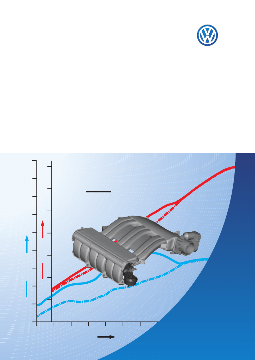
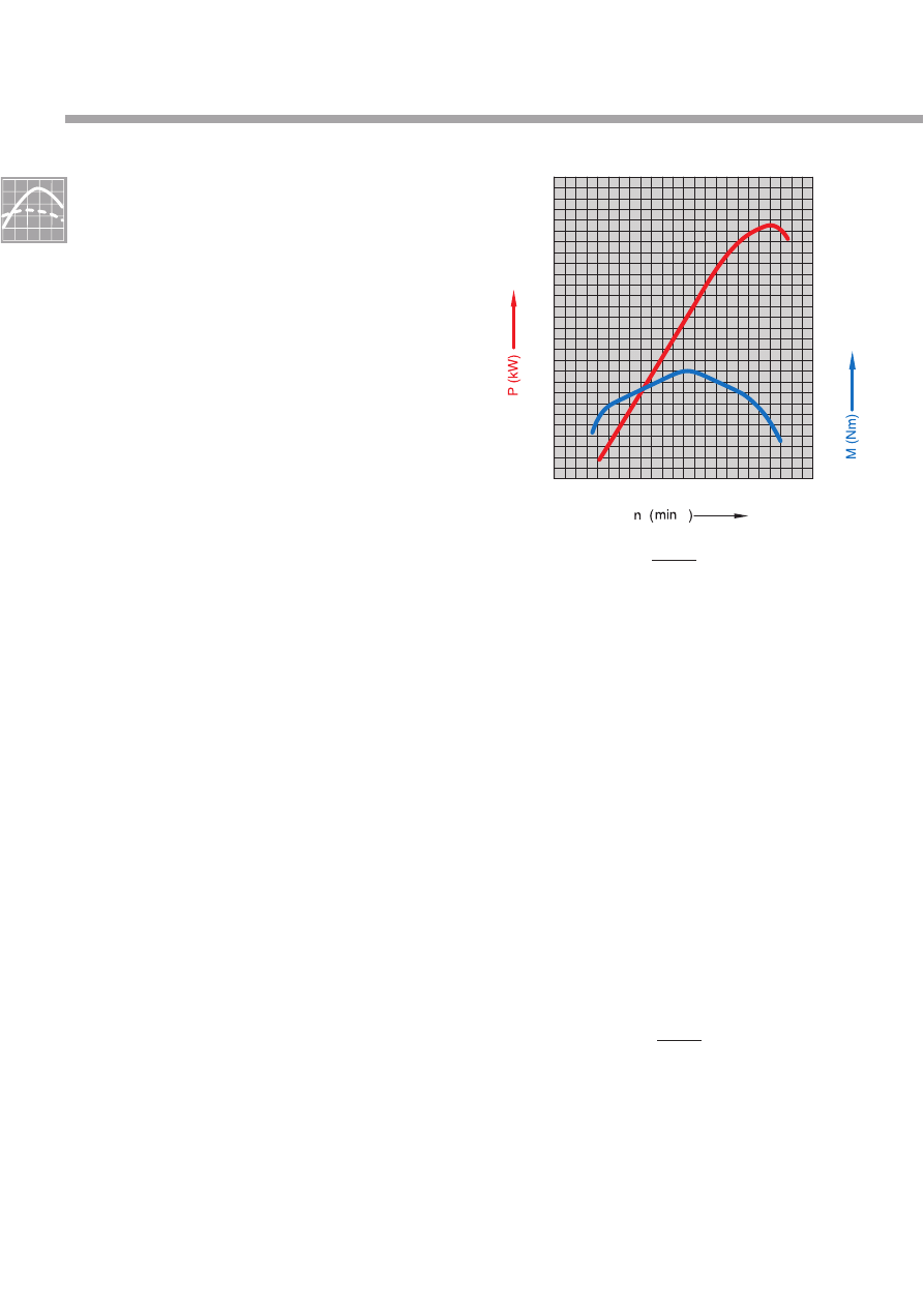
M [Nm]
P [kW]
n [min ]
-1
P =
n • M
9550
[kW]
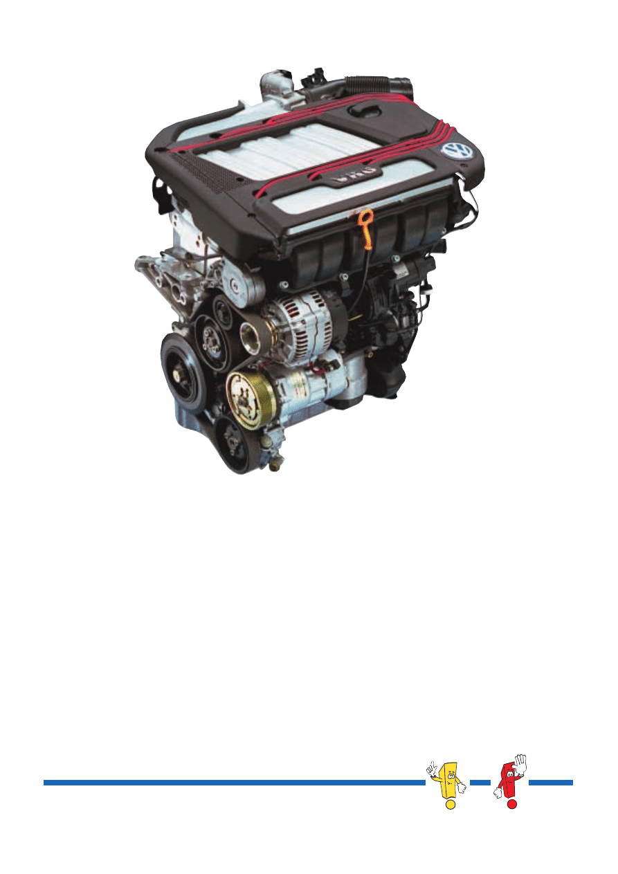
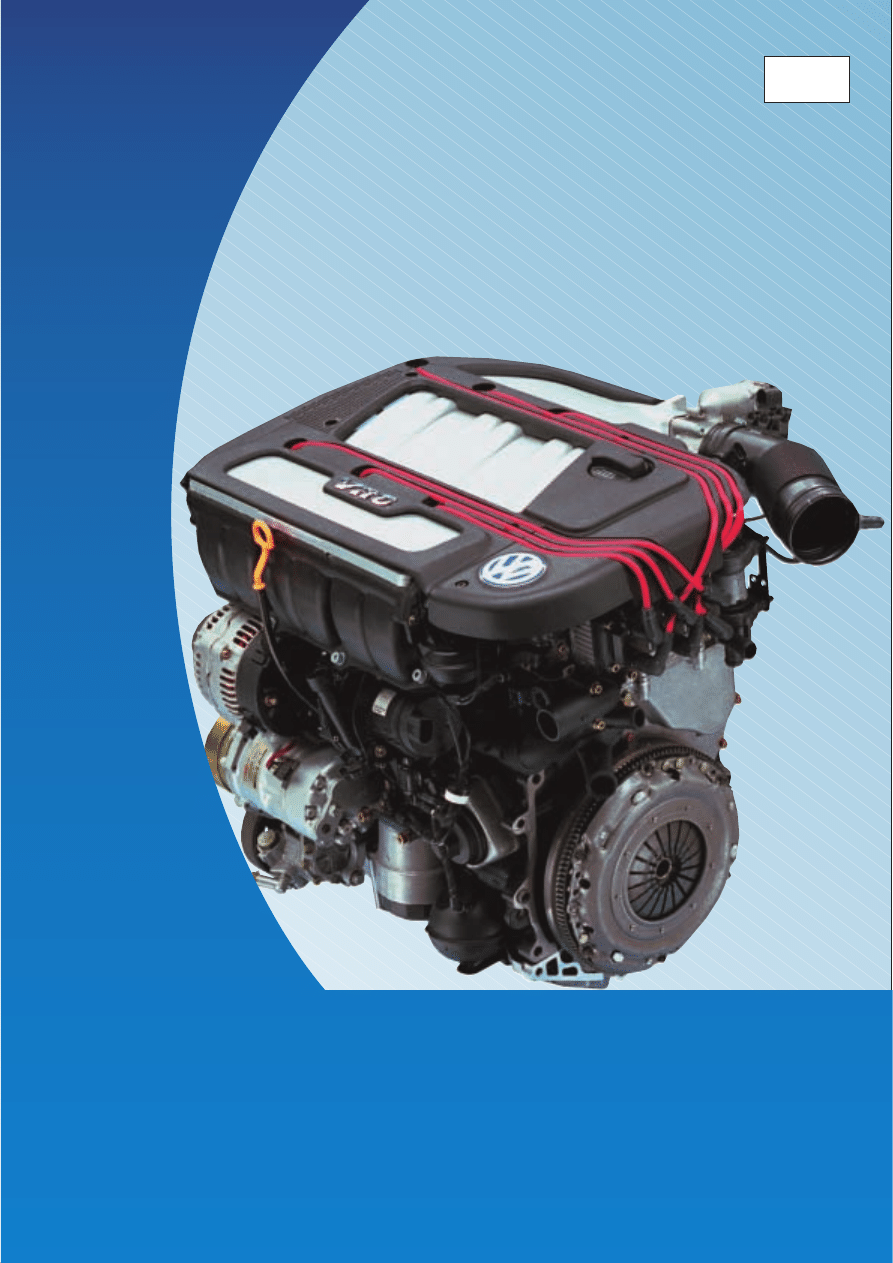
Variable Intake Manifold in VR Engines
Principles and Description of Operation
Self-study programme 212
Service.
2
NEW
Important
Note
This self-study programme explains how it was
possible to optimise the torque and output of the
VR engine with the concept and design of the
new intake manifold and just how an intake tract
affects the air supply.
The VR6 engine, in which the conventional intake
manifold has been replaced by the new variable
intake manifold, provides an example which
makes the increase in power and torque very
clear.
A patent for the variable intake manifold
concept of the VR engine has been applied for.
The output and torque of an engine have the
greatest effect on the engine’s character.
These, in turn, are greatly affected by the degree
to which the cylinder is filled and the geometric
form of the intake tract.
High torque requires an intake manifold with a
geometry different to one for high power output.
A medium intake manifold length with a medium
diameter represents a compromise, but a
variable intake manifold is optimal.
Please always refer to the relevant Service literature
for all inspection, adjustment and repair instructions.
The self-study programme
is not a workshop manual!
212_020

3
Table of contents
Power and torque . . . . . . . . . . . . . . . . . . . . . . . . . . . . . . . . . . . . . 4
Air supply . . . . . . . . . . . . . . . . . . . . . . . . . . . . . . . . . . . . . . . . . . . 5
Air channelling in engine . . . . . . . . . . . . . . . . . . . . . . . . . . . . . . . . . . . . 5
The principle of resonance charging . . . . . . . . . . . . . . . . . . . . . . . . . . 5
The variable intake manifold of the VR engines. . . . . . . . . . . . . 8
Torque position of VR6 variable intake manifold . . . . . . . . . . . . . . . . 9
Power position of VR6 variable intake manifold . . . . . . . . . . . . . . . . . 10
Power and output of VR6 engine . . . . . . . . . . . . . . . . . . . . . . . . . . . . . . .11
Load-dependent change-over concept . . . . . . . . . . . . . . . . . . . . . . . . . 12
Power collector and change-over barrel . . . . . . . . . . . . . . . . . . . . . . . 13
Filling the power collector . . . . . . . . . . . . . . . . . . . . . . . . . . . . . . . . . . . . 14
Intake manifold change-over . . . . . . . . . . . . . . . . . . . . . . . . . . . 15
Intake manifold change-over valve N156 . . . . . . . . . . . . . . . . . . . . . . . 16
Service . . . . . . . . . . . . . . . . . . . . . . . . . . . . . . . . . . . . . . . . . . . . . 17
Test your knowledge . . . . . . . . . . . . . . . . . . . . . . . . . . . . . . . . . . 19
4
n
•
M
9550
P =
[
kW
]
Power and torque
High power and high torque with low fuel con-
sumption are characteristics of a modern car
engine.
How was this goal achieved?
The power P is the product of engine speed n
and torque M.
Greater power can be attained through either
greater torque or higher engine speed.
The numerous moving masses in an engine
(pistons, connecting rods, crankshaft and so on)
limit engine speed.
Thus only torque remains to increase power.
To increase engine torque, one can increase the
displacement or the compression.
Because vehicle taxes are often assessed
according to displacement in spite of technical
advantages, the goal must be attained with a
given displacement in other ways, namely by
increasing the efficiency of the engine.
A flatter torque curve as a function of engine
speed thus becomes the ultimate measure.
One achieves maximum torque through
complete combustion of the fuel-air mixture at
the right moment.
But every complete combustion requires a
certain ratio between air and fuel. The engine
should be provided optimally with air at every
speed.
The volumetric efficiency (VE, represented as
λ
L
in the graphics), makes a qualitative statement
about the air supply:
212_010
m
a
= actual air mass in cylinder in [kg]
m
th
= theoretical air mass in [kg]
-1
m
L
m
th
λ
L
=
n
= engine speed [rpm](min
-1
in graphics)
M = torque [Nm]
9550
= constant derived from the calculation of
all factors when the numerical values for
nare entered in rpm and M, in Nm.
5
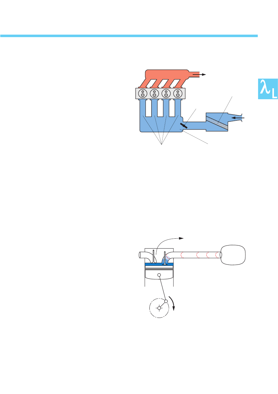
The air supply
Air channelling on engine
The intake system is responsible for feeding the
engine with the air necessary for combustion.
It ensures an even supply of air to all cylinders.
Engines with carburettors or throttle-body
injection also mix fuel with the air in the intake
tract, and a fuel-air mixture is transported.
Intake tracts of multi-point injection systems
transport only air.
This opens substantially more possibilities for
the designer to design the intake manifold in
order to achieve better exploitation of the
self-charging effect of gas momentum.
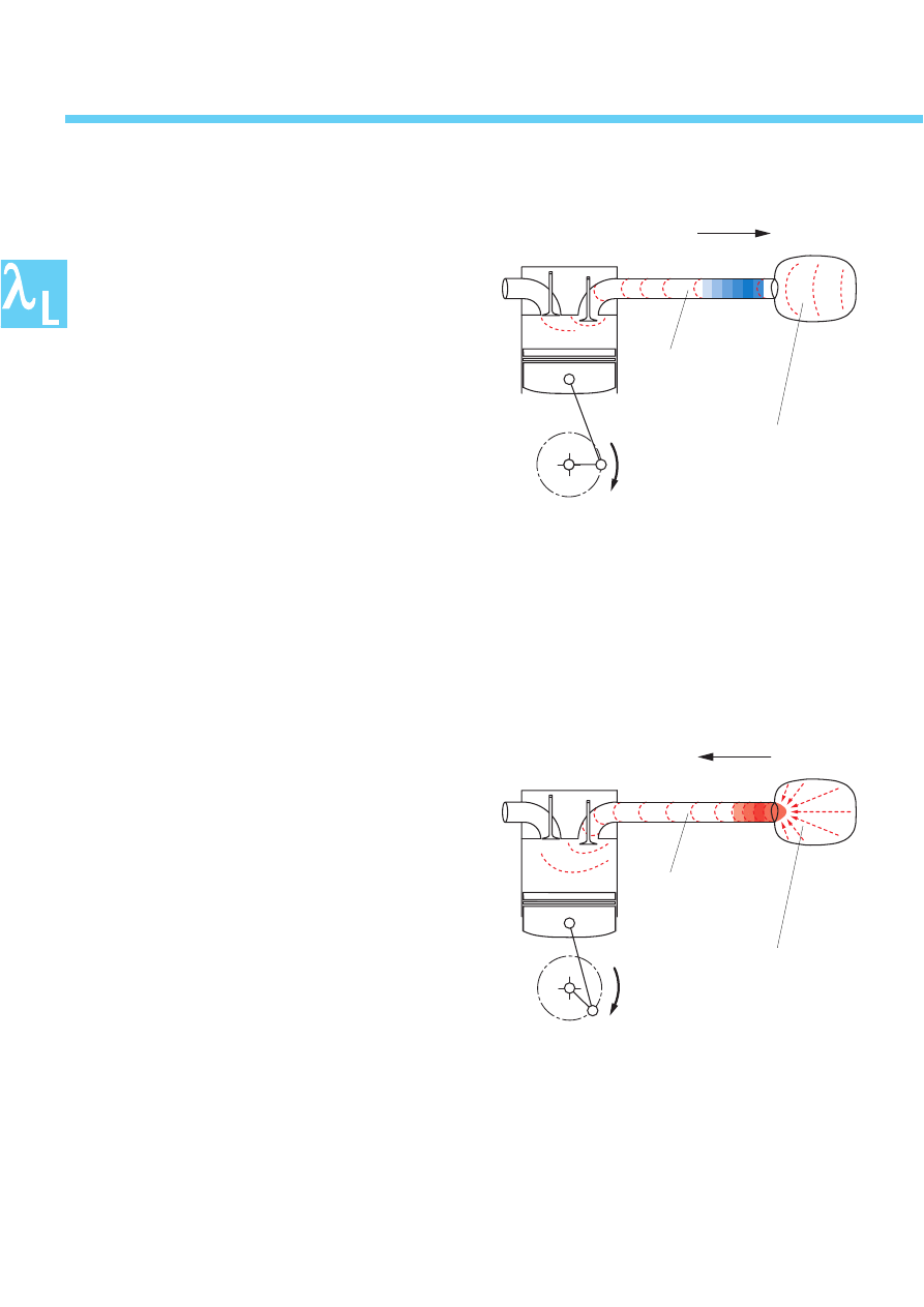
The principle of resonance charging
An intake system works according to the
principle of resonance charging, that is, high
and low-pressure waves are used to charge the
cylinder, in order to achieve greater volumetric
efficiency.
Consider the events in the intake tract.
The inlet valve opens.
The piston moves downwards in the cylinder, in
the direction of bottom dead centre (BDC).
It creates a low-pressure wave in the vicinity of
the inlet valve.
Basic structure of an air channel
on an engine
212_004
Throttle valve
Air filter
Resonance pipes
Collector
Exhaust
Air
212_005
Low pressure wave
Start of resonance charging
6
The air supply
This low-pressure wave propagates itself though
the resonance pipe to the other end, which
protrudes into a collector.
The low-pressure wave at the end of the pipe
acts on the volume of air present in the collector.
The pressure of the volume of air in the collector
is approximately equal to ambient air pressure.
This is significantly higher than the air pressure at
the open end of the resonance pipe.
The low pressure now present at the end of the
pipe pulls along the air mass present here.
They force themselves simultaneously into the
resonance pipe so that where the low-pressure
wave was, an equally large high-pressure wave
develops, which propagates itself towards the
inlet valve.
This effect is also characterised in this way:
The low-pressure wave is reflected at the open
end of the pipe in the collector.
212_006
Propagation of low-pressure wave
Low-pressure wave
Collector
Resonance pipe
212_007
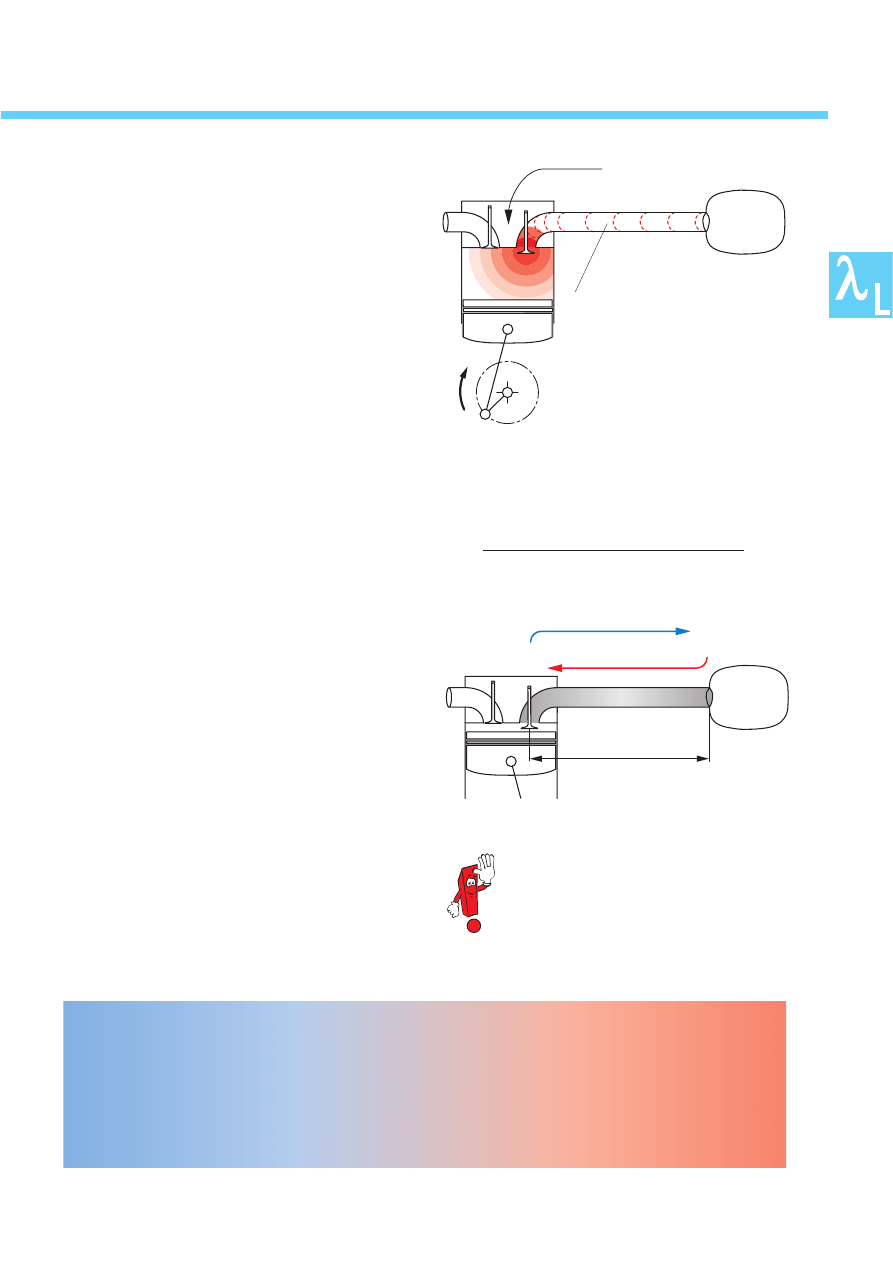
Development of high-pressure wave
Pressure wave
Collector
Resonance pipe
7
This high-pressure wave travels back through the
resonance pipe and pushes the air mass past the
still-open inlet valve into the cylinder.
This continues until the pressure before the inlet
valve and the pressure in the cylinder are equal.
The engine experiences “ram-effect” charging.
The volumetric efficiency (see page 4) reaches
values of about 1.0 and even above.
As a result, when the inlet valve closes, backflow
of the ram-effect charging into the intake pipe is
prevented.
The time t (in milliseconds) required by the low
and high-pressure waves to cover the distance S
from the inlet valve to the collector and back is
always the same because they move at the
speed of sound, v.
But the time period during which the inlet valve is
opened is dependent on engine speed.
As engine speed increases, the period of time
during which the inlet valve is open and air can
flow into the cylinder decreases.
A high-pressure wave returning through a reso-
nance pipe designed for low engine speeds will
run into an inlet valve which has already closed.
“Ram-effect” charging cannot take place.
It is clear that resonance pipes of different
lengths are required for optimal charging at
every engine speed.
The technical compromise is resonance
pipes of different lengths!
Long pipes (torque stage)
for low to
middle engine speeds.
Short pipes (power stage)
for high engine
speeds.
Resonance pipes of different lengths can
be opened or closed depending on engine
speed
= variable intake manifold.
s = constant (length of resonance pipe)
v = constant (speed of sound)
t =
The higher the engine speed, the shorter
the resonance pipe length.
212_008
“Ram-effect” charging
Pressure wave
Resonance pipe
s
Low-pressure wave
High-pressure wave
212_009
[ms]
8
The variable intake manifold is designed as an
over-head intake manifold with differing channel
lengths. In addition, the resonance pipe lengths
are specific to the cylinder bank and therefore
averages.
The lengths differ for the VR5 and VR6 engines.
The variable intake manifold of the VR engines
The air channels of the intake ports in the
cylinder head go though the lower intake
manifold part to the resonance pipes in the
upper intake manifold part. Here they branch
into torque and power pipes.
The torque pipes follow a tight curve over the
cylinder head and terminate in the torque
collector.
The power pipes follow a wider curve above
the torque pipes and terminate in the second
collector, the power collector, which is located
over the front part of the torque pipes.
A change-over barrel is inserted in the power
pipes, perpendicular to them. It opens the power
pipes and, consequently, the power collector as
necessary.
A plastic variable intake manifold is planned for
all VR engines.
This is more economical than cast aluminium,
lighter and offers acoustic advantages.
Resonance pipe lengths (mm)
VR5
VR6
Torque pipes
700
770
Power pipes
330
450
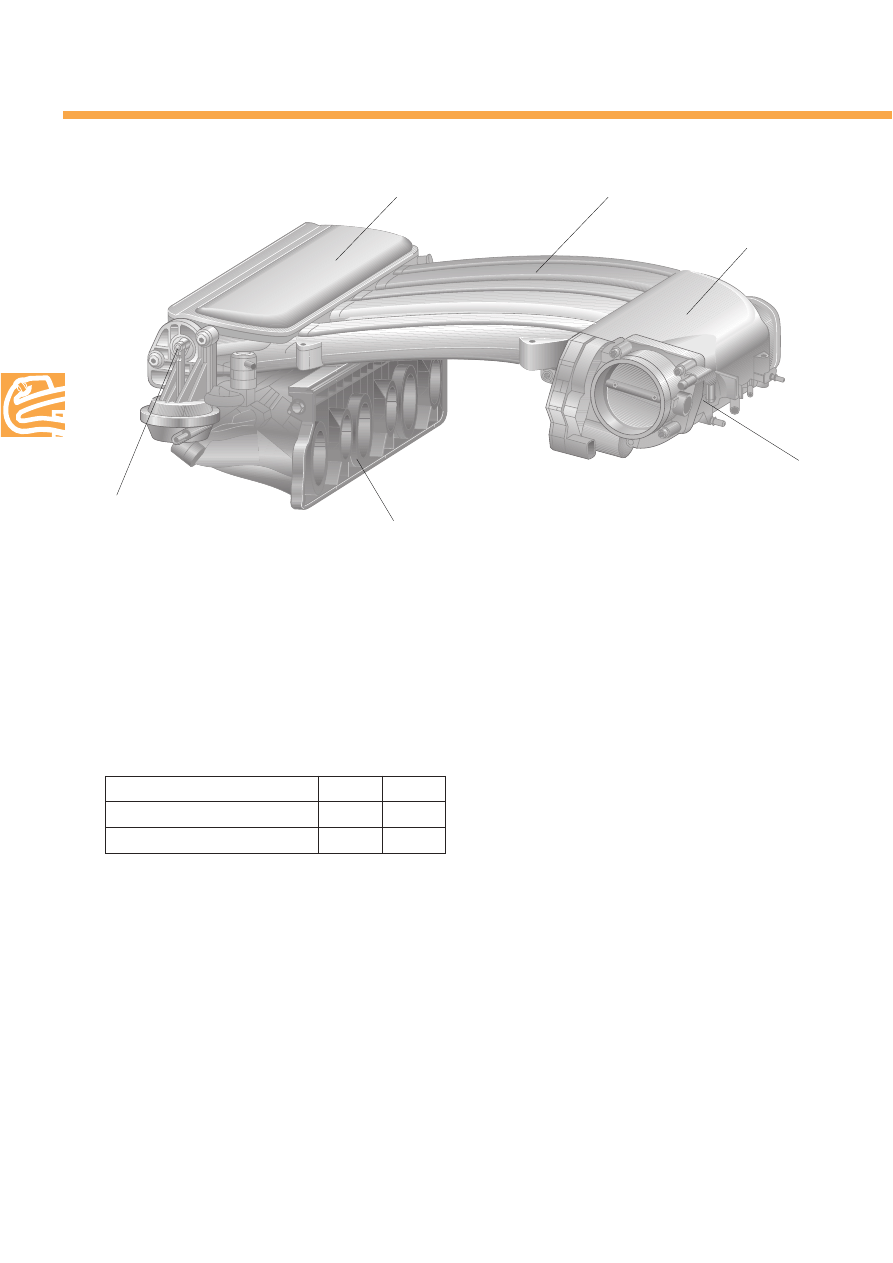
Power collector
VR6 variable intake manifold
Resonance pipes
Torque collector
Throttle valve positioner
Intake manifold,
lower part
Change-over
barrel actuator
212_028
For assembly reasons, the variable intake mani-
fold is divided into an upper and a lower part.
The injectors and fuel rail with pressure regulator
are integrated into the lower intake manifold
part.
The upper intake manifold part contains the
resonance pipes, the power collector, the
change-over barrel with actuator, the torque
collector and the throttle valve positioner, which
is attached to the torque collector.
9
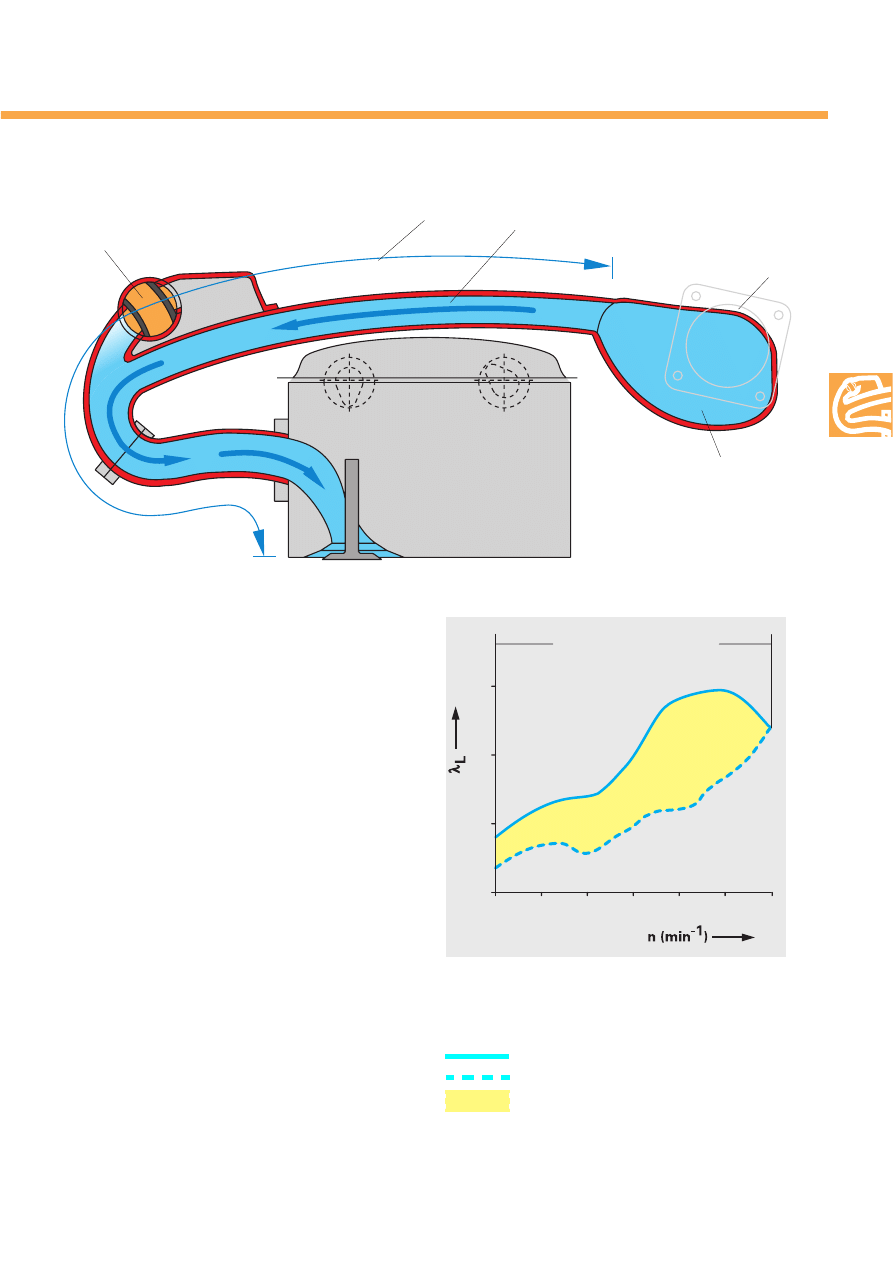
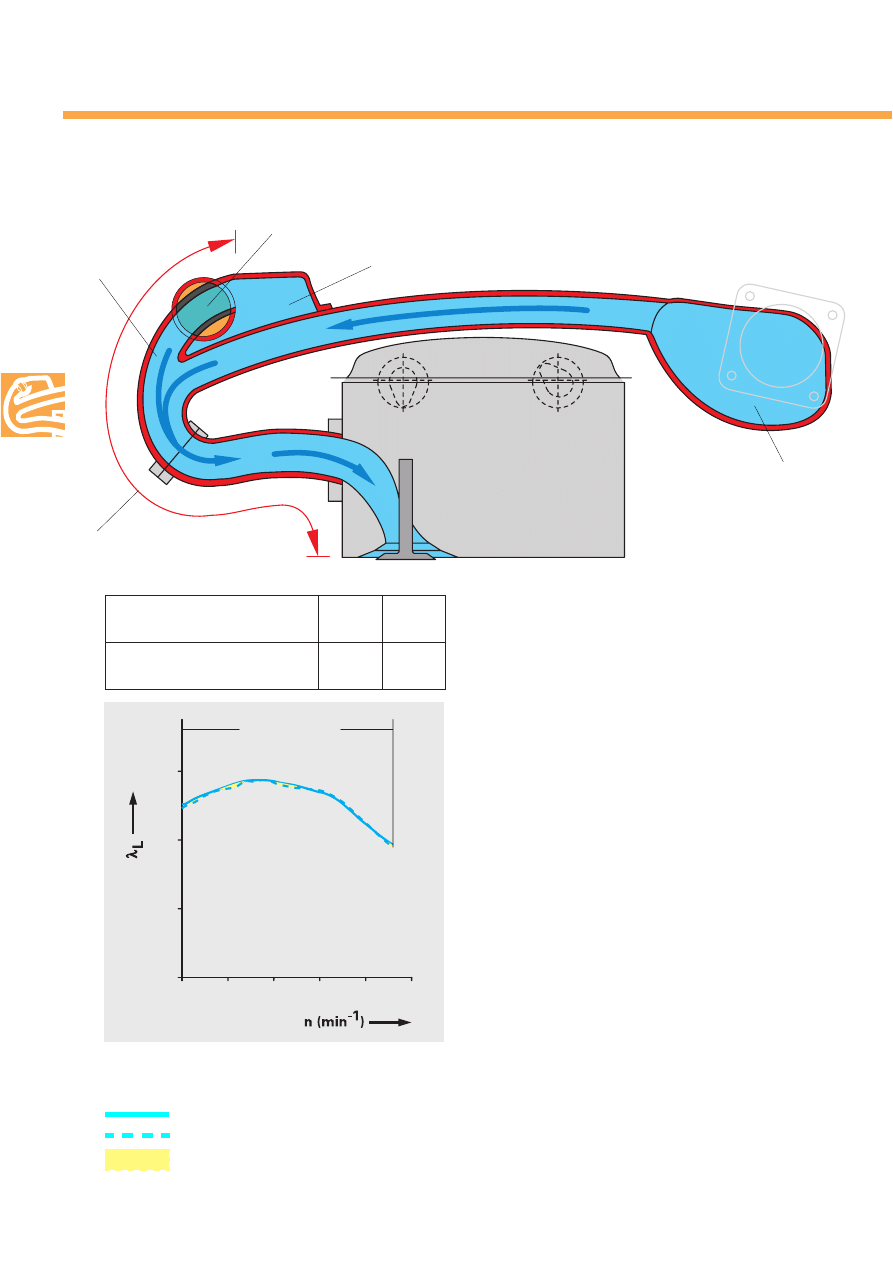
Comparison of volumetric efficiency
with variable intake manifold
without variable intake manifold
improvement in volumetric efficiency
0,8
1000
2000
3000
0,7
0,9
1,0
4000
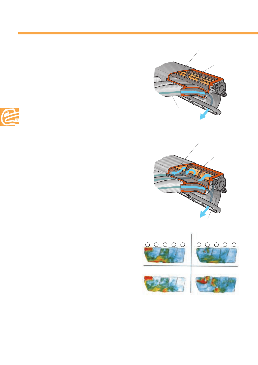
Torque position of VR6 variable intake manifold
The torque position shows air channelling in low
engine speed range.
The change-over barrel has closed the power
pipes.
The cylinder draws air through the long torque
pipes directly from the torque collector.
The effective length of the torque pipes
(= resonance pipe length) is 770 mm.
The result at low and middle engine speeds is
higher volumetric efficiency.
Change-over barrel
in torque position
Torque pipes
Torque collector
Air entrance at throttle
valve control part
Effective length of torque pipes
212_011
212_012
Torque position
(long pipes)
V
o
lumetric efficiency
Engine speed
10
The variable intake manifold of the VR engines
Power position of the VR6 variable intake manifold
The change-over barrel is rotated 90
o
at a
specified engine speed.
This action opens the power pipes and the con-
nection to the power collector, which results in an
effective length of 450 mm for the power pipes.
Air is now supplied from both the torque pipes
and the power pipes.
The power collector is supplied with air via the
torque and power pipes leading to cylinders
which are not drawing air (see also page 14).
The low-pressure wave created at the start of the
intake process is reflected at the end of the
power pipe in the power collector.
Consequently, it returns after a short period to
the inlet valve as a high-pressure wave.
The shortened length of the resonance pipe
produces a high degree of volumetric efficiency
at a high engine speed.
The power position, designed for the power
range, results in slight differences, as expected.
Power pipes
212_013
Change-over barrel in power position
Effective length of
power pipes
Power collector
Torque collector
Change-over to power pipes
at engine speedl
VR5
VR6
rpm
4200
3950
0,8
4000
5000
6000
0,7
0,9
1,0
Power position
(shorter pipes)
Comparison of volumetric efficiency
With variable intake manifold
Without variable intake manifold
Improvement in volumetric efficiency
212_014
11
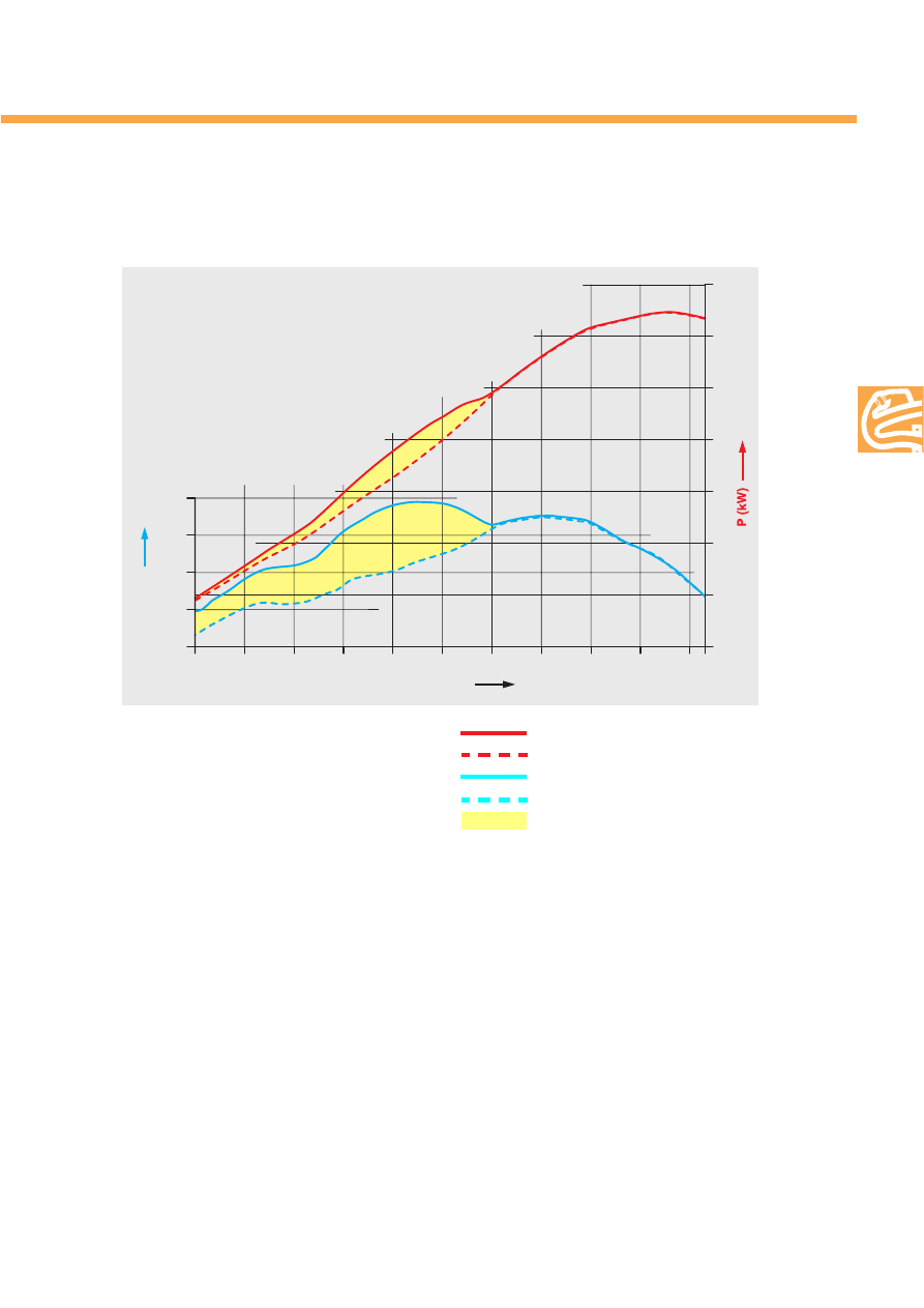
Power and torque of VR6-Motor
with and without variable intake manifold
The gains in power and torque in the low and
middle engine speed ranges made with the new
variable intake manifold on the VR6 engine are
clearly recognisable (the VR5 engine had a
variable intake manifold from the start of pro-
duction).
The high torque permits a more relaxed driving
style in the lower and middle engine speed
ranges as well as the frequent use of higher
gears without loss of pulling power but with low
fuel consumption.
As a result, the change-over barrel is rarely
operated.
Impurities such as dust or oil can lodge in the
gap between the change-over barrel and its
housing, impeding its operation.
To ensure its proper operation, the change-over
concept was extended by an additional change-
over point in the first stage of development.
The change-over barrel is held in the power
position up to about 1,100 rpm and only then
turned to the torque position.
This additional change-over point causes the
change-over barrel to be operated repeatedly,
and impurities cannot lodge on it.
n (min )
-1
M (Nm)
170
1000
2000
3000
4000
5000
6000
190
210
230
250
0
20
40
60
80
100
120
140
212_015
Power
with variable intake manifold
Power
without variable intake manifold
Torque
with variable intake manifold
Torque
without variable intake manifold
Gain in power and torque
M = Torque
P = Power
n = Engine speed (rpm)
12
The variable intake manifold of the VR engines
A further development –
the load-dependent change-over
concept
According to this concept, the change-over
points for turning the change-over barrel are
determined according to load.
Below full load, the change-over barrel is
mapped to be in the power position.
This is also the rest position when the engine is
stopped.
To achieve maximum filling of the cylinder, it is
not turned to the torque position until the engine
is close to full load.
Because the resonance pipes are de-tuned, the
resonance-charging effect in the partial load
range is reduced.
For the same planned power, the engine can be
operated with a lower load.
The gas dynamics in the intake manifold are
reduced, consequently reducing the charging
of the combustion chamber.
Patent has been applied for on this
equipment!
Advantages!
Lower fuel consumption
Smoother combustion
Improved acoustics
n (min )
-1
M (Nm)
1000
2000
3000
4000
5000
6000
7000
0
50
100
150
200
250
212_016
Change-over points of VR5 2V engine as example
Full load
Change-over barrel
in torque position
Switching point -
Turn from power to torque position
Engine speed
To
rque
13
M (Nm)
n (min )
-1
2000
125
4000
6000
150
175
200
225
0,27 mm
0,42 mm
0,58 mm
0,72 mm
212_018
Air gap
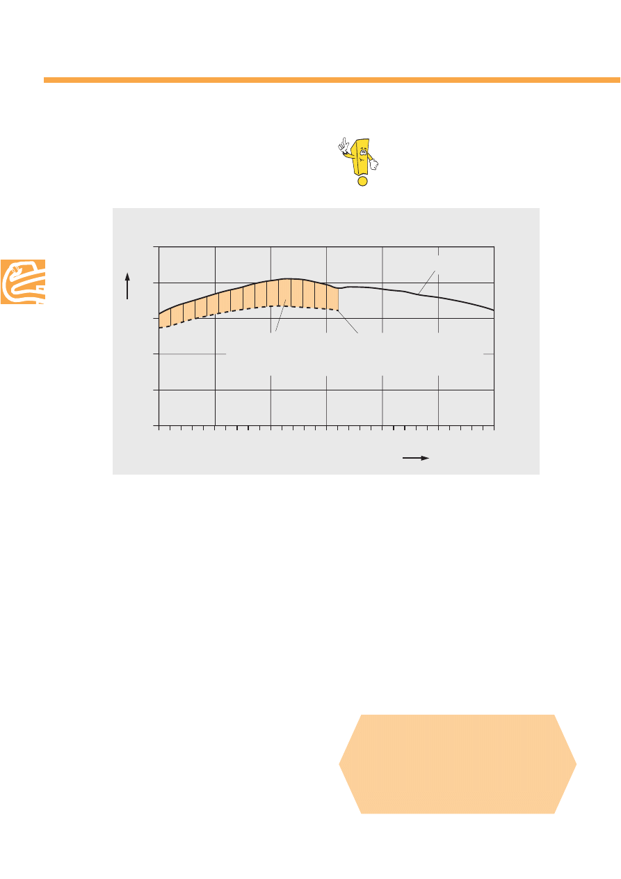
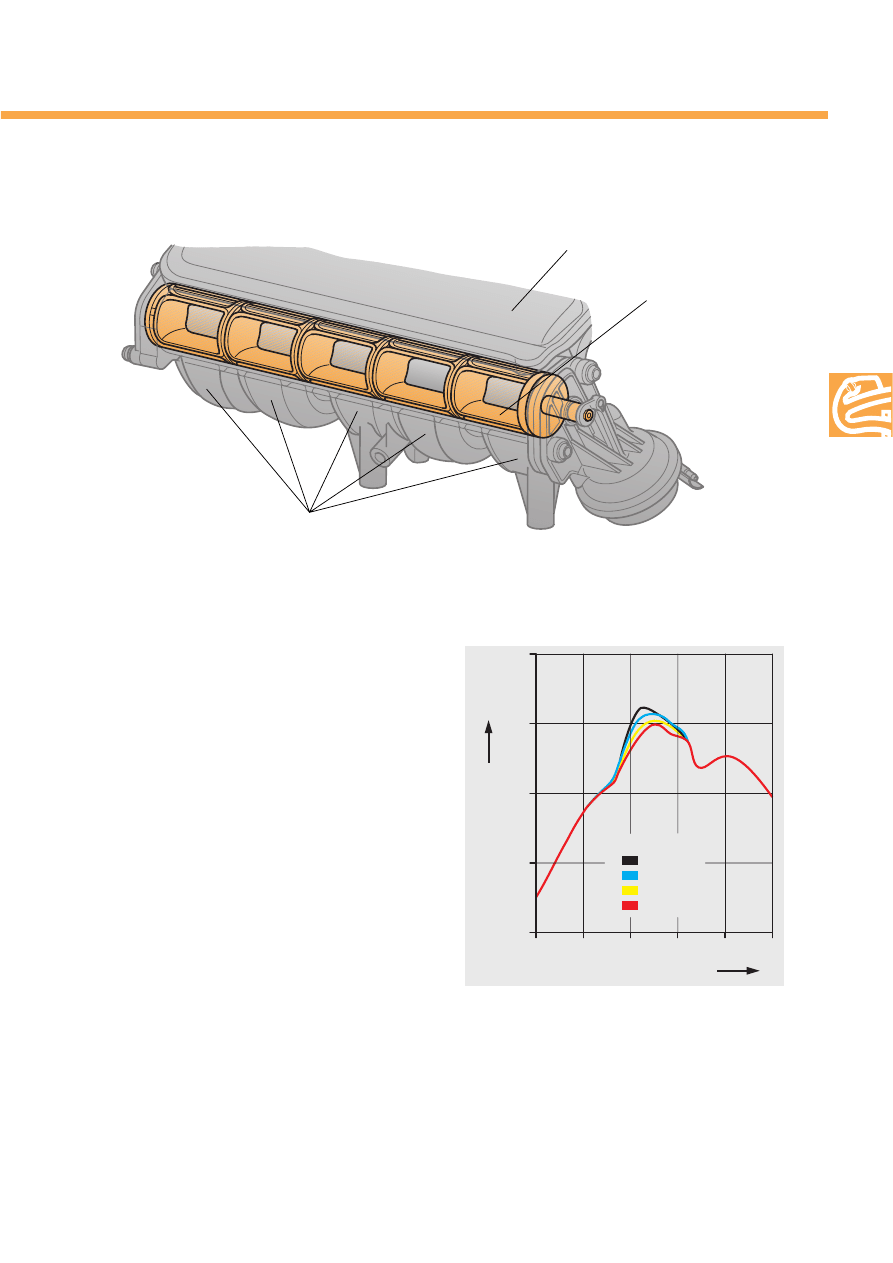
The switch mechanism located in the upper
intake manifold part works on the change-over
barrel principle.
The change-over barrel has a separate passage
for each power pipe.
In the power position, the passages become a
part of the power pipe.
The change-over barrel is made of plastic and is
elastically supported.
Differing expansion coefficients of intake mani-
fold and change-over barrel, and security
against seizing place high demands on the relia-
bility of the process.
A radial tolerance between the change-over
barrel to the power collector is necessary to
ensure its operation but must not be too great.
Even minimal air gaps lead to a significant
reduction in achieved torque. This reduction is
caused by the reflected waves travelling bet-
ween individual pipes to the power collector,
resulting in the loss of energy.
The influence of the air gap of the change-over
collector on torque in the VR5 engine.
Maximum torque shifts to a higher rpm range.
In the power range (open power pipes), the air
gap cannot have any significance.
Power airbox and change-over barrel
Variable intake manifold on VR5engine with change-over barrel in torque position
212_017
Intake pipes (power pipes)
Change-over barrel
Power collector
14
The variable intake manifold of the VR engines
Filling the power collector
A reminder:
Closed change-over barrel = torque position
Each cylinder receives its charge of air directly
from the torque collector through its respective
torque pipe.
The power collector is closed for all cylinders.
It has no influence on the volumetric efficiency
of the cylinder.
The power collector is not filled either.
Example of current progression in collector.
At a crankshaft angle of 555
o
, the current moves from No. 3
cylinder 3 to No. 1 cylinder.
Beginning at about crankshaft angle 605
o
, the intake phase
of No. 2 cylinder leads to a reversal of the current direction.
Decimal points represented by commas in graphic.
212_003
Power collector
Change-over barrel closed
Torque pipe
212_002
Power pipe
Open change-over barrel = power position
With its passages (one per pipe) open, the
change-over barrel connects the power pipe to
the power collector.
The cylinder which is drawing at the moment
receives its air primarily from the power pipe but
also through its torque pipe.
In the power position, the power collector is filled
by the flowing volume of air which is reflected
from the closed inlet valves of the cylinders which
are not drawing air.
Air currents develop high velocities in the collec-
tors.
Due to the over-all manifold design, a direct
connection between torque and power collectors
is not necessary for filling the power collector.
Power collector
Change-over barrel open
212_021
555
o
CA
575
o
CA
605
o
CA
635
o
CA
1
5
3
2
4
1
5
3
2
4
cylinder
cylinder
15
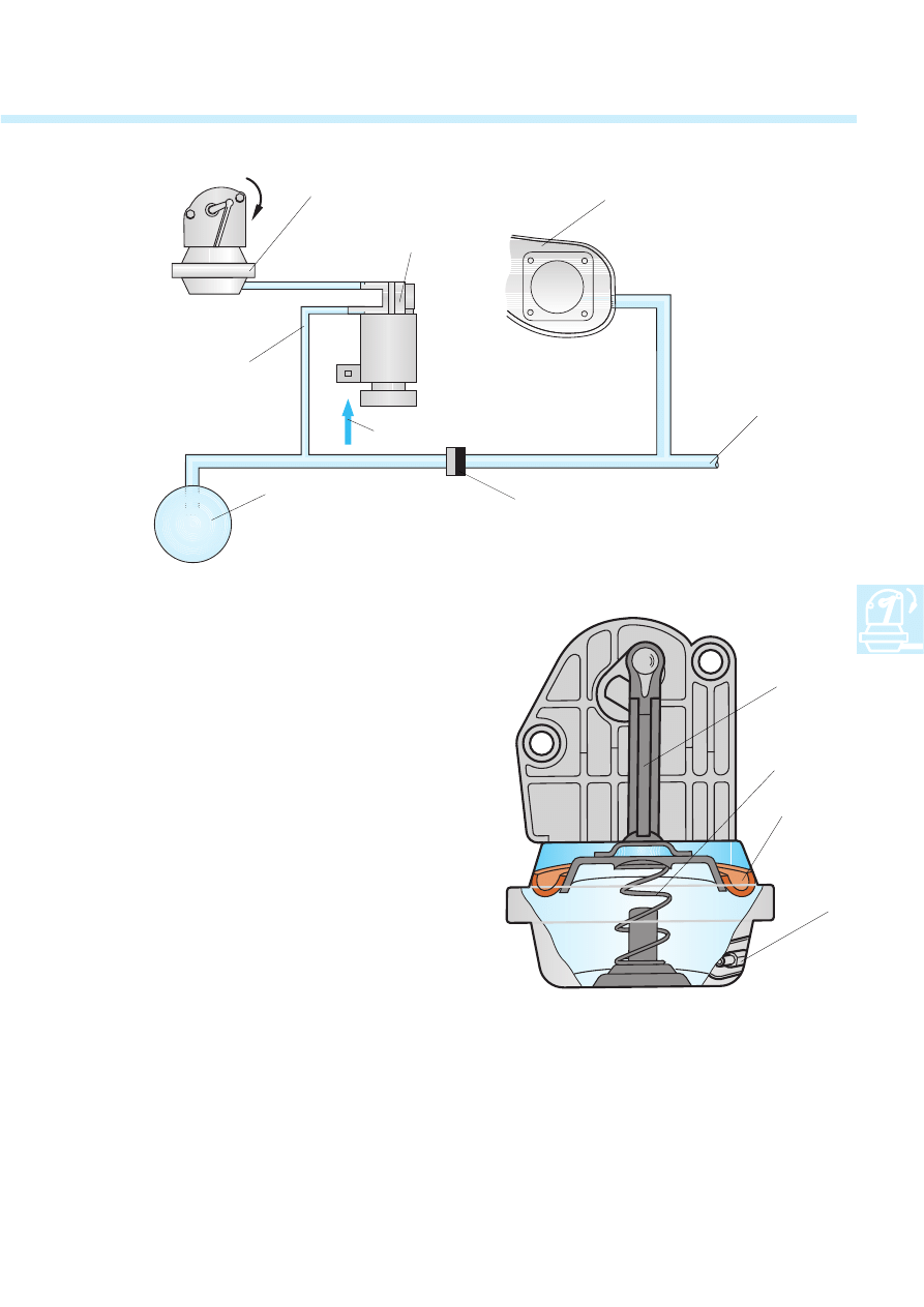
The tension of the compression spring is over-
come and the membrane together with the con-
necting rod is pulled downwards.
The change-over barrel is rotated 90
o
.
The torque position comes into effect.
Intake manifold change-over
Changing pipes is done pneumatically with
vacuum.
The pneumatic actuation is controlled by the
engine control unit via the intake manifold
change-over valve N156 (solenoid valve).
The vacuum is taken from the manifold torque
collector.
Vacuum is stored in the vacuum reservoir and a
check valve prevents the release of the vacuum.
The change-over barrel is in the power position,
that is, the intake path is short, when the engine
is not running or running at idle.
It is held in this position by a compression spring.
The intake manifold change-over valve blocks
the vacuum to the vacuum unit.
When the intake manifold change-over valve is
actuated, vacuum is released to the vacuum unit.
212_019
Pneumatic switching
Vacuum line
To other
consumers
Manifold/
torque collector
Intake manifold
change-over valve N156
Vacuum unit
Vacuum reservoir
Check valve
Actuation by engine control unit
Operating rod
Membrane
Connection from
solenoid valve line
Vacuum unit
212_023
Compression spring
16
Intake manifold change-over
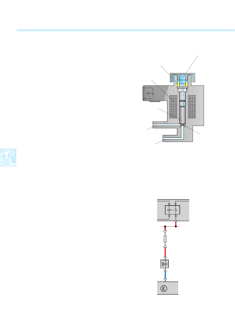
Intake manifold change-over valve
N156
Function
The intake manifold change-over valve is a sole-
noid valve.
It is controlled by the engine control unit and
depends on load and engine speed.
Atmospheric pressure acts on the magnet which
forms the valve.
Together with the rubber valve plate, it blocks
the vacuum line to the vacuum unit.
When the solenoid is actuated, the magnet is
raised and the vacuum line is opened.
A foamed plastic filter at the entrance for
atmospheric air pressure prevents the penetra-
tion of dirt particles which could impede the
movement of the valve.
Emergency operation
If there is no signal, the vacuum line to the
vacuum unit remains closed. The shorter intake
path in the variable intake manifold remains
open. A substitute function is not planned.
Self-diagnosis
Self-diagnosis is performed with the following
functions:
02 - Interrogate fault memory
Short to earth
Short to positive
Open circuit
03 - Final control diagnosis
Electrical circuits
J17
Fuel pump relay
J220 Engine control unit
N156 Intake manifold change-over valve
S
Fuse
212_001
212_022
Atmospheric pressure
Foamed plastic filter
Magnetic coil
Magnet
(Valve)
Valve plate
From vacuum reservoir
To vacuum unit
S
N156
J220
J17
17
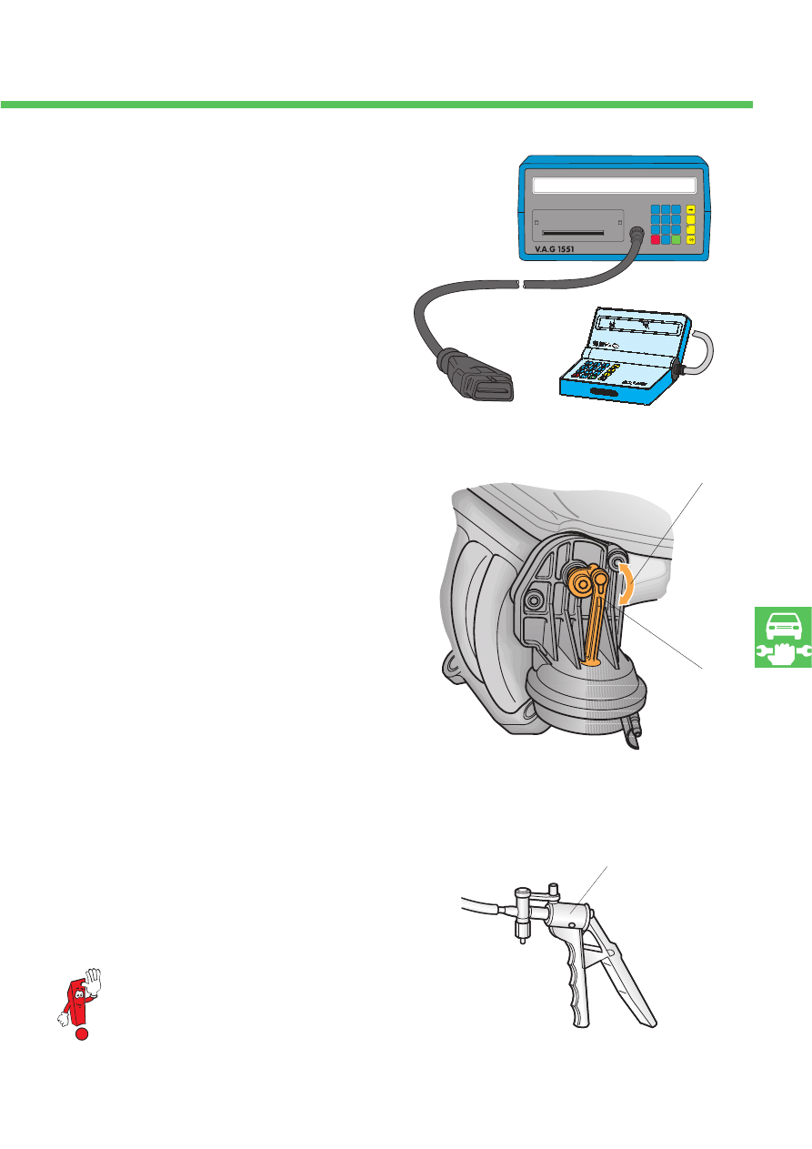
Service
The variable intake manifold and its actuator are
service-free.
If the engine is shown to have power deficits, the
operation of the variable intake manifold is easy
to test:
– Via self-diagnosis
The intake manifold change-over valve data
is available under the functions 02 - Read out
fault memory and 03 - Final control diagno-
sis.
– Visual inspection of the 90
o
rotation at the
vacuum unit with the help of the engine
speed.
Knowledge of the operation of the variable
intake manifold helps as well.
Important:
When the engine is not running or running at
idle, the change-over barrel is in position for
the shorter intake path, or power position.
Bear in mind:
Differing change-over concepts
= with additional change-over point; up to
1100 rpm in power position, then change-over
to torque position and at 4200 rpm back to
power position.
= load dependent change-over; with throttle
burst under full load below 4000 rpm,
change-over to torque position.
Checking change-over movement
with vacuum using hand vacuum pump V.A.G
1390.
Please refer to the current workshop
manual for exact instructions for all
tests.
212_027
1
4
7
C
2
5
8
0
3
6
9
Q
V.A.G - EIGENDIAGNOSE
HELP
01 - Motorelektronik
HELP
203_026
212_025
Idling/power
positions
90
o
change-over movement
V.A.G 1390

?
18
Test you knowledge
Which answers are correct?
Sometimes just one.
But sometimes several or all answers may be correct!
Fill in the blanks: .............................. .
1.
The “ram-effect charging” of a petrol engine is determined by the engine speed
and the period that the inlet valve is open.
The first principle can be derived from this:
The .................... the engine speed, the .................... the intake pipe length.
2.
Consequently, the first principle is the basis for the concept of a variable change-over
intake manifold
with .................... intake pipes in the low engine speed range
for .................... ..................... .
with .................... intake pipes in the high engine speed range
for power production.
3.
The volumetric efficiency VE makes a statement
A.
about the fuel/air mixture.
B.
about the fuel/oxygen mixture.
C.
about air supply with ratio of the actual air mass in the cylinder to the
theoretical air mass in the cylinder.
4.
One characteristic of the variable intake manifold on the VR engines is the change-over barrel.
It
A.
lies transverse before all torque pipes.
B.
opens the path to the torque pipes when it is actuated.
C.
creates with its passages the connection from the power pipes to the power collector
when actuated.
212_024

?
19
5.
What is joined directly to the torque collector?
A.
the torque pipes
B.
the power pipes
C.
special pipes to supply the power pipes
6.
The high torque achieved with the variable intake manifold permits frequent use of upper gears in
low and middle engine speed ranges without loss of pulling power.
A.
This improves the service life of the change-over barrel because it is operated less.
B.
This is bad for the operation of the change-over barrel because it is operated less.
C.
Frequent change-over motion is good for the self-cleaning of the change-over barrel.
Therefore the change-over concept was extended by an additional change-over point
in the low engine speed range.
7.
The change-over barrel is .................... supported.
It is operated .................... .
The .................... influences torque.
8.
The actuator for operating the change-over barrel is a vacuum unit.
A.
A compression spring in the vacuum unit holds the change-over barrel in the power position.
B.
A compression spring in the vacuum unit holds the change-over barrel in the torque position.
C.
Actuating the vacuum unit switches the manifold to the power position.
Answers
1. higher, shor
ter; 2. long, high t
orque pr
oduction, shor
t; 3. C; 4. C; 5. A; 6. B, C;
7. elastically
, pneumatically, r
adial air gap; 8. A
212
Service.
For internal use only© VOLKSWAGEN AG, Wolfsburg
All rights reserved, subject to technical change without notice
740.2810.31.20 technical status 12/98
❀
This paper was made with chlorine-free
bleached cellulose.
Wyszukiwarka
Podobne podstrony:
SSP 212 Schaltsaugrohre der VR Motoren
SSP 212 DE
SSP 263 DE Der Polo Modelljahr 2002
SSP 024 Skoda Octavia Der CAN Datenbus Konstruktion und Funktion
PLL in der Schaltungssimulation Berechnungsgrundlagen des Nachlaufsynchronisation
Gegenstand der Syntax
60 Rolle der Landeskunde im FSU
AP 212 Fairey Swordfish MKS I IV
Zertifikat Deutsch der schnelle Weg S 29
(8) C 212??ntros Ltd
dos lid fun der goldener pawe c moll pfte vni vla vc vox
Christie, Agatha 23 Der Ball spielende Hund
Motoredutor A0 id 308263 Nieznany
alfik 212 4
Impregnaty trojfunkcyjne id 212 Nieznany
Glottodydaktyka Grundlagen der Nieznany
Der Erlkoenig ( Król Olch )
julis haben angst vor der piratenpartei 2009
więcej podobnych podstron