
28-1
Motronic Multiport Fuel
Injection (MFI) and ignition
system
Ignition system, repairing
Notes:
Only components relating to the ignition system
are covered in this repair group. For other
components of the injection and ignition system
Repair Group 24.
The Motronic Engine Control Module (J220) for
the ignition and fuel injection system is
equipped with Diagnostic Trouble Code (DTC)
memory.
Components marked with an asterisk (*) are
checked by the On Board Diagnostic (OBD)
program.
Before repairing or troubleshooting, check
Diagnostic Trouble Code (DTC) Memory,
Repair Group 01.
Safety rules
page 28-5

Spark plugs, technical data
page 28-7
28-2
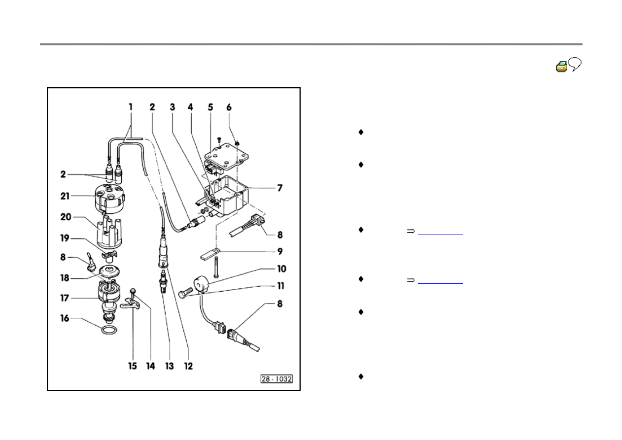
Ignition system, components
1 - Ignition wire
Check for continuity
2 - Interference suppression connector
Resistance 600 to 1400 Ohms
3 - Terminal 1
4 - Terminal 15
5 - Ignition Coil Power Output Stage (N157)*
Checking
page 28-15
6 - 10 Nm (7 ft lb)
7 - Ignition coil (N152)
Checking
page 28-14
8 - Connector
3-pin
9 - Ground (GND) strap
10 - Knock Sensor 1 (G61)*
11 - 20 Nm (15 ft lb)
Incorrect tightening torque affects function of Knock
Sensor
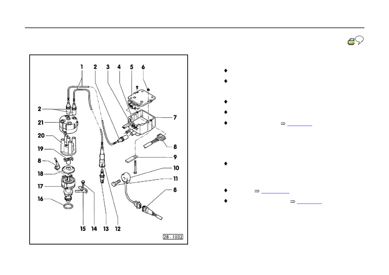
28-3
12 - Spark plug connector
Resistance 4000 to 6000 Ohms
Remove and install with VW 3277
13 - Spark plug
Tightening torque 30 Nm (22 ft lb)
Remove and install with 3122B
Type and spark gap
page 28-7
14 - 25 Nm (18 ft lb)
15 - Clamp
16 - O-ring
Always replace
17 - Ignition Distributor with Camshaft Position (CMP)
Sensor (G40)*
Checking
page 28-13
Removing and installing
page 28-8
18 - Dust cap
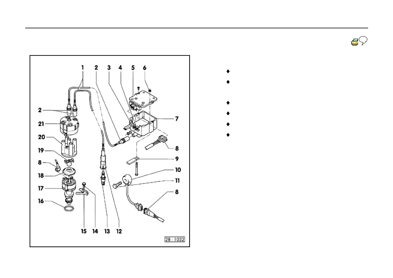
28-4
19 - Rotor for Ignition Distributor
Identification: R1
Resistance: 600 to 1400 Ohms
20 - Distributor cap
Check for cracks, traces of current leaks
Check for wear on contacts
Clean before installing
Check carbon brushes for wear and freedom of
movement
21 - Interference suppression cap

28-5
Safety rules
CAUTION!
To prevent personal injury or damage to
sensitive electrical components:
Switch ignition OFF before connecting or
disconnecting components or test
equipment.
Connect or disconnect Battery only with
ignition switched OFF to prevent damage to
the Engine Control Module (ECM).
If engine must be cranked but not started (for
compression testing, etc.) disconnect
Ignition Coil Power Output Stage (N157).
DO NOT use battery booster for longer than
one minute and DO NOT exceed 16.5 volts
(v).
DO NOT wash engine unless ignition is
switched OFF.
Switch ignition OFF when arc or spot

welding.
Before towing vehicles with suspected
malfunctioning ignition system, disconnect
terminal 1 (green) on Ignition Coil (N152).
When installing noise suppressors, ONLY
use 1000 Ohm for high tension wires and
5000 Ohm for spark plug connectors
DO NOT replace distributor rotor marked R1
with different type.
If vehicle is heated (paint booth), DO NOT
start engine until cooled to room
temperature.

28-6
Note:
A variety of electrical connectors are used on this
vehicle. Always use VW 1594 adaptor kit to
connect test instruments to these connectors.
CAUTION!
Before disconnecting a Battery, ALWAYS ask
for the correct radio activation code (vehicles
equipped with anti-theft radio).
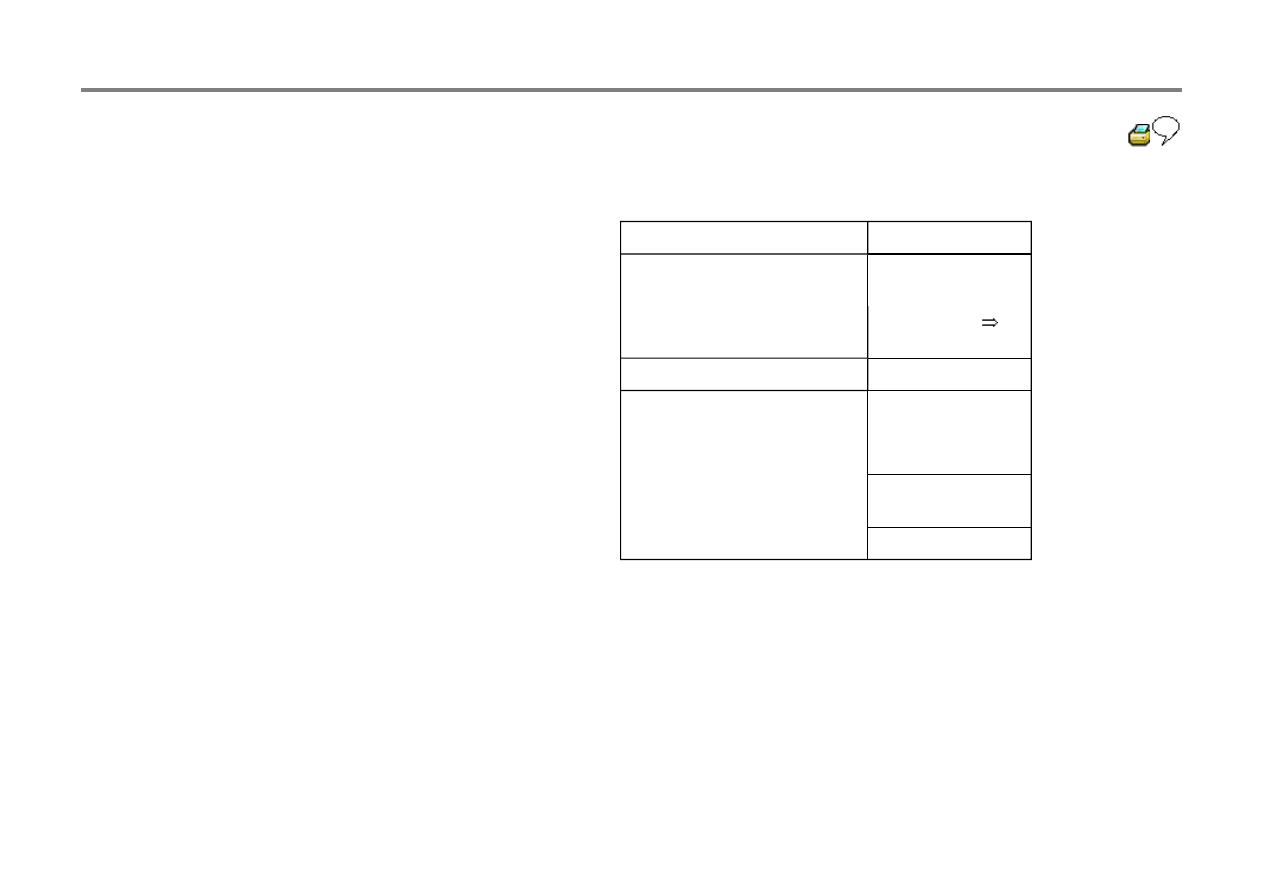
28-7
Spark plugs, technical data
Engine code
ABA
Ignition timing
Cannot be
adjusted
Idle speed
Checking
Repair Group 24
Firing order
1-3-4-2
Spark plugs (remove and
install using tool 3122B)
Bosch FR 8 DS
Part number
101 000 044 AA
Electrode gap
0.6 mm (0.024)
maximum
Tightening torque
30 Nm (22 ft lb)
28-8
Ignition distributor, removing/installing
Note:
For injection timing and knock regulation, the
Motronic Engine Control Module (J220) needs
the TDC cylinder 1 signal from the Camshaft
Position Sensor (G40).
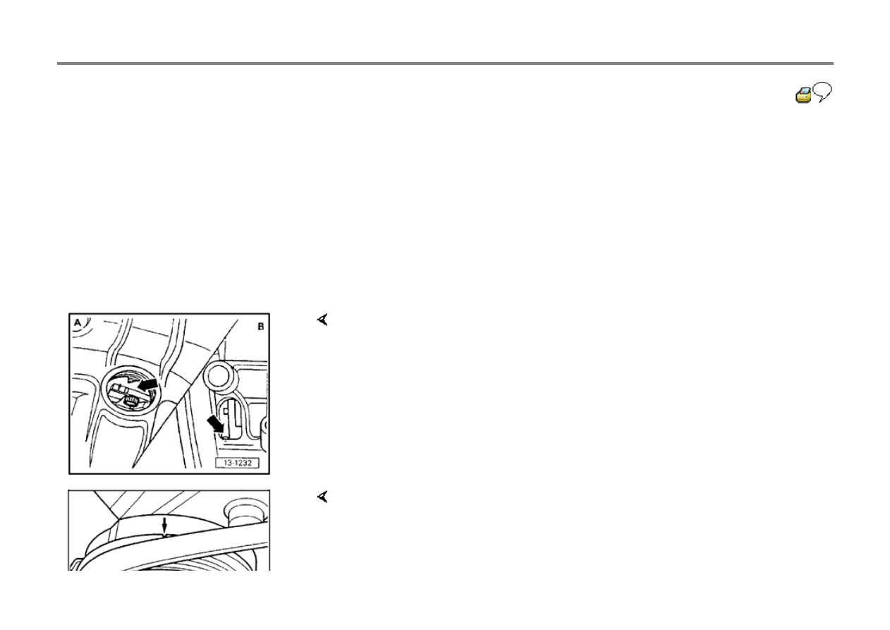
TDC cylinder 1, checking
Engine installed:
Engine removed:
- Move flywheel (-A-) or drive plate (-B-) to cylinder 1 TDC marking -arrow-.
- Set vibration damper to cylinder 1 TDC marking -arrow-.
28-9
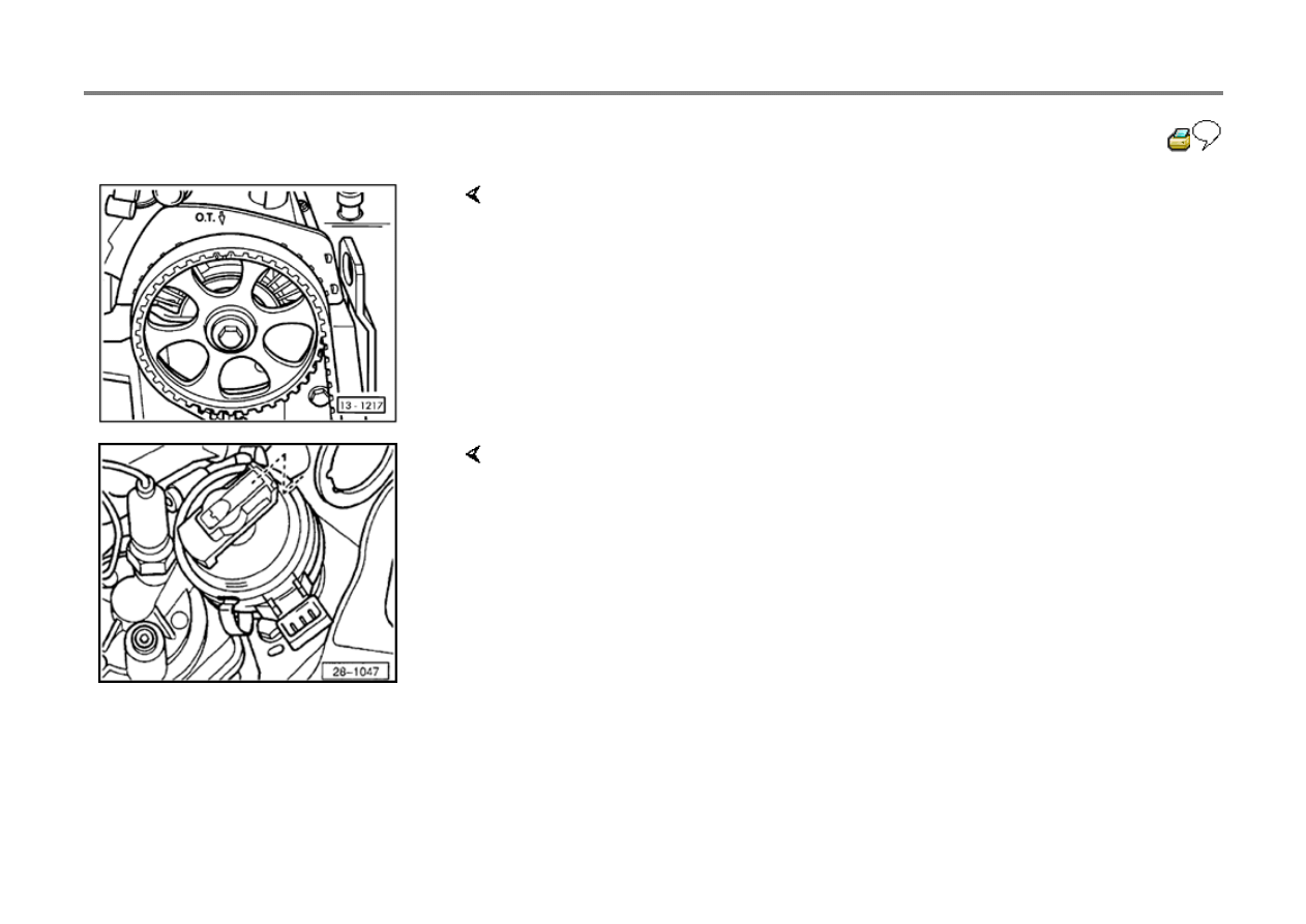
- Marking on camshaft drive belt sprocket must line up with marking on toothed
belt cover.
- Rotor must line up with mark on distributor housing or notch in rim of Camshaft
Position Sensor dust cover.
28-10
Removing
Crankshaft and camshaft in cylinder 1 TDC
position
- Remove distributor.
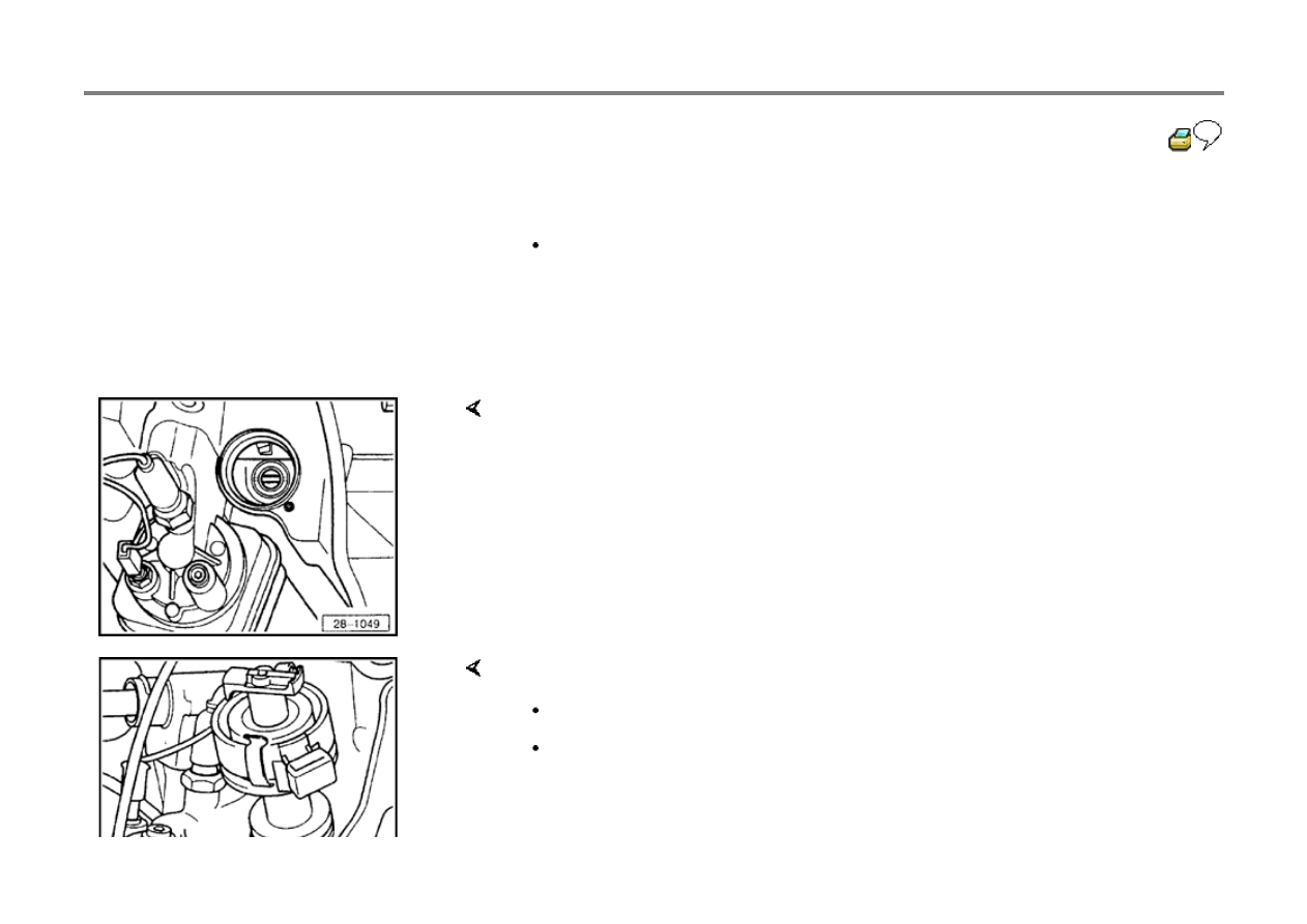
Installing
- Before installing the ignition distributor, position slot on oil pump shaft parallel to
crankshaft.
- Install Ignition Distributor.
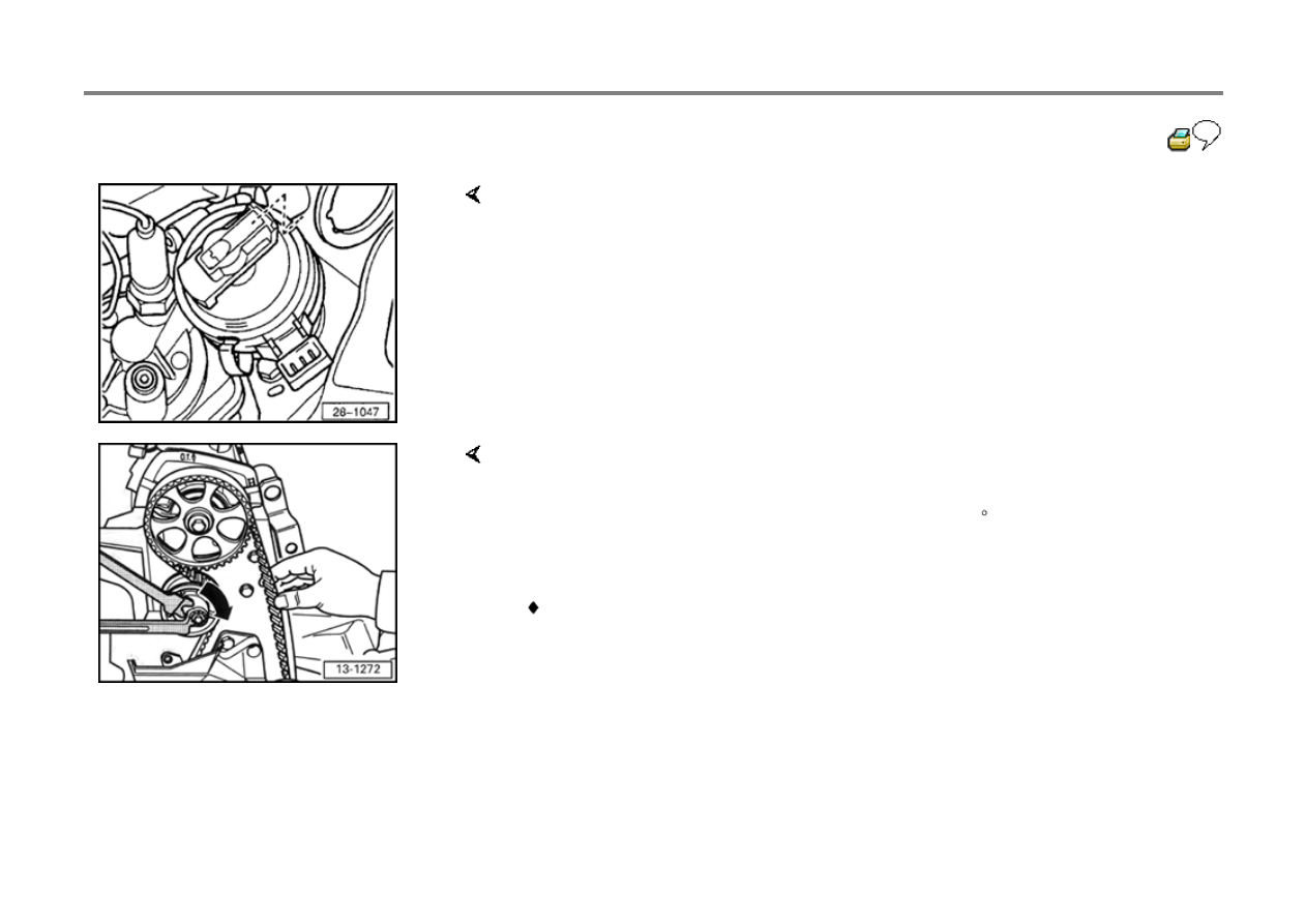
To remove, hold distributor rotor as shown.
Pins on Ignition Distributor must point toward hold for mounting screw -arrow-.
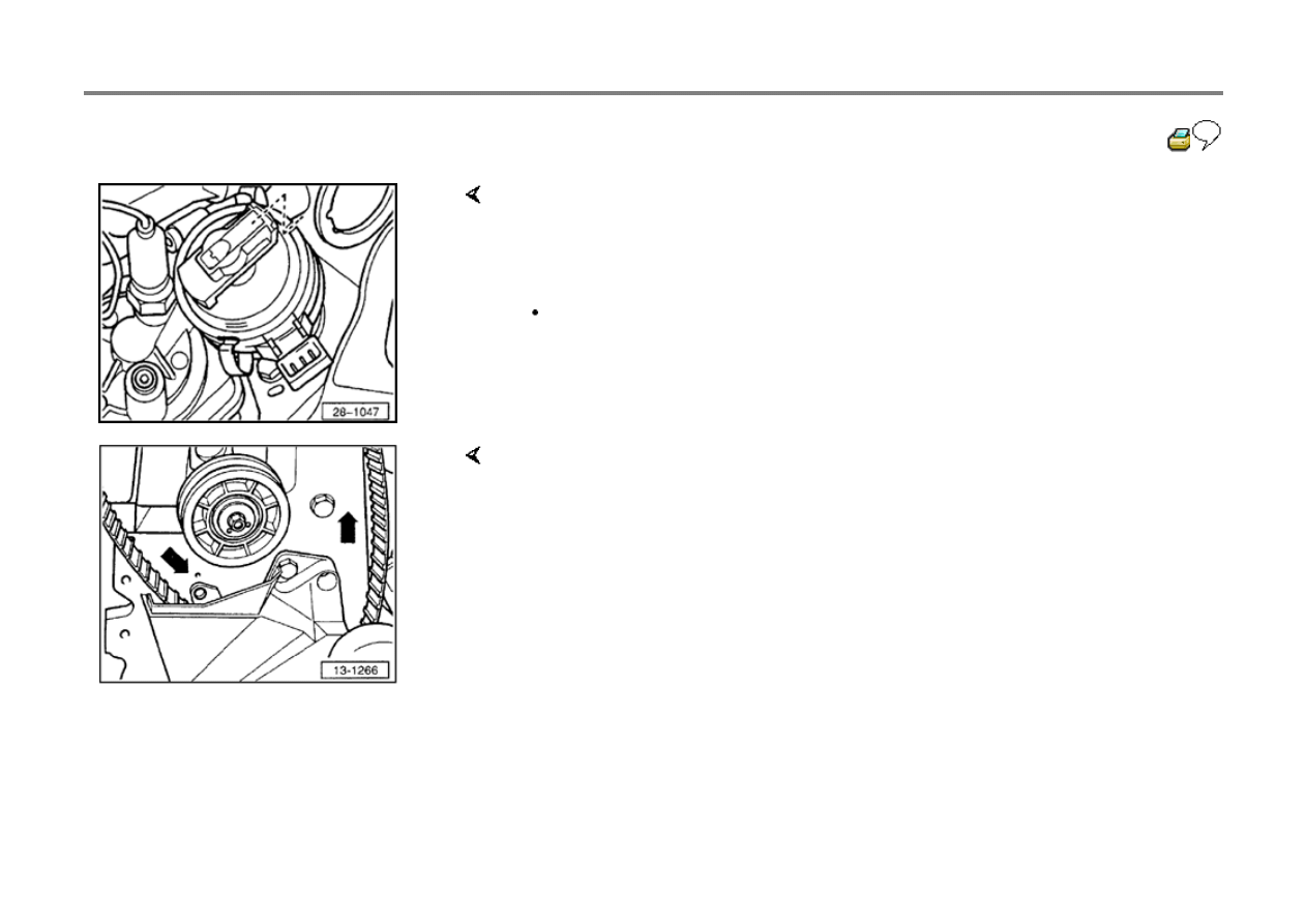
28-11
If markings do not match:
- With the Ignition Distributor installed, marking on housing must line up with
marking on distributor rotor or with notch on rim of dust cover for Camshaft
Position Sensor.
- Tighten mounting screw for Ignition Distributor.
Tightening torque: 25 Nm (18 ft lb)
- Loosen belt tensioner and remove drive belt from camshaft sprocket.
- Turn intermediate shaft sprocket with drive belt in direction of arrows until
marking on distributor rotor lines up with marking for cylinder 1 on distributor
housing (drive belt slips over crankshaft drive belt sprocket).
28-12
Note:
For easier installation of drive belt, only tighten belt tensioner nut approx. one turn.
- Marking on Ignition Distributor must line up with marking on distributor rotor or
with notch on rim of dust cover for Camshaft Position Sensor.
- Position drive belt on pulley and camshaft drive belt sprocket.
- Tighten drive belt by turning belt tensioner in direction of arrow with V159
spanner.
- Drive belt is correctly tensioned if it can be twisted 90 with thumb and
forefinger halfway between camshaft and intermediate shaft sprockets.
- Tighten nut on belt tensioner.
Tightening torque: 45 Nm (33 ft lb)
- Rotate crankshaft two full revolutions and re-check adjustment.
- Check markings on Ignition Distributor and rotor.
- Install upper part of belt guard.
- Clean Ignition Distributor cap and check for cracks before installing.
28-13
Camshaft Position Sensor, checking
Camshaft Position Sensor malfunctions are
recognized by On Board Diagnostic (OBD).
- Carry out electrical testing, test step 21,
Repair Group 01
Specified values:
If OK:
If NOT OK:
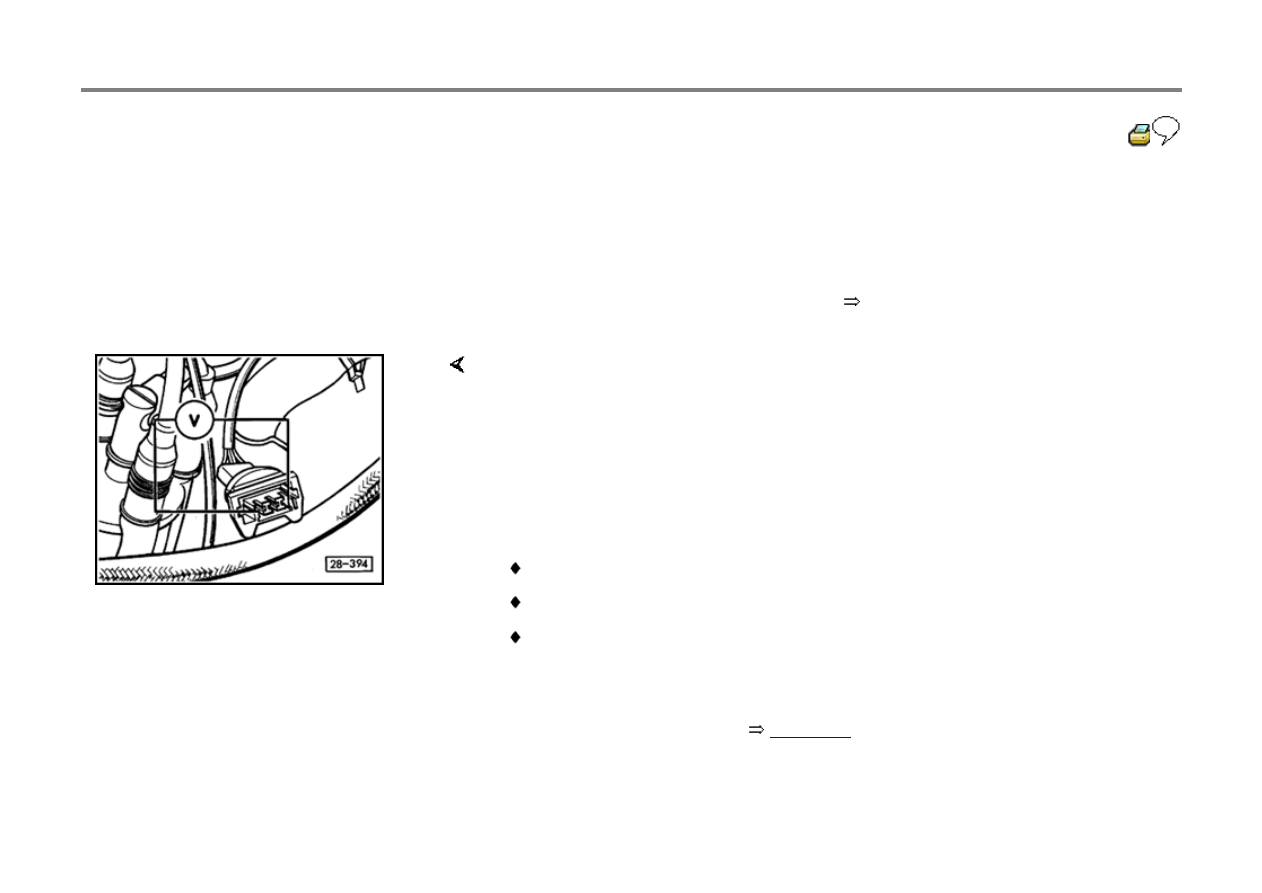
- Disconnect harness connector on Camshaft Position Sensor at Ignition
Distributor.
- Connect Fluke 83 multimeter with adapter cables from VW 1594 to measure
voltage across outer terminals of connector.
- Switch ignition ON.
Up to 10.93 production, 49-states: 10 Volts min.
Up to 10.93 production, California: 5 Volts min.
From 10.93 production, all vehicles: 5 Volts min.
- Replace Ignition Distributor,
page 28-8
.

- Replace Motronic Engine Control Module (J220),
Repair Group 24
28-14
Ignition coil, checking
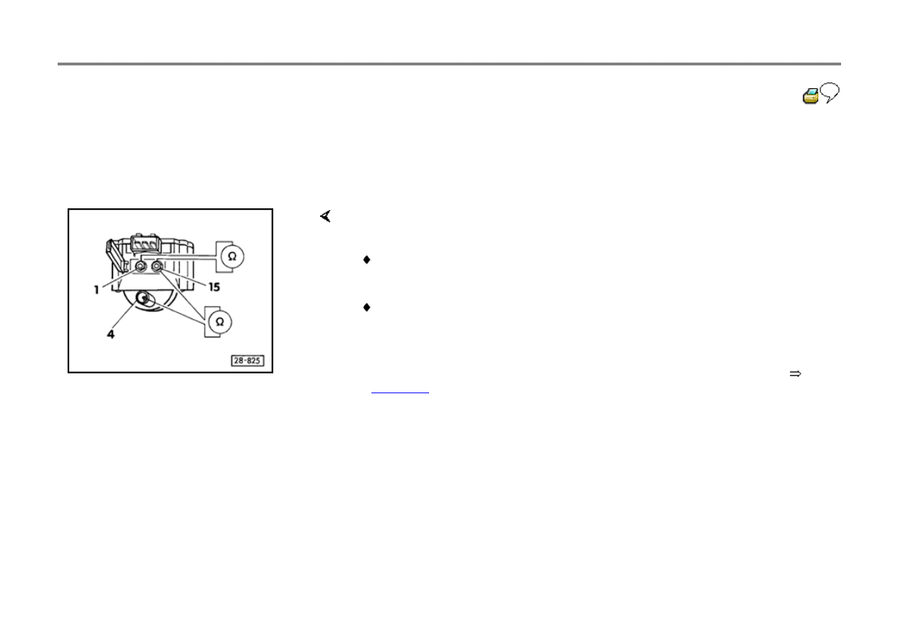
- Disconnect harness connector and ignition wire
from Ignition Coil (N152).
If NOT OK:
- Check primary resistance between terminals -1- and -15- using Fluke 83
multimeter (or equivalent).
Specified value: 0.5 to 0.7 Ohms.
- Check secondary resistance between terminals -4- and -15-.
Specified value: 3000 to 4000 Ohms
- Remove Ignition Coil and disconnect Ignition Power Output Stage (N157)
page 28-2
, item 5.
- Repeat test.
28-15
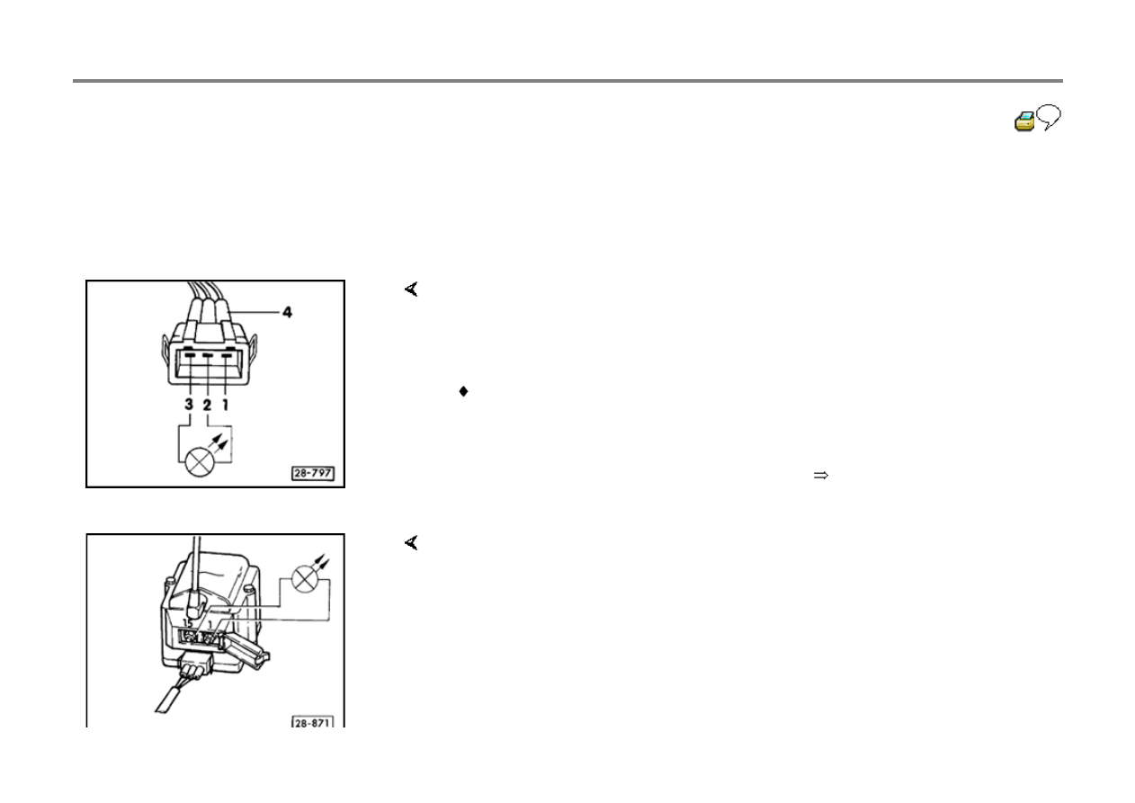
Ignition Coil Power Output Stage,
checking
Requirements
Camshaft Position Sensor (G40) OK
Engine Speed (RPM) Sensor (G28) OK
Electrical testing, test step 22 OK, checking
Repair Group 01
Ignition Coil (N152) OK
Voltage supply, checking
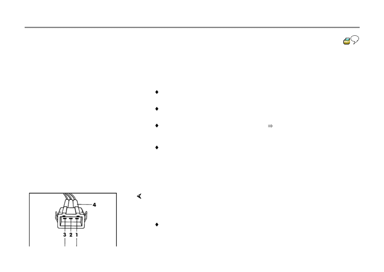
- Disconnect ignition wire and 3-pin connector
from Ignition Coil (N152).
- Connect Fluke 83 multimeter with adapter cables from VW 1594 to measure
voltage at terminals -1- and -3- of disconnected connector.
- Switch ignition ON.
Specified value: Battery Positive Voltage (B+)
- Switch ignition OFF.
28-16
Control, checking
- Disconnect harness connectors from the Fuel
Injector for cylinders 1 and 4 and remove fuse
18 (S18).
If NO:
- Connect US 1115 LED tester to connector terminals -2- and -3- using adapter
cables from VW 1594 adaptor kit and VW 1594/15.
- Operate Starter and check ignition signal from Motronic Engine Control Module
(ECM).
LED should flicker
- Replace Motronic Engine Control Module J220,
Repair Group 24
- Connect 3-pin connector and ignition wire on Ignition Coil.
WARNING!
During the following test DO NOT touch the Ignition Coil or test leads
terminals.
- Connect LED tester with adapter cables to terminals -1- and -15- on Ignition Coil.

28-17
- Operate Starter.
LED should flicker
If NO:
- Replace Ignition Coil Power Output Stage.
- Connect connector to Fuel Injectors.
- Reinstall fuse 18 (S18).
Wyszukiwarka
Podobne podstrony:
g3 mfi ign syst aaa 93 95
g3 mfi ign syst aba 96 99
g3 ign syst aaa 93 95
g3 mfi ign syst aaa 96 99
ev ign syst aaf acu 95
93 95
93 95
93 95
93 95 (10)
93 95
93 95
93 95
93 95
93-95, 93
93 95
93 95
93 95 206 pol ed01 2008
więcej podobnych podstron