4D, 5D
CV
8. Body\Airbag system
Technical description - Detailed ...
9-3 (9440) 7 2007
1
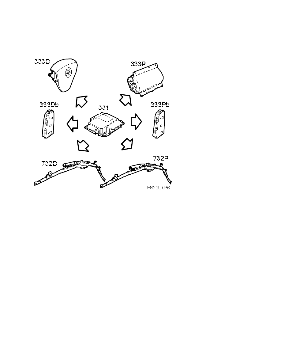
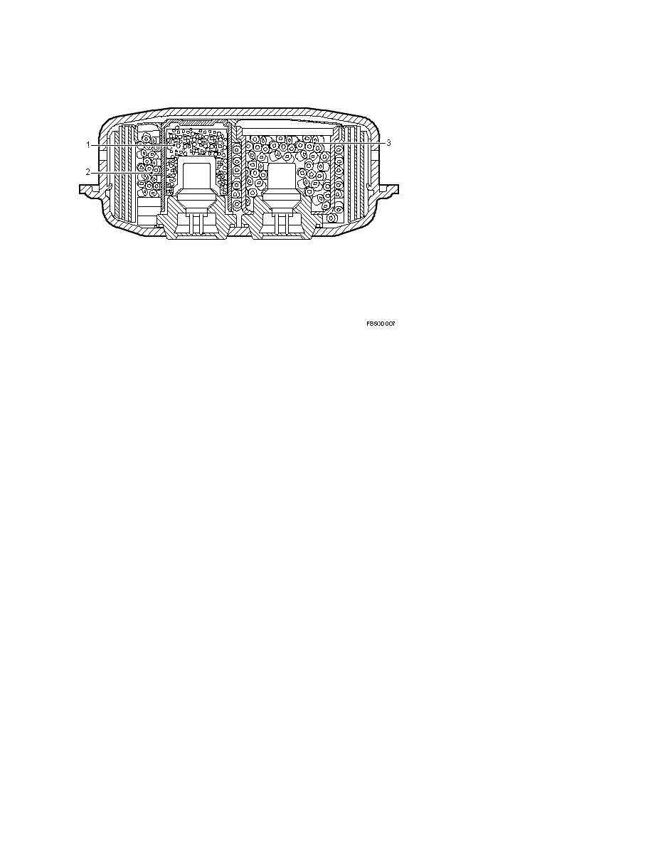
ACM (Airbag Control Module)
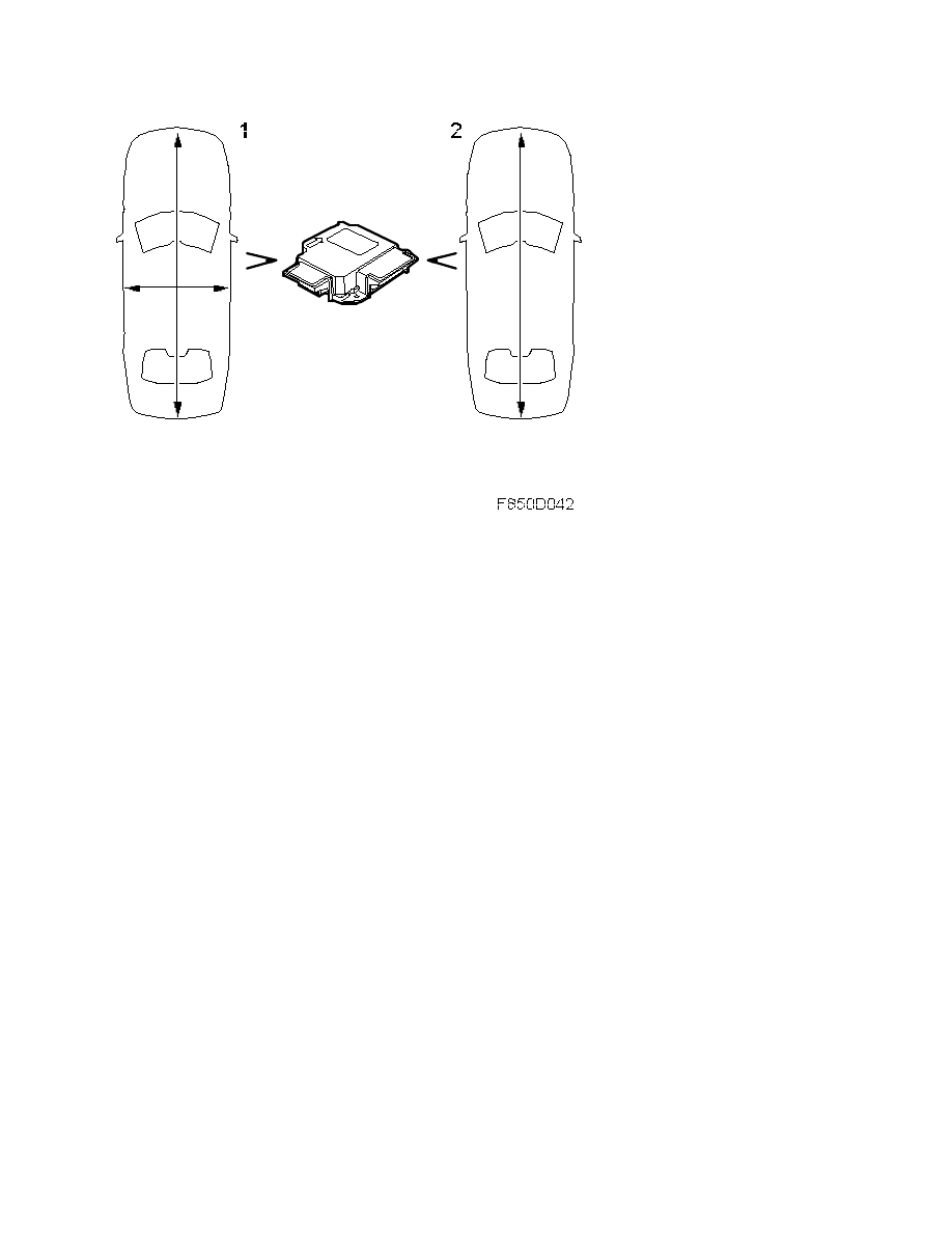
The control module has the capacity to activate 16 detonation circuits and contains two
integrated accelerometers. The primary (1) accelerometer measures acceleration and
deceleration forces longitudinally and laterally. The secondary (2) accelerometer measures
longitudinal acceleration forces only.
8. Body\Airbag system
Technical description - Detailed ...
9-3 (9440) 7 2007
2
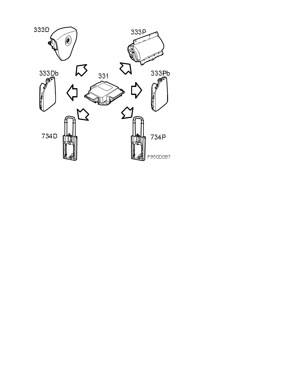
CV: The control module has a roll-over function which means it can measure angle changes.
Angle changes are registered through an extra sensor in the control module.
Four side impact sensors send information to the control module regarding side impact
intensity and diagnostics. The side impact sensors deploy a side airbag and an inflatable
curtain on the side registering an impact.
Conditions
The system can be activated at several levels based on the impact force, seat position and use
of belts. It is activated individually for the driver and passengers, which means that different
decisions can be made for action depending on the seat position and whether or not the belt is
in use.
The front airbags are activated in step 1 or step 2 under different impact forces.
Step 1 means a low force impact and step 2 a high force impact. The front airbag is activated
earlier if the seatbelt is not fastened.
CV: The roll-over function measures the angular velocity with a gyro and is dependent on the
vehicle speed.
Front collision:
At low force impact, the belt tensioners are used. One condition for activation of the driver
and front-seat passenger belt tensioners is that the belt is in use.
If the impact force is greater, the front airbags are also activated in step 1 or step 2.
Step 1:
8. Body\Airbag system
Technical description - Detailed ...
9-3 (9440) 7 2007
3

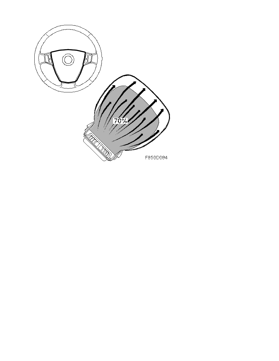
At this level, the battery disconnect switch and the first of the two stages of the front airbags
are also activated, which means that around 70% of the maximum pressure is attained.
Step 2:
4D, 5D: At high impact force, the inflatable curtains and the second stage of the front airbag
are activated. CV: At high impact force, the roll bars and the second stage of the front airbag
are activated
Stage two is activated after a 5 to 20 ms delay after stage one in order to maximise
protection. Activation of stage two presumes that stage one (70% of max. pressure) and the
charge for stage two (during which the remaining 30% of the max. pressure is used) have
been triggered. Stage two is only triggered if the seat is more than 30% from its frontmost
position. This applies driver's seats in all markets as well as passenger seats in some markets.
In situations where the front airbags are only activated in stage 1, there will be a safety
activation of stage 2 after 100 ms for the passenger and 50 ms for the driver irrespective of
seat position. This is done to disarm the airbag and ensure there is no charge left after the
crash.
Side impact
4D, 5D: In the event of a side impact, only the side airbag and inflatable curtain on the side
of the impact will inflate but all belt pretensioners are activated. A precondition for the driver
and passenger belt pretensioner being activated is that the belt is being used.
CV: In the event of a side collision the appropriate side airbag is activated and both roll bars
are raised. The side air bag protects both the head and the torso. All the belt pretensioners
are activated. A precondition for the driver and passenger belt pretensioner to be activated is
that the belt is buckled up.
Backup power
The control module is equipped with a built-in backup power source which provides voltage for
150 ms after the normal power supply has been disconnected. The function has three
capacitors which maintain system current and allow for front airbag deployment during the
150 ms interval. The side impact sensors are disabled in order to save energy. During the
time interval, bus communication occurs continuously.
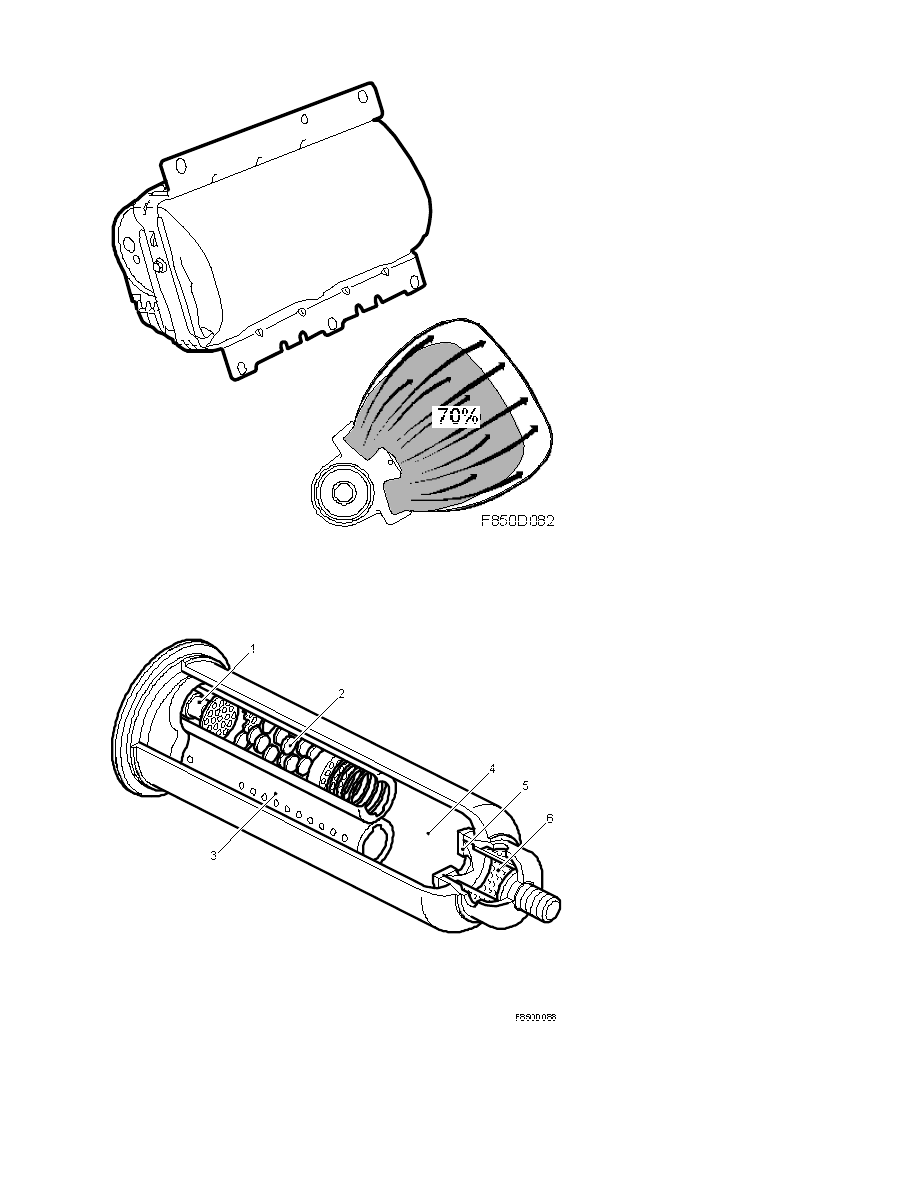
Driver airbag
There is a gas generator and a nylon fabric bag on the driver side. The gas generator is bolted
in a thermosetting plastic housing. The airbag is protected by a plastic casing with notches
that is fitted to the plastic housing. The airbag has a volume of about 60 litres.
8. Body\Airbag system
Technical description - Detailed ...
9-3 (9440) 7 2007
4
The airbag is of a two stage type. This means that it can be activated in two stages with
different pressures depending on the force of impact and the position of the seat. The airbag
consists of a thermosetting plastic housing, two electric detonators with different codings and
two pyrotechnical charges with different amounts of powder for stages 1 and 2 as well as a
filter.
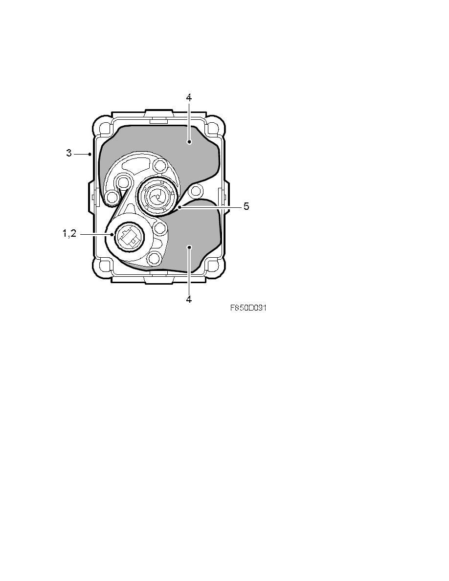
Driver airbag gas generator
8. Body\Airbag system
Technical description - Detailed ...
9-3 (9440) 7 2007
5
1. Initiator
2. Gas generator, 70%
3. Gas generator, 30%
The gas generator is split into two stages. These stages are divided into a primary stage of
70% and a secondary stage of 30%. Depending on the information the control module
receives from the different sensors, the two stages are activated after different time delays.
See control module information.
The gas generator consists of an alloy housing, an initiator (1), two electric detonators, two
explosive charges and a filter.
The primary stage (2) contains a 24 g charge and the secondary stage (3) contains a 6.7 g
charge. When an activation command is received, the control module sends a current pulse to
the detonators, which ignites the charges and produces a gas. The filter cools and purifies the
gas before it is released into the bag.
Passenger airbag
A passenger airbag is standard equipment for all models. It is mounted in the dashboard and
steering wheel member above the glove box on the passenger side and is connected to the
control module. See control module information for conditions.
8. Body\Airbag system
Technical description - Detailed ...
9-3 (9440) 7 2007
6
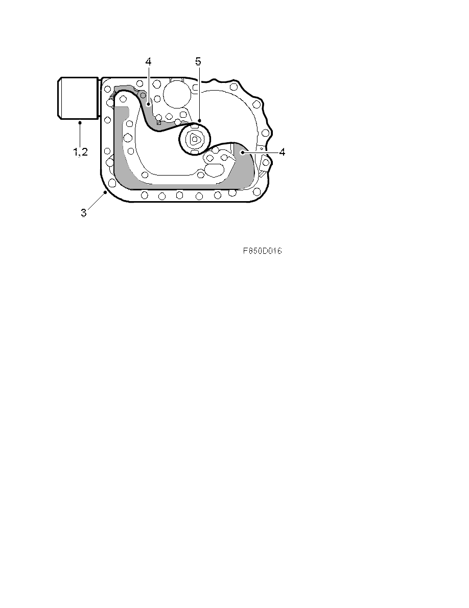
Passenger airbag gas generator
8. Body\Airbag system
Technical description - Detailed ...
9-3 (9440) 7 2007
7

1. Detonator
2. Driver charge, gas generator 70%
3. Driver charge, gas generator 30%
4. Gas cartridge
5. Diaphragm
6. Gas distribution unit, filter
The passenger airbag contains a gas generator and airbag with a volume of approx. 101 litres.
The gas generator is screwed to the airbag housing, which in turn is screwed to the
dashboard. A scored sheet of foil holds the airbag in place. The dashboard contains
corresponding scores.
The gas generator consists of a steel housing with two electric detonators, two explosive
charges with different amounts of propellant for stages one and two, pressurised gas and a
gas distribution unit.
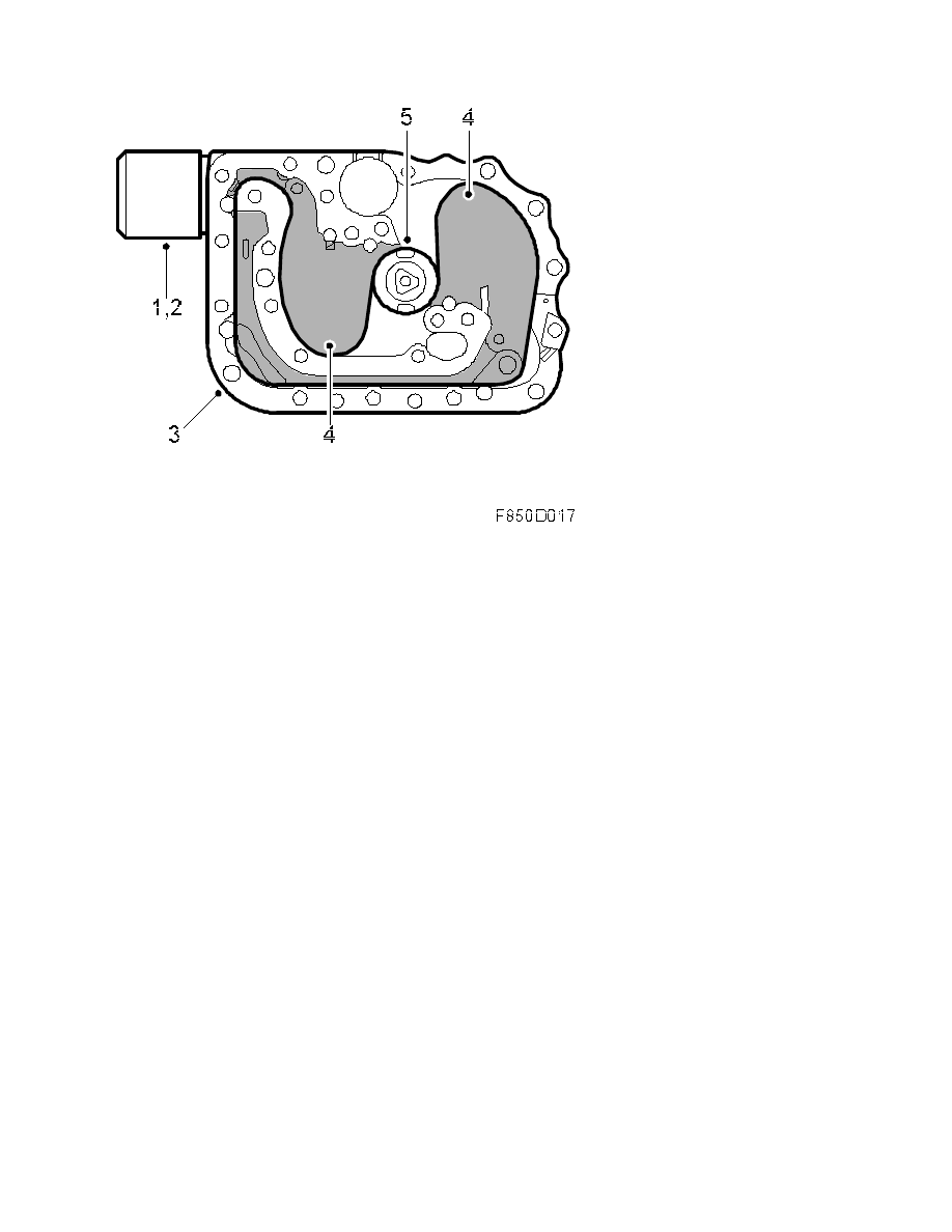
The dual-stage gas generator includes a primary stage of 70% of the pressure and a
secondary stage of 30%. Depending on the information received by the control module from
the various sensors, the two stages are ignited after different intervals. See control module
information for conditions.
After a command for activation, the control module energises the detonators (1), which ignite
the charges (2 and 3). A charge of 28.4 g (2) is ignited in stage 1 and a further charge of 4.3
g (3) in stage 2. The compressed gas expands due to the heat that is generated and passes a
gas distribution unit (6) before it continues to the bag.
The gas mixture consists of
•
98% Argon
•
2% Helium
The front impact sensors detect possible impact intensity at an early stage and send
information to the control module. The front impact sensors send digital information
containing the status message for diagnosis and the acceleration value in 120 levels to the
control module via the lead. The control module performs a calculation and decides whether to
activate the detonators. If the front impact sensors are not functioning, the airbags are still
activated but with a slightly later detonation. See control module information. The front
impact sensors are black.
8. Body\Airbag system
Technical description - Detailed ...
9-3 (9440) 7 2007
8
The front impact sensors communicate by modulating the continuous voltage feed from the
airbag control module which means that the sensors use more or less current. Changes are
registered by a microprocessor in the control module.
1. Identification message - during start-up
2. Status message for diagnostics every 220 ms (as an information packet).
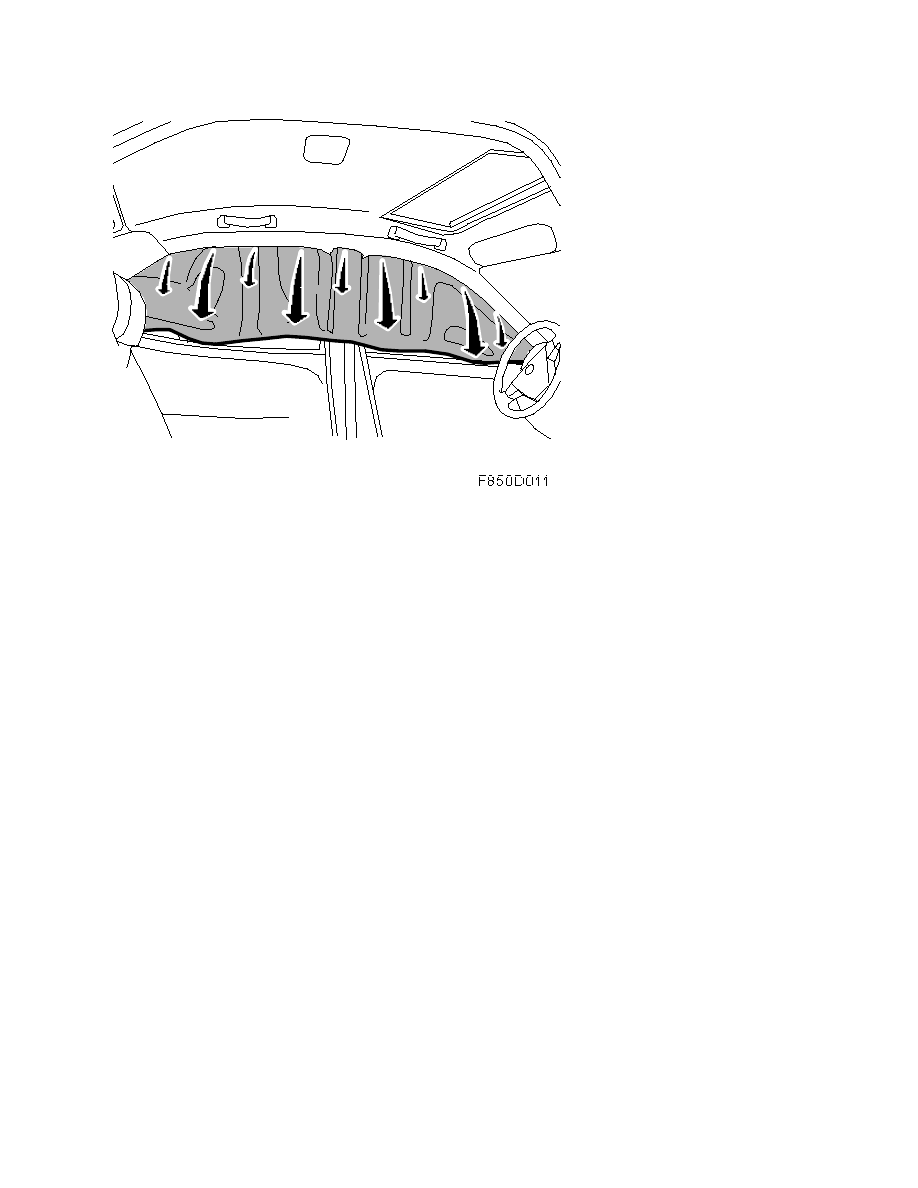
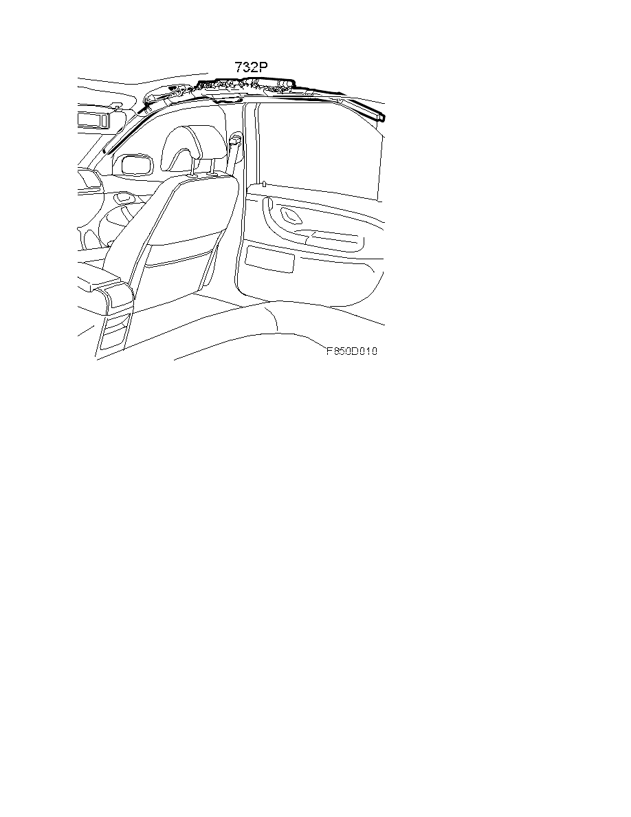
The inflatable curtain consists of a nylon bag with an approximate volume of 17 litres and a
gas generator. During a side impact, the gas generator fills the curtain with gas. By forcing
away the headlining, the curtain is positioned within approximately 20 milliseconds and
provides passengers in the front and rear seats with effective safeguard against head injury
and glass fragments.
8. Body\Airbag system
Technical description - Detailed ...
9-3 (9440) 7 2007
9

The inflatable curtain is a part of the entire protection system available in the event of a side
collision. The protection is supplemented by a side airbag for the driver and front seat
passenger. During a side impact, the inflatable curtain is activated to provide head protection
for front and rear seat passengers and a side airbag is activated for the driver and front seat
passenger on the side of the impact.
The inflatable curtain is also activated in the event of a head-on collision when stage 2 is
activated.
8. Body\Airbag system
Technical description - Detailed ...
9-3 (9440) 7 2007
10
The inflatable curtain is located under the headlining along the roof member from the A-pillar
to the C-pillar and is mounted in the body with four screws and three clips. Fixation clips A
and B as well as the third clip are removable and should be replaced if damaged.
Inflatable curtain, 5D
The inflatable curtain consists of a nylon bag with an approximate volume of 30 litres and a
gas generator. During a side impact, the gas generator fills the curtain with gas. By forcing
away the headlining, the curtain is positioned within approximately 20 milliseconds and
provides passengers in the front and rear seats with effective safeguard against head injury
and glass fragments.
8. Body\Airbag system
Technical description - Detailed ...
9-3 (9440) 7 2007
11
The inflatable curtain is a part of the entire protection system available in the event of a side
collision. The protection is supplemented by a side airbag for the driver and front seat
passenger. During a side impact, the inflatable curtain is activated to provide head protection
for front and rear seat passengers and a side airbag is activated for the driver and front seat
passenger on the side of the impact.
The inflatable curtain is also activated in the event of a head-on collision when stage 2 is
activated.
8. Body\Airbag system
Technical description - Detailed ...
9-3 (9440) 7 2007
12

The inflatable curtain is located under the headlining along the roof member from the A-pillar
to the C-pillar and is mounted in the body with two screws, three nuts and three clips. The
clips are exchangeable and should be replaced if damaged.
Inflatable curtain gas generator, 4D
The gas generator is mounted on a metal bracket which rests on the rear courtesy handle
bracket. Gas is forced into the inflatable curtain through a steel pipe during deployment.
The gas mixture in the gas generator consists of 70% argon, 20% nitrogen oxide and 10%
helium. The charge contains 0.5 grams of propellant.
When the gas generator is activated, the initiator (1) receives voltage and ignites the charge.
The charge causes the inner diaphragm (3) to burst and the energy starts a chemical reaction
inside the chamber (2).
8. Body\Airbag system
Technical description - Detailed ...
9-3 (9440) 7 2007
13
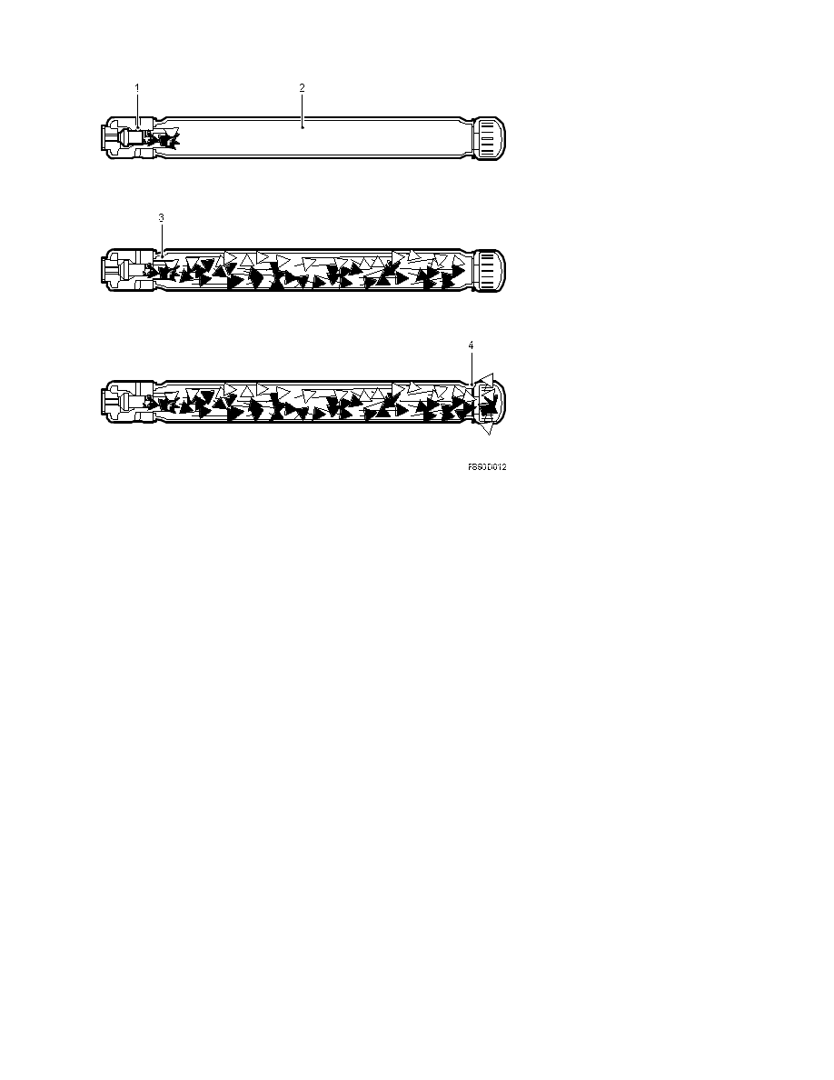
When the gas begins to react, the pressure inside the chamber increases, causing the outer
diaphragm (4) to burst so that the gas can flow out via a gas distributor and fill the inflatable
curtain.
Inflatable curtain gas generator, 5D
The gas generator is mounted on a plastic housing that is fastened to the B-pillar. When
activated, the gas passes into the inflatable curtain through a plastic tube.
The gas mixture in the gas generator consists of 97% argon, 3% helium. The charge contains
0.5 grams of propellant.
8. Body\Airbag system
Technical description - Detailed ...
9-3 (9440) 7 2007
14
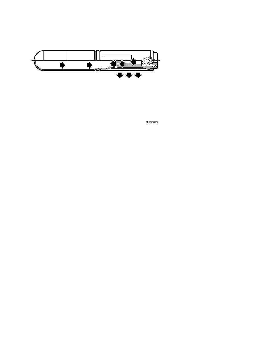
The following happens when the gas generator is activated:
•
An electric pulse melts an electric jumper, which initiates the detonation of the
pyrotechnical charge in the chamber.
•
The temperature rises during the detonation
•
Pellets generate a gas that flows out of the combustion chamber jets in a heated
state.
•
A metal disc ruptures on the other side of the combustion chamber and the stored
cold gas (97% argon and 3% helium) flows out.
•
Cold and hot gas is mixed in the filter chamber and the mixed gas is filtered and
flows out to fill the inflatable curtain
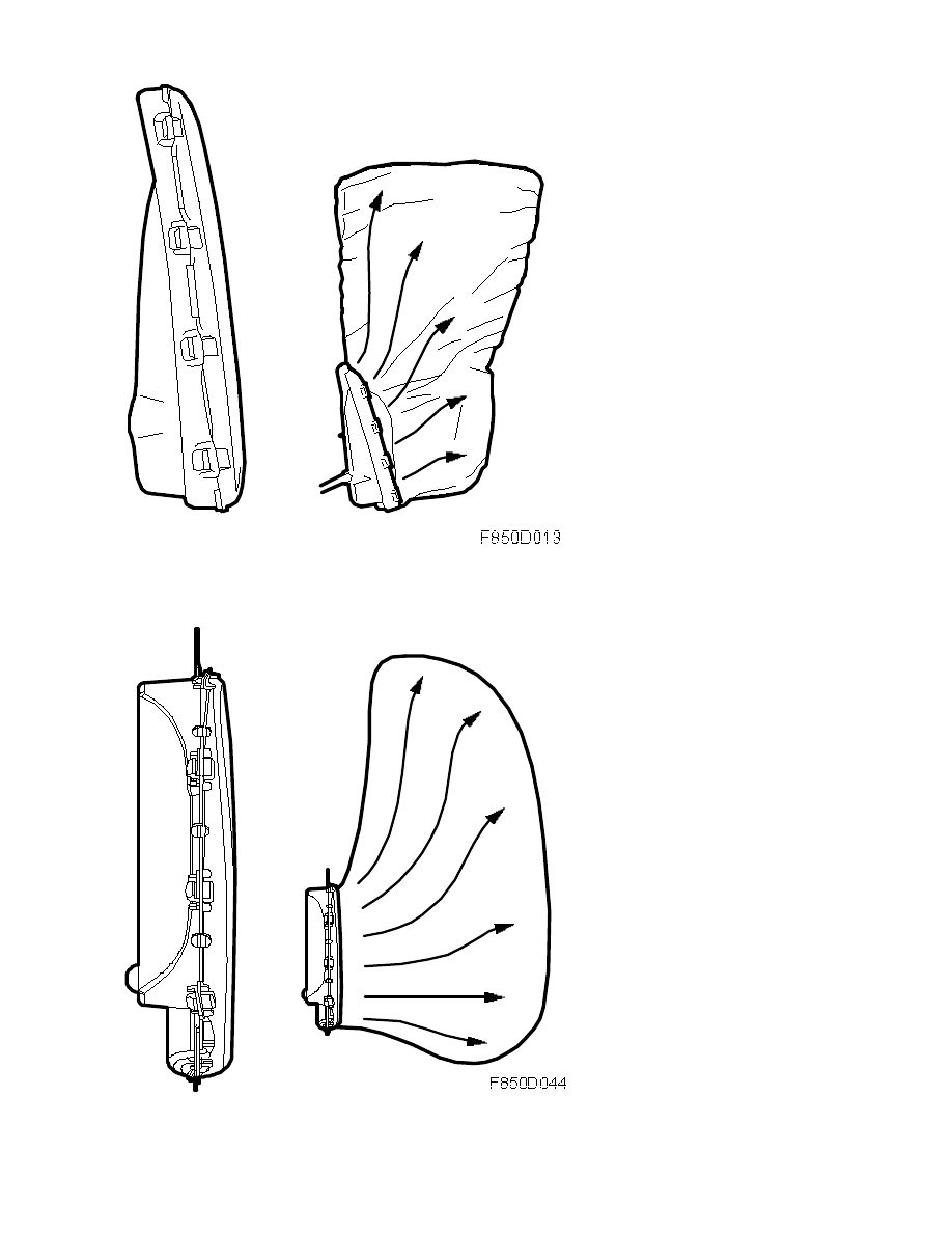
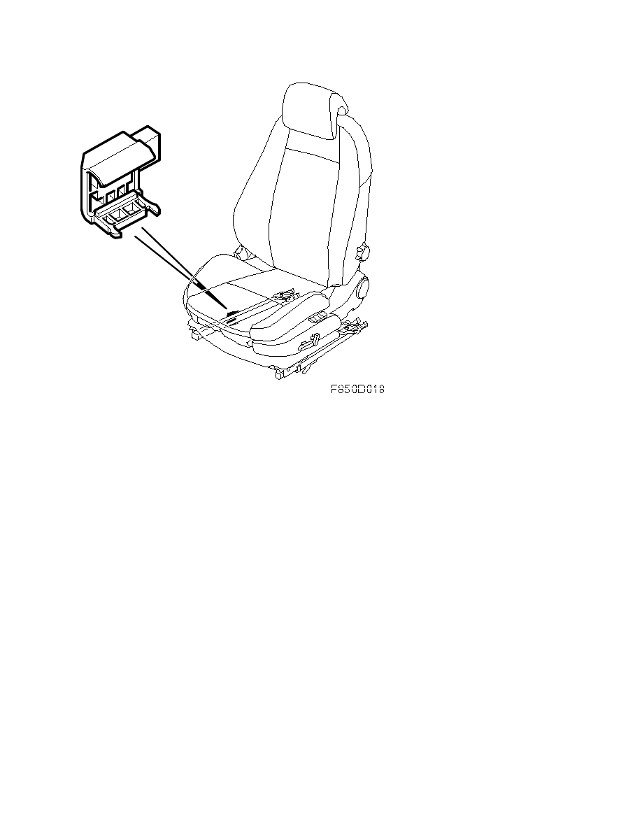
The purpose of the side airbag is to reduce the effects of a side impact on the person sitting
on the side involved in the collusion. This is achieved by an airbag which inflates between the
passenger's upper body and the door. CV: The side airbag protects both the head and the
upper body.
4D, 5D
8. Body\Airbag system
Technical description - Detailed ...
9-3 (9440) 7 2007
15
CV
8. Body\Airbag system
Technical description - Detailed ...
9-3 (9440) 7 2007
16
4D, 5D: This protection is supplemented with an inflatable curtain, which provides head
protection for the driver and front and rear seat passengers. In the event of side impact an
inflatable curtain is activated to protect the heads of the driver and front and rear seat
passengers.
The side airbag is activated for the driver or front seat passenger on the side where the crash
has occurred. In the side airbag there is a gas generator and a bag. The bag has a volume of
approx. 9 litres (approx. 20 litres for CV). The bag and gas generator are protected by a
plastic case with clips, which opens on activation.
The side airbag is available in different variants depending on the market and the location of
the steering wheel in the vehicle.
Side airbag gas generator
The gas generator consists of a steel housing, electric detonator, explosive charges with
different amounts of propellant for stages one and two, pressurised gas and a gas distribution
unit for gas cooling and pressure distribution.
When a deployment command is received, the control module sends a current pulse to the
electric detonator which starts fuel combustion. When the electric detonator (1) is activated,
the explosive charge is ignited (2). The charge expands and forces a projectile (3) through the
diaphragm (4) to the pressure vessel (5) due to the pressure and heat build-up. The gas is
mixed with the charge, which expands due to the increase in heat. The pressure forces a
diaphragm (6) to burst in another part of the gas generator and the gas flows into the bag via
a gas distributor.
8. Body\Airbag system
Technical description - Detailed ...
9-3 (9440) 7 2007
17
Side impact sensor
The gas mixture is 95% argon and 5% helium.
Gas pressure: approximately 350 bar.
1. Detonator
2. Charge
3. Projectile
4. Diaphragm, inner
5. Pressure chamber
6. Outer diaphragm and gas distributor
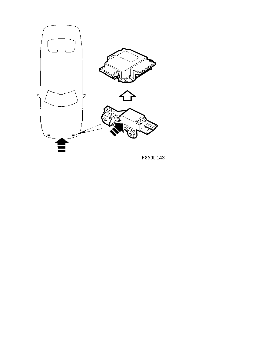
The purpose of the side impact sensor includes early impact detection and providing
information to the control module. The sensor contains an acceleration sensor and a
communication circuit. This sends digital information containing status messages for
diagnostics and acceleration values in 120 levels to the control module via wiring. Calculations
and decisions regarding detonation occur in the control module. The control module increases
the level of sensitivity and measures more precisely.
4D, 5D
8. Body\Airbag system
Technical description - Detailed ...
9-3 (9440) 7 2007
18
CV
8. Body\Airbag system
Technical description - Detailed ...
9-3 (9440) 7 2007
19
All side impact sensors are identical and yellow in colour.
4D: The car is fitted with four side impact sensors.
CV: The car is fitted with two side impact sensors.
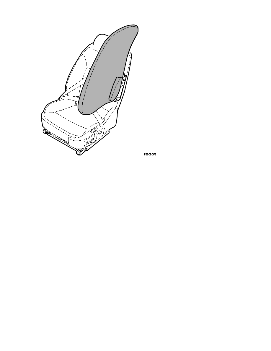
Belt tensioners
4D, 5D
The car is equipped with belt tensioners on the driver and front passenger seats. The seat belt
tensioner pyrotechnic charges are built into the belt tensioner housing. Silicone is used as a
sealant in order to reduce gas emissions arising from the activation of the pyrotechnical
charges. The belt tensioners are mounted in the lower part of the B-pillars and the sills.
Function
The belt tensioner pulls the belt taut during the event of a collision, reducing forward
movement of the driver or passenger. Additionally, force limiters release the belt according to
a controlled sequence.
The seat belt tensioner consists of a pyrotechnic charge that is activated by the airbag control
module together with the airbags. The seat belt tensioners can also be activated separately
with a minor head-on collision.
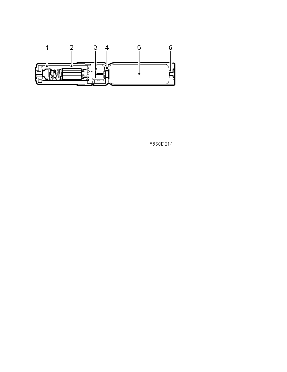
The belt tensioners are compact type. When the belt tensioners are activated, the airbag
control module sends a B+ voltage. An electric detonator (1) ignites a pyrotechnical charge
(2), which generates a gas pressure that expands in the belt tensioner housing (3).
8. Body\Airbag system
Technical description - Detailed ...
9-3 (9440) 7 2007
20
The gas passes into a chamber (4) that moves a steel band (5), which takes with it the belt
strap. The belt is pulled taut, pulling back the passenger. The belt is contained using a power
limiting torsion part of the inertia reel and the body is held in check as gently as possible.
CV
The car is equipped with belt tensioners for the driver and front seat passenger as well as
outer rear seats. The front belt tensioners are integrated in the seat and mounted in the lower
section of the seat for the driver and passenger. The rear belt tensioners are mounted behind
the backrest on the rear seats.
Function
The belt tensioner pulls the belt taut during the event of a collision, reducing forward
movement of the driver or passenger. Additionally, force limiters release the belt according to
a controlled sequence.
The seat belt tensioner consists of a pyrotechnic charge that is activated by the airbag control
module together with the airbags. The seat belt tensioners can also be activated separately in
a minor head-on collision. The belt tensioners are compact type. When the belt tensioners are
activated, the airbag control module sends a B+ voltage. An electric detonator (1) ignites a
pyrotechnical charge (2), which generates a gas pressure that expands in the belt tensioner
housing (3).
8. Body\Airbag system
Technical description - Detailed ...
9-3 (9440) 7 2007
21
The gas flow is distributed into two chambers (4) which move a steel band (5) which tightens
the seat-belt. The belt is pulled taut and takes up the slack in the belt while restraining the
passenger. The belt is taken up aided by a force-limiting torsion unit in the belt roller which
restrains bodily movement as gently as possible.
8. Body\Airbag system
Technical description - Detailed ...
9-3 (9440) 7 2007
22
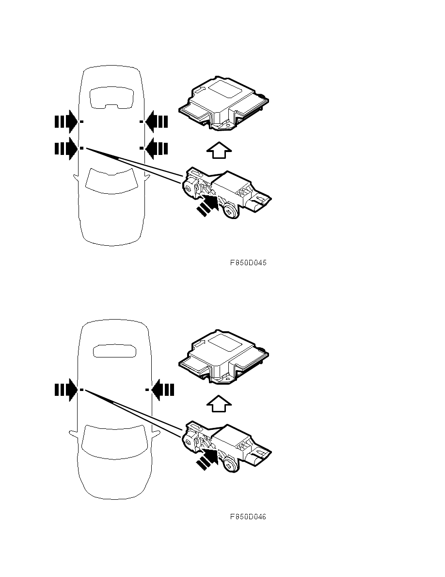
Seat position sensor
The car is equipped with a seat position sensor on the driver's side. In some markets, the
sensor is also found on the passenger side. The seat position sensor is used to detect whether
the seat is in a forward position, i.e. less than 30% from the frontmost position of the seat. It
is also used to detect whether the seat is in a rear position, i.e. more than 30% from the
frontmost position of the seat.
When the control module receives information from the seat position sensor, the control
module determines how the detonation circuits should be activated. See control module
information. Seat position sensors are mounted on both manual and electric seats.
Cables are used for power supply and communication between the seat position sensor and
the control module. The sensor provides the control module with a constant current. The level
of amperage is dependent on whether or not the sensor is affected.
•
Forward position, < 30% 2-7 mA
•
Rear position, > 30% 12-18 mA
The seat position sensor consists of a magnetic strip (2) which is mounted on the section of
the seat rail fixed to the floor. A Hall sensor (1) is mounted on the moveable upper seat rail.
When the seat is between the forward position and 30% towards the rear, the Hall sensor is
not affected by the magnetic strip. The control module provides the Hall sensor with constant
voltage and measures once every 100 ms while simultaneously measuring which current is
passing through the sensor. The current through the Hall sensor is dependent on the magnetic
field which affects the sensor.
8. Body\Airbag system
Technical description - Detailed ...
9-3 (9440) 7 2007
23
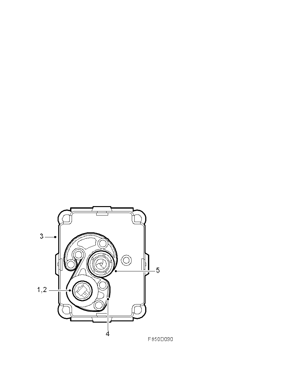
Seat-belt buckle
The sensor detects if the seat-belt buckle is fastened or unfastened. Using information from
the seat-belt buckle sensors and seat position sensors, the airbag control module determines
if the belt tensioner detonation circuits should be activated. The front belt tensioners can be
activated individually while the tensioners for the outer rear seat passengers are always
activated simultaneously with at least one of the front belt tensioners.
The seat-belt buckle sensors consist of a Hall sensor (1) containing a circuit board and a
magnet (2) which is mounted in front of the Hall sensor on the belt mechanism. The sensor
detects the magnetic field generated by the fixed magnet.
8. Body\Airbag system
Technical description - Detailed ...
9-3 (9440) 7 2007
24
When the belt tongue (3) is not inside the buckle, the magnet (2) lies near the sensor. When
the tongue is fastened, the magnet (2) is moved from the Hall sensor and the magnetic field
is altered.
8. Body\Airbag system
Technical description - Detailed ...
9-3 (9440) 7 2007
25
•
Unfastened: 2.0-7.0 mA
•
Fastened: 12.0-18.0 mA
The airbag control module provides voltage to the Hall sensor every 100 ms while
simultaneously measuring the amount of current passing through the sensor. The current
passing through the Hall sensor is dependent on the magnetic field that affects the sensor.
The airbag control module sends out a bus message and the BCM uses this information in
order to switch on the seat-belt warning.
Roll bar unit
Overview
8. Body\Airbag system
Technical description - Detailed ...
9-3 (9440) 7 2007
26
General
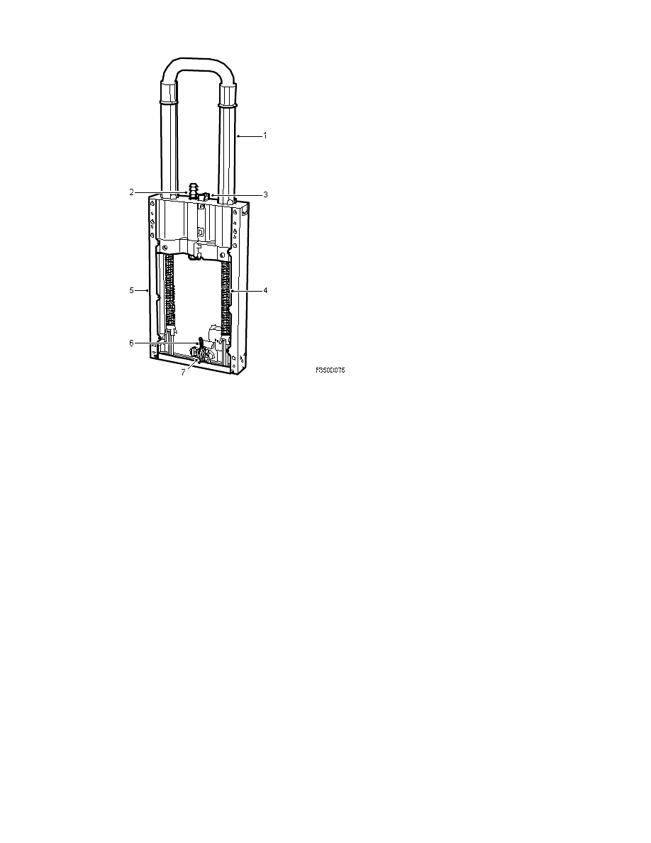
1. Roll bar unit
2. Lock bolt
3. Upper lock hook
4. Spring
5. Cassette
6. Lower lock hook
7. Activation unit, roll bar (734D/P)
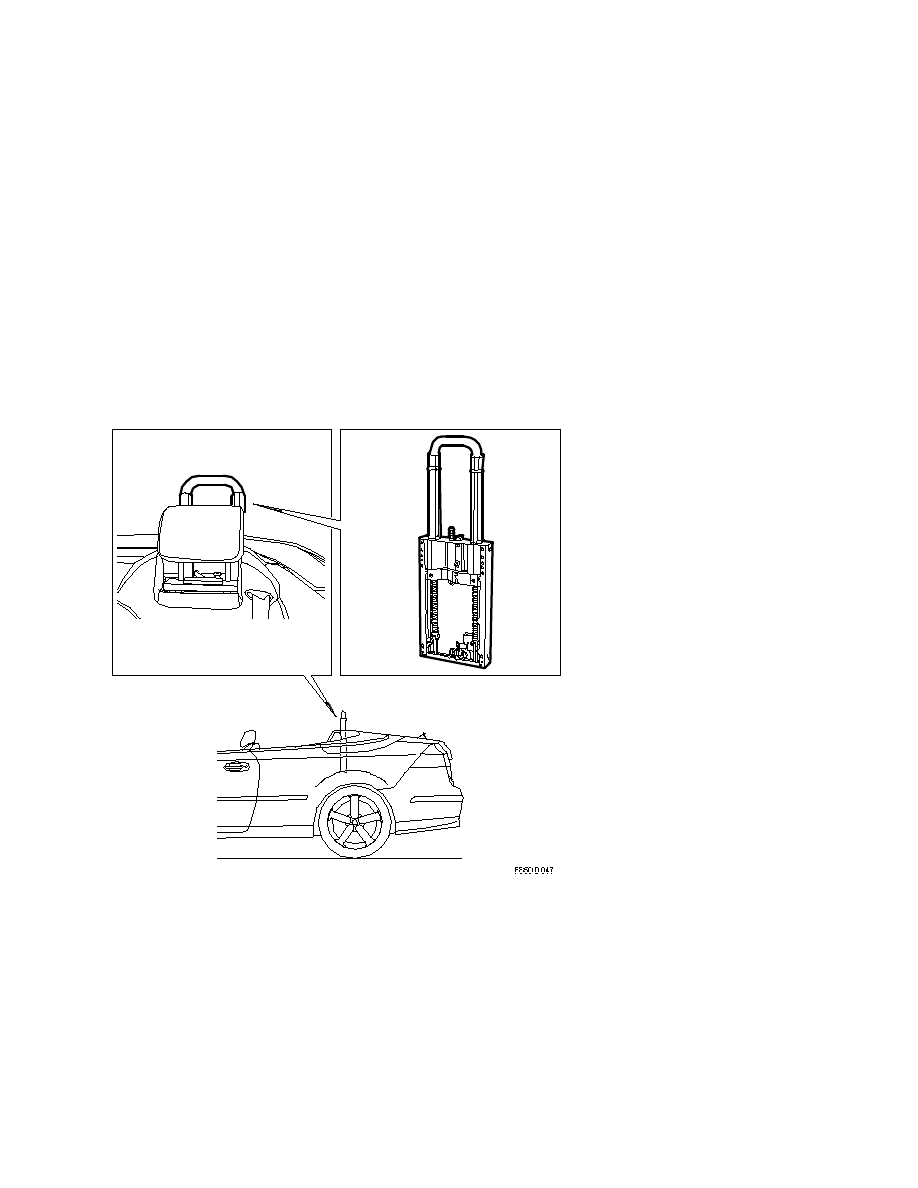
To improve safety in the event of a rollover accident, the car is fitted with roll bars which are
activated by the car airbag control module (ACM). In a rollover accident, two roll bars are
extended from behind the rear seat backrest to protect the passengers. The roll bars are part
of the vehicle's passive safety equipment. The protection system with bows consists of two
cassettes mounted behind the rear seat.
Equipment
The roll bar unit cassette (5) is bolted to the body. The lower catch (6) locks the roll bar in its
8. Body\Airbag system
Technical description - Detailed ...
9-3 (9440) 7 2007
27
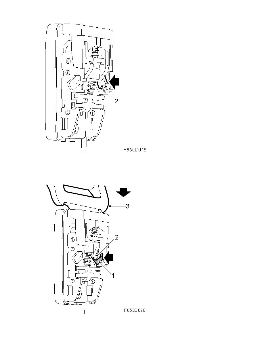
lowered position. The upper catch with release mechanism (3) locks the roll bar lock bolt (2)
in raised position at the same time as releasing the return of the roll bar. In lowered position,
the system is held against two pretensioned springs (4) and held with a lock integrated in the
pyrotechnical activation unit (7).
Checking and activation
The system is activated by the airbag control module ACM which contains an angle sensor to
measure whether the car is rolling. The roll bars are activated by the ACM and extended
immediately. The customer cannot activate the bow himself. On automatic trigger controlled
by the angle sensor in the airbag control module (ACM), the pyrotechnic activation unit (7) is
detonated and releases the lower lock hook (6) which holds the bow down in a pretensioned
position, and the lock is opened. Under spring force the roll bar is extended within 225 ms and
locked in the upper position by means of the upper lock hook (3) and locking bolt (2).
The roll bar (1) can also be triggered manually by turning the axle of the lower lock hook (6).
To be able to do this, the front luggage compartment trim and both roll bar covers must be
removed.
Warning
Make sure there are no objects or persons obstructing
the motion of the roll-over bars when they are
activated. Uncontrolled projectiles can cause personal
injury.
On manual activation of the roll bar, the upper lock hook (3) must first be pressed down
before the roll bar can be returned to the down position. The lower lock hook (6) locks the
bow in its down position.
Retracted position, the lower lock hook locks the bow.
8. Body\Airbag system
Technical description - Detailed ...
9-3 (9440) 7 2007
28
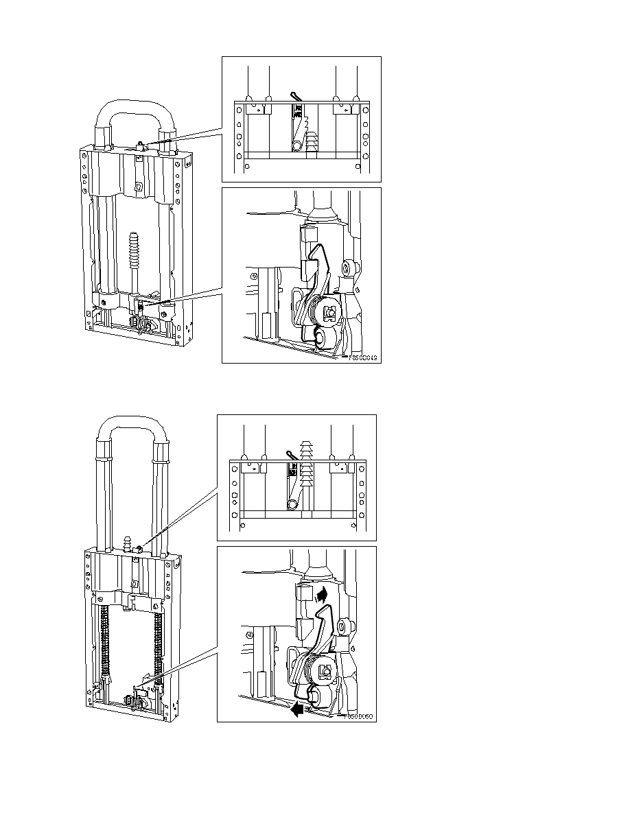
Extended position, the upper lock hook locks the roll bar.
Airbag warning lamp
8. Body\Airbag system
Technical description - Detailed ...
9-3 (9440) 7 2007
29
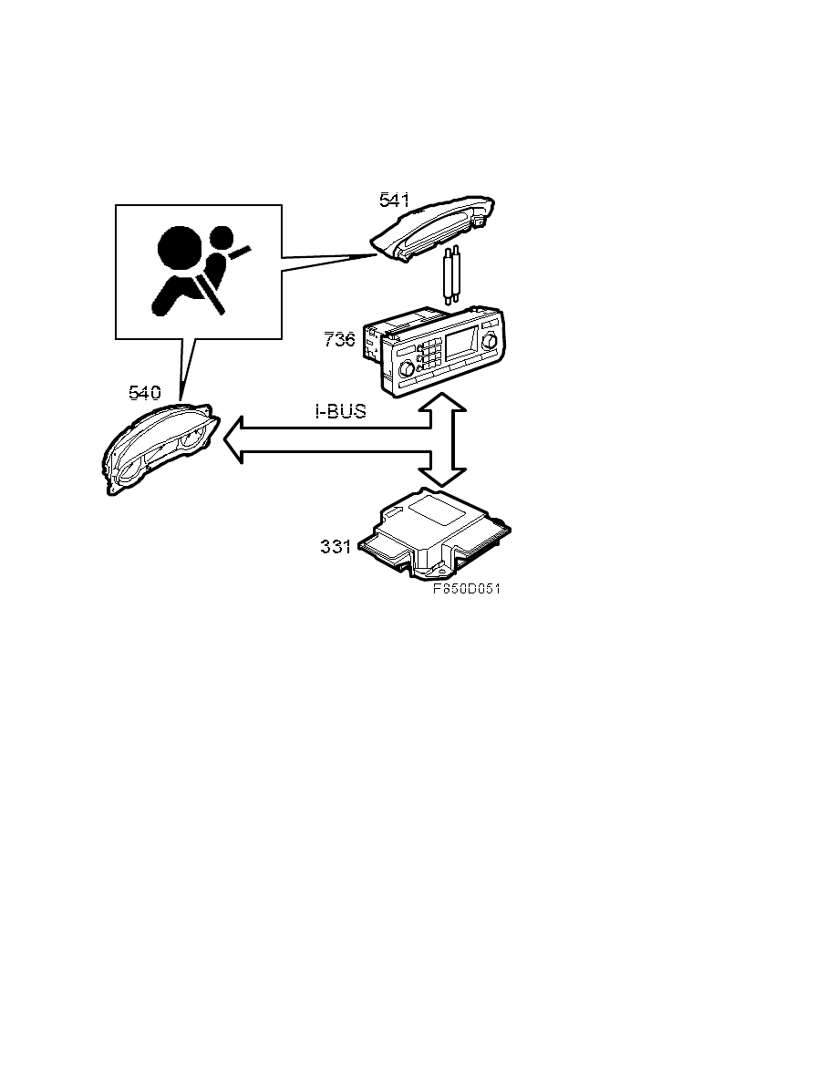
When the ignition key is turned to the start or drive position, the airbag warning lamp on the
main instrument unit MIU lights for 3-4 seconds and then goes out if no active fault codes are
stored. For normal function, the airbag control module sends a bus message "Airbag indication
- Off" on the I-bus.
If any active diagnostic trouble codes are stored, the lamp in the MIU will light for 4 seconds
and extinguish for one and a half seconds; whereupon it will light again and remain lit until
the ignition is switched off or the DTC is erased.
An error in the airbag system is indicated by a continuous glow of the airbag warning lamp in
the main instrument panel (MIU) as well as a check message with symbol which is activated in
SID (Saab Information Display).
On a fault in the airbag system, the airbag control module sends a bus message "Airbag
indication - On" via the I-bus. When this message is sent, the MIU lights the airbag warning
lamp and SID activates a check message.
SID shows the airbag warning text "Airbag malfunction. Contact service." together with a
symbol:
If an airbag or seat-belt tensioner has been triggered, the airbag warning lamp will remain lit
continuously.
Message
An airbag system fault will result in a warning message and symbol displayed in SID.
Contact roller
8. Body\Airbag system
Technical description - Detailed ...
9-3 (9440) 7 2007
30
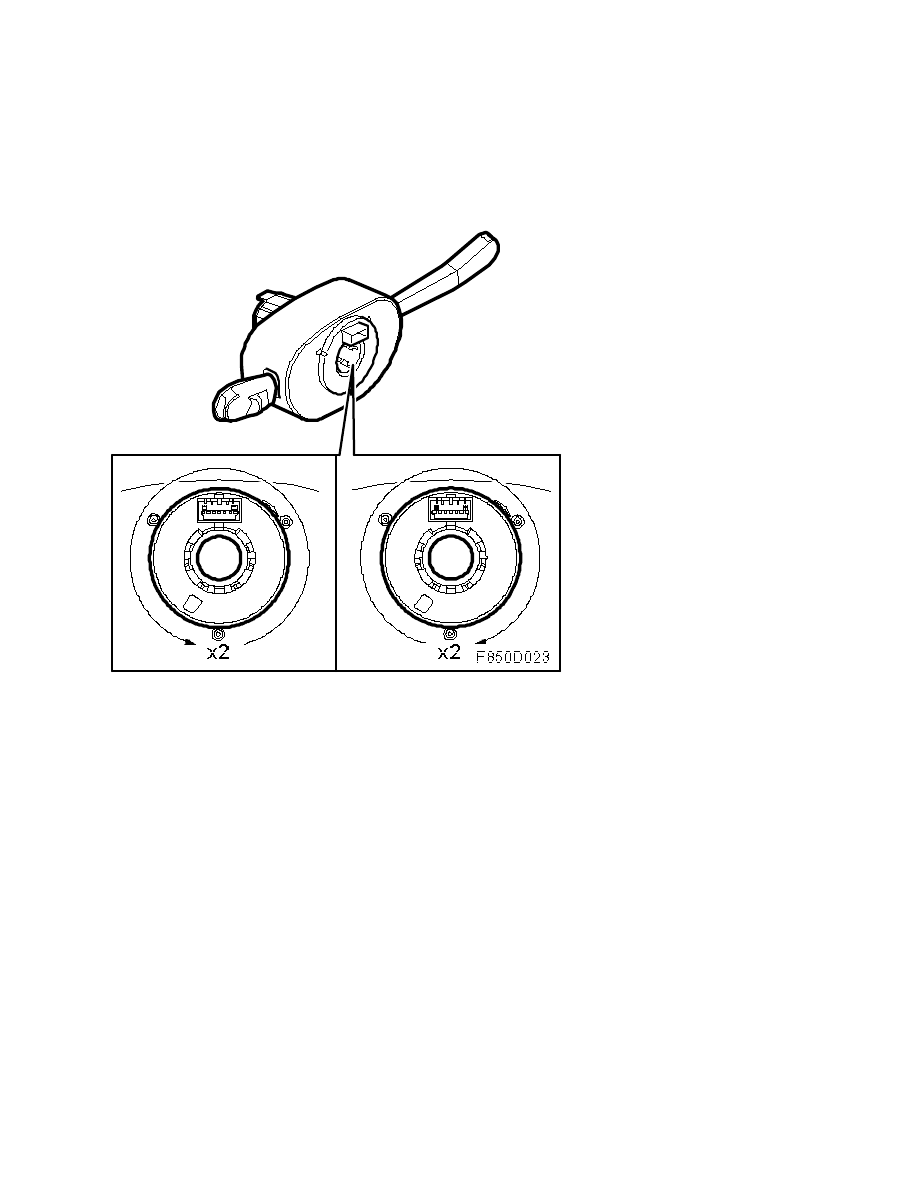
In order to conduct test and detonation current to the driver airbag, a contact roller is located
between the steering wheel and the steering column assembly. The contact roller is mounted
and integrated in the CIM (Column Integrated Module), which means that it is not available as
a separate spare part. The contact roller also conducts current for the horn, audio system,
telephone and speak button.
The contact roller consists of one fixed and one moving part. A spiral plastic tape with eight
embedded leads is fitted between the fixed and moving part. The contact roller forms a
connection between a circuit board in the CIM and the steering wheel. Four of the leads are
connected to the driver airbag.
The moving part of the contact roller can be rotated approximately 4 revolutions, in other
words, approximately 2 turns in either direction from the centre position. If over-rotation
occurs, the spiral tape will break and the SRS system will no longer function. This break is
detected by the control module and the airbag warning lamp will switch on.
8. Body\Airbag system
Technical description - Detailed ...
9-3 (9440) 7 2007
31
Wyszukiwarka
Podobne podstrony:
saab 9 3 awaria systemu kontroli zapiecia pasow
From Plato To Postmodernism Understanding The Essence Of Literature And The Role Of The Author (Deta
IFL90 ch1 System description spec intel
System finansowy w Polsce 2
Systemy operacyjne
Systemy Baz Danych (cz 1 2)
Współczesne systemy polityczne X
System Warset na GPW w Warszawie
003 zmienne systemowe
elektryczna implementacja systemu binarnego
09 Architektura systemow rozproszonychid 8084 ppt
SYSTEMY EMERYTALNE
3 SYSTEMY LOGISTYCZNE
modelowanie systemow
16 Metody fotodetekcji Detektory światła systematyka
ZINTEGROWANY SYSTEM RATOWNICTWA MEDYCZNEGO(1)
więcej podobnych podstron