POWER WINDOWS
CONTENTS
page
page
GENERAL INFORMATION
. . . . . . . . . . . . . . . . . . 1
MOTOR REPLACEMENT
. . . . . . . . . . . . . . . . . . . 2
POWER VENT WINDOWS . . . . . . . . . . . . . . . . . . 3
POWER WINDOW CABLE HOUSING/MOTOR
REPLACEMENT . . . . . . . . . . . . . . . . . . . . . . . . . 2
SWITCH CONTINUITY TEST
. . . . . . . . . . . . . . . . 2
SWITCH VOLTAGE TEST . . . . . . . . . . . . . . . . . . . 1
VENT CABLE AND CRANK MECHANISM
. . . . . . 4
VENT WINDOW MOTOR REPLACEMENT
. . . . . . 5
VENT WINDOW MOTOR TEST
. . . . . . . . . . . . . . 3
VENT WINDOW SWITCH TEST . . . . . . . . . . . . . . 3
WINDOW MOTOR TEST
. . . . . . . . . . . . . . . . . . . 2
GENERAL INFORMATION
Window lift motors are of the permanent magnet
type. A battery positive and negative connection to ei-
ther of the two motor terminals will cause the motor
to rotate in one direction. Reversing current through
these same two connections will cause the motor to
rotate in the opposite direction.
Each individual motor is grounded through the
master switch by a black wire attached to the left
cowl panel.
It is necessary that the window be free to slide up
and down in the glass channels or tubes and tracks.
If the window is not free to move up and down, the
window lift motor will not be able to move the glass.
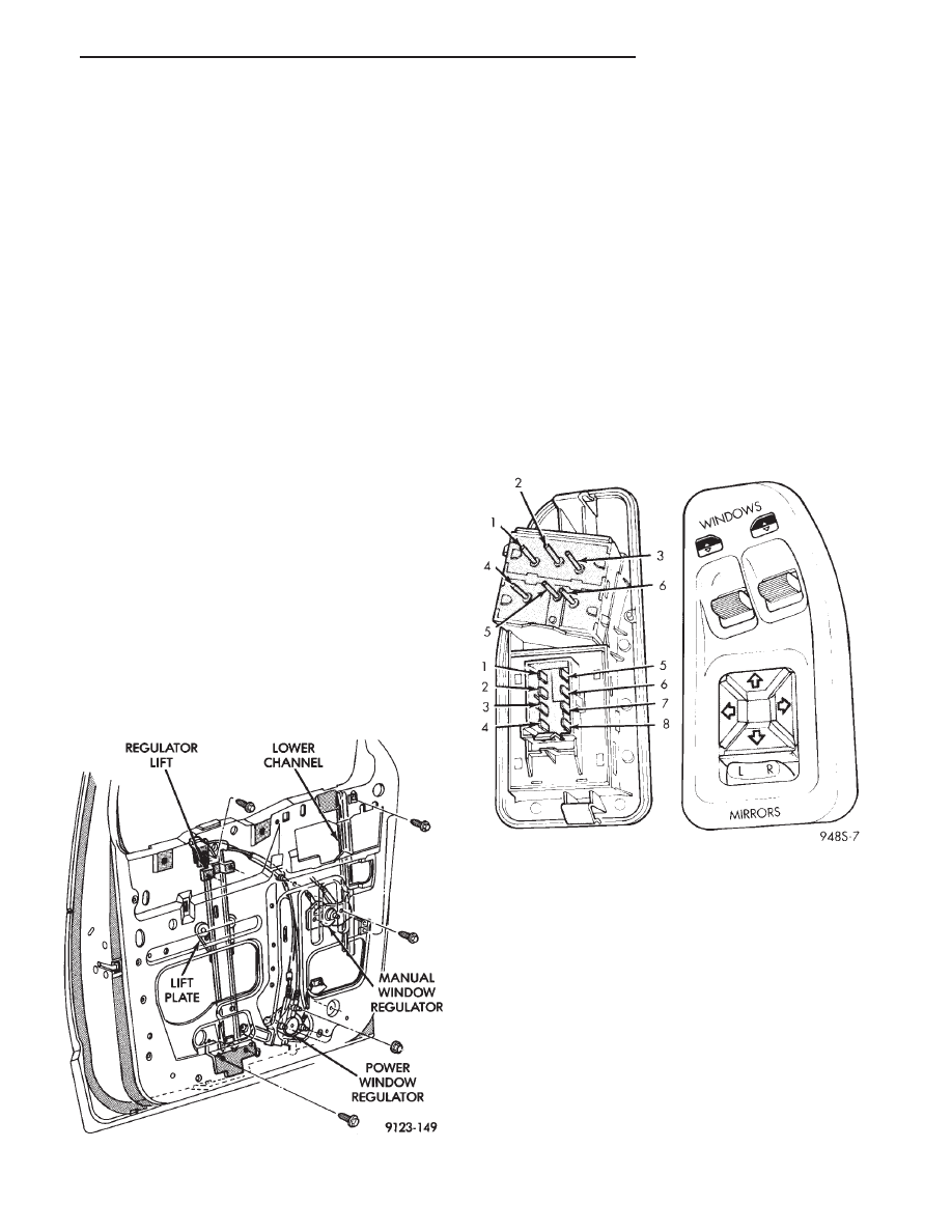
To determine if the glass is free, disconnect the
electric window regulator lift plate from the glass
(Fig. 1). Then slide the window up and down by
hand.
SWITCH VOLTAGE TEST
The following wiring test sequence determines
whether or not voltage is continuous through the
body harness to switch (Fig. 2).
(1) After removing switch from trim panel for test-
ing purposes, carefully separate multiple terminal
block on wiring harness from switch body.
(2) Turn ignition switch to the ON or ACCESSORY
position.
(3) Connect one lead of test light to black wire ter-
minal and touch other test light lead to tan wire ter-
minal.
(4) If the test light comes on, the wiring circuit be-
tween the battery and switch is functional.
(5) If light does not come on:
• Check 20 amp circuit breaker in the micro relay
bank
• A broken feed or ground wire
Fig. 1 Power Window Regulator
Fig. 2 Mirror/Window Switch
.
POWER WINDOWS
8S - 1
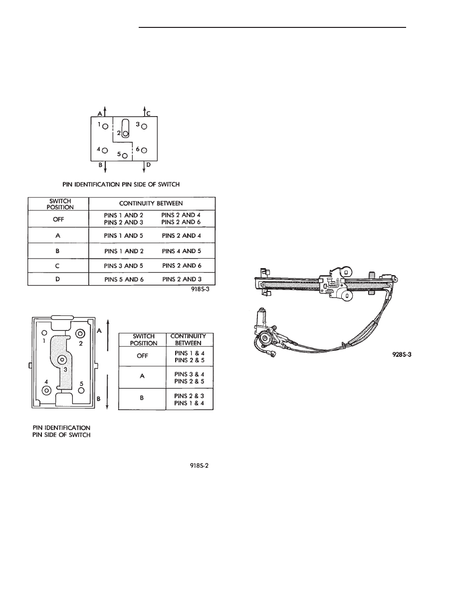
SWITCH CONTINUITY TEST
To check the switch, remove the switch from its
mounting position. Using an ohmmeter, and referring
to the Switch Continuity (Figs. 3 and 4), determine if
continuity is correct. If there is no continuity at any
one of the switch positions, replace the switch.
WINDOW MOTOR TEST
(1) Connect battery positive test lead to either of
the two motor terminals.
(2) Connect battery negative test lead to remaining
motor terminal.
(3) The motor should now rotate in one direction to
either move window up or down.
(a) If window happens to be already in full UP
position and motor is connected so to rotate in UP
direction no movement will be observed.
(b) Also, the motor connected to DOWN direction
rotation, no movement will be observed if window
is already in full down position.
(4) Reverse battery leads (steps 1 and 2) and win-
dow should now move. If window does not move, re-
move motor. See below for motor removal from
vehicle.
(5) If window moved completely up or down, motor
should be reversed one more time (step 4) to com-
plete a full window travel inspection.
(6) If switch voltage, continuity and motor test are
OK, check for open circuit the between motor and
switch.
POWER WINDOW CABLE HOUSING/MOTOR
REPLACEMENT
(1) Remove front door trim panel. Refer to group
23, Body.
(2) Disconnect window lift plate from glass (Fig. 5).
(3) Disconnect window track from door.
(4) Disconnect window lift motor and drive cables.
(5) Disconnect electrical connections.
(6) Carefully remove window track, cables and lift
motor assembly from door.
(7) For installation reverse above procedures.
MOTOR REPLACEMENT
REMOVAL
(1) Refer to Front Door Window Regulator for re-
moval.
(2) The door glass must be in the full up position.
(3) Tape glass to door frame to hold glass in the up
position.
(4) If the window is not in the full up position, re-
move only the motor from the door.
(5) Remove nuts from motor and cable housing
(Fig. 6).
(6) Make sure motor is facing you before separat-
ing motor from housing.
Fig. 3 Master Switch Continuity
Fig. 4 Front Door Window or Rear Vent Window
Switch Continuity
Fig. 5 Cable and Housing/Motor
8S - 2
POWER WINDOWS
.
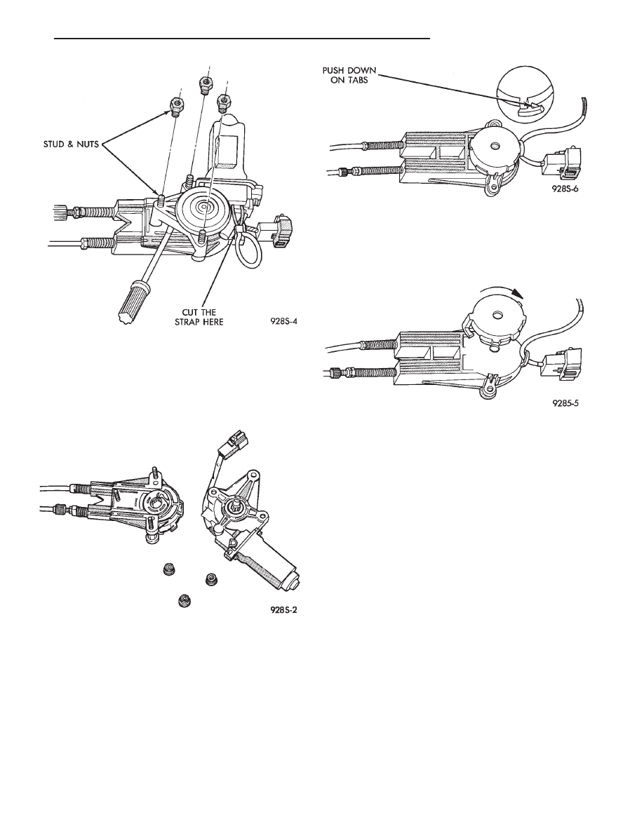
(7) Using a flat tool slowly separate motor from
housing, making sure the cable drum under the mo-
tor stays in cable housing. When motor is fully sepa-
rated the assist spring will be completely unwound
(Fig. 7).
(8) Remove assist spring by releasing the tabs on
the opposite sides of the spring, do not remove spring
from its case (Fig. 8).
INSTALLATION
(1) Install motor into housing with one stud and in
center of housing to secure motor to housing.
(2) Before installing new spring, power the motor
into the full-up position.
(3) Replace assist spring on cable housing. Wind
spring clockwise 3 1/2 turns on the left door. The
right door, wind spring counter clockwise 3 1/2 turns
(Fig. 9).
(4) Install the other two studs and nuts and
tighten to 4 to 5 M
zm (35 to 45 in. lbs.) torque.
(5) Inspect that cables are not twisted prior to in-
stalling motor and housing into door.
POWER VENT WINDOWS
AS-body vehicles have, as an option, power rear
vent windows. The windows are operated by switches
mounted in the overhead console. A separate switch
is used for each window.
The vent window motors are of the permanent
magnet type. A battery positive and negative connec-
tion to either of the two motor terminals will cause
the motor to rotate in one direction. Reversing cur-
rent through these same two connections will cause
the motor to rotate in the opposite direction.
VENT WINDOW SWITCH TEST
For power vent window switch testing, refer to
Group 8C, Overhead Console for Rear Vent Windows
Switch Test.
VENT WINDOW MOTOR TEST
(1) Connect battery positive test lead to either of
the two motor terminals.
(2) Connect battery negative test lead to remaining
motor terminal.
Fig. 6 Separating Motor from Housing
Fig. 7 Cable/Drum and Motor
Fig. 8 Assist Spring Cover
Fig. 9 Wind Assist Spring Cover
.
POWER WINDOWS
8S - 3
(3) The motor should now rotate in one direction to
either move the window OPEN or CLOSED.
(a) If window happens to be already in the full
CLOSED position and motor is connected to rotate
toward the CLOSED position no movement will be
observed.
(b) Also, the motor connected to rotate OPEN, no
movement will be observed if the window is already
in full OPEN position.
(4) Reverse battery leads (opposite steps 1 and 2)
and window should now move, or move in the oppo-
site direction. If window does not move, remove mo-
tor and cable assembly.
(5) If
window
moved
completely
OPEN
and
CLOSED, motor should be reversed one more time
(reverse leads from step 4) to complete a full window
movement inspection.
(6) If switch voltage, continuity and motor test are
OK, check for open circuit the between motor and
switch.
VENT CABLE AND CRANK MECHANISM
REMOVAL
(1) Remove windshield side garnish molding.
(2) Remove rear seat(s).
(3) Remove front door and liftgate scuff plates.
(4) If servicing right side cable, remove side door
scuff plate and upper track cover.
(5) Remove B-pillar garnish molding and seat belt.
(6) Remove upper and lower trim panels for the
left side or one piece trim panel for the right side.
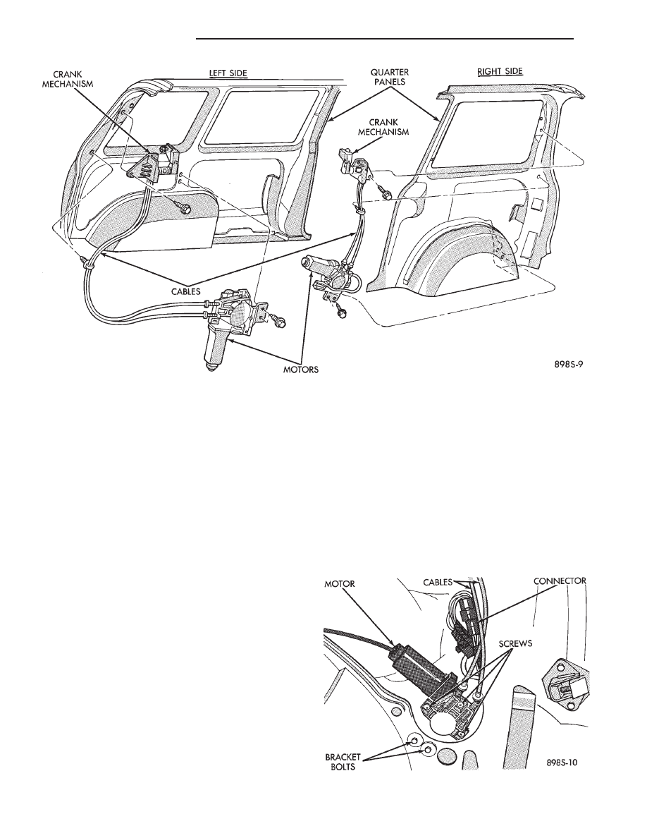
(7) Remove two bolts attaching crank mechanism
to quarter panel (Fig. 10).
(8) Remove three screws attaching cable to motor.
(9) Disengage pivot from quarter glass.
(10) Remove cable retaining clip and remove cable
assembly.
INSTALLATION
(1) Position cable to motor making sure cable pul-
ley engages with motor and install three screws (Fig.
11).
Fig. 10 Motor and Cable Assemblies
Fig. 11 Cable Attaching Screws
8S - 4
POWER WINDOWS
.

(2) Engage pivot to quarter glass.
(3) Install crank mechanism bolts and pull mecha-
nism rearward while tightening (Proper alignment is
required for smooth non-binding operation).
(4) Install cable retaining clip.
(5) Install upper and lower trim panels for the left
side or one piece trim panel right side.
(6) Install B pillar garnish molding and seat belt.
(7) Install side door scuff plate and upper track
cover.
(8) Install front door scuff plate, liftgate scuff
plate, rear seat(s) and windshield side garnish mold-
ing.
VENT WINDOW MOTOR REPLACEMENT
The following procedure describes replacement of a
defective motor without removing the cable assembly
from the vehicle.
REMOVAL
(1) Remove rear quarter trim panel.
(2) Disconnect wiring connector.
(3) Remove three screws attaching motor to cable
(Fig. 11).
(4) Remove two bolts attaching motor bracket to
quarter panel.
(5) Remove motor.
INSTALLATION
(1) Position motor to cable assembly making sure
cable pulley engages with motor and install three
screws.
(2) Install motor bracket to quarter panel bolts.
(3) Connect wiring connector.
(4) Install rear quarter trim panel.
.
POWER WINDOWS
8S - 5

Document Outline
- POWER WINDOWS
Wyszukiwarka
Podobne podstrony:
94AS 8N
ZDMK 8s
94AS 8C
8s inz foto
EZG 8S
LinearAlgebra 2(8s) Nieznany
94AS 8R
94AS 8T
94AS 8H
94AS 22
94AS 25
94AS 8J
94AS 8M
94AS 8A
94AS 8B
exj 8s
94AS IN
Ysaye Sonata No 4 For Violin Solo (Music Score)(8S)
więcej podobnych podstron