
Issued: 04.05.2009
Version: KUKA Servicesteckdose AC110V Einspeisung über Trafo V1 en
KUKA Roboter GmbH
Controller Option
KUKA.Service Socket AC 110 V
For KR C2 edition2005
Installation

© Copyright 2009
KUKA Roboter GmbH
Zugspitzstraße 140
D-86165 Augsburg
Germany
This documentation or excerpts therefrom may not be reproduced or disclosed to third parties without
the express permission of the KUKA Roboter GmbH.
Other functions not described in this documentation may be operable in the controller. The user has
no claims to these functions, however, in the case of a replacement or service work.
We have checked the content of this documentation for conformity with the hardware and software
described. Nevertheless, discrepancies cannot be precluded, for which reason we are not able to
guarantee total conformity. The information in this documentation is checked on a regular basis, how-
ever, and necessary corrections will be incorporated in the subsequent edition.
Subject to technical alterations without an effect on the function.
Translation of the original operating instructions
KIM-PS5-DOC
KUKA.Service Socket AC 110 V
Issued: 04.05.2009 Version: KUKA Servicesteckdose AC110V Einspeisung über Trafo V1 en
Publication:
Pub KUKA.Servicesteckdose AC110V Einspeisung über Trafo en
Book structure: KUKA Servicesteckdose AC110V Einspeisung über Trafo V1.5
Label:
KUKA Servicesteckdose AC110V Einspeisung über Trafo V1

Issued: 04.05.2009 Version: KUKA Servicesteckdose AC110V Einspeisung über Trafo V1 en
Contents
Introduction ..................................................................................................
5
Target group ..............................................................................................................
5
Robot system documentation ....................................................................................
5
Product description .....................................................................................
7
Overview of the robot controller .................................................................................
7
Scope of supply .........................................................................................................
7
Safety ............................................................................................................
9
Representation of warnings and notes ......................................................................
9
Description .................................................................................................................
9
Designated use ..........................................................................................................
9
Personnel ...................................................................................................................
10
Installation ...................................................................................................
11
Preconditions .............................................................................................................
11
Overview ....................................................................................................................
11
Liability .......................................................................................................................
11
Installation ..................................................................................................................
11
Installing the Service Socket AC 110 V ................................................................
11
Installation of power infeed XT 1.1 from transformer AC 110 V ...........................
15
Adhesive labels .....................................................................................................
16
Commissioning .....................................................................................................
17
Removal ................................................................................................................
17
KUKA Service ..............................................................................................
19
Requesting support ....................................................................................................
19
KUKA Customer Support ...........................................................................................
19
Contents


Issued: 04.05.2009 Version: KUKA Servicesteckdose AC110V Einspeisung über Trafo V1 en
1. Introduction
1
Introduction
1.1
Target group
This documentation is aimed at KUKA service and repair personnel. Its use
presupposes the following prior knowledge:
Safety instruction
Electrotechnical training
Advanced knowledge of the robot controller
Personnel
1.2
Robot system documentation
The robot system documentation consists of the following parts:
Operating instructions for the robot
Operating instructions for the robot controller
Operating and programming instructions for the KUKA System Software
Documentation relating to options and accessories
Each of these sets of instructions is a separate document.

Issued: 04.05.2009 Version: KUKA Servicesteckdose AC110V Einspeisung über Trafo V1 en
KUKA.Service Socket AC 110 V
Issued: 04.05.2009 Version: KUKA Servicesteckdose AC110V Einspeisung über Trafo V1 en
2. Product description
2
Product description
2.1
Overview of the robot controller
The following systems are operated with the robot controller:
KUKA robots
KUKA Motion Control
External kinematics
The robot controller consists of the following components:
Control PC
Power unit
KCP teach pendant
Safety logic ESC
KCP coupler (optional)
Service socket (optional)
Connection panel
2.2
Scope of supply
The following components are supplied for installation:
Socket with label
N-type miniature circuit-breaker (4 A), 1-pole
Installation panel for socket
Connecting cables and assembly parts
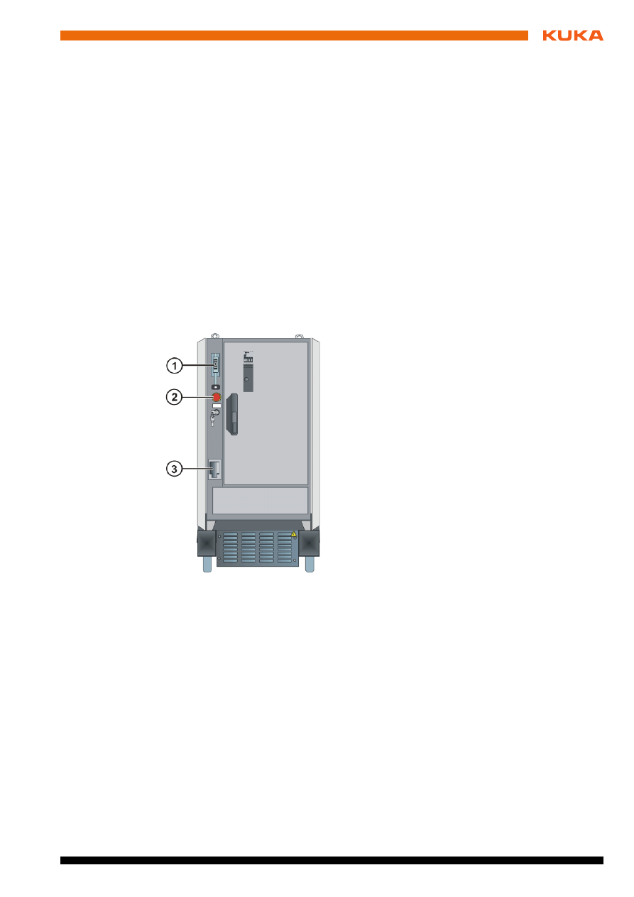
Fig. 2-1: Overview of the robot controller
1
Main switch
2
E-Stop pushbutton
3
Service socket (optional)

Issued: 04.05.2009 Version: KUKA Servicesteckdose AC110V Einspeisung über Trafo V1 en
KUKA.Service Socket AC 110 V
Issued: 04.05.2009 Version: KUKA Servicesteckdose AC110V Einspeisung über Trafo V1 en
3. Safety
3
Safety
3.1
Representation of warnings and notes
Safety
Warnings marked with this pictogram are relevant to safety and must be ob-
served.
Notes
Notes marked with this pictogram contain tips to make your work easier or ref-
erences to further information.
3.2
Description
The service socket must be installed and operated in accordance with the
applicable national laws, regulations and standards.
Overview
Power is supplied to the Service Socket AC 110 V via terminal XT1.1 from
transformer.
3.3
Designated use
Use
The service socket serves as a power supply for test and diagnosis equip-
ment.
Danger!
This warning means that death, severe physical injury or substantial material
damage will occur, if no precautions are taken.
Warning!
This warning means that death, severe physical injury or substantial material
damage may occur, if no precautions are taken.
Caution!
This warning means that minor physical injuries or minor material damage
may occur, if no precautions are taken.
Tips to make your work easier or references to further information.
Danger!
Before installation or removal work is started, it must be ensured that the
power supply cable to the robot controller has been disconnected from the
mains on the plant side. The power supply cable must be deenergized and
secured against being reenergized.
Caution!
The service socket option power infeed via “XT1.1 from transformer” is only
active when the main switch is turned on.
Caution!
A service socket with residual-current circuit-breaker must be selected if
plant regulations or regulations of the power utility concerned stipulate that a
residual-current circuit-breaker is required for socket-outlet circuits.
The residual-current circuit-breaker is tripped by residual currents of 10 mA.
Before installing and connecting the option “Service Socket AC 110 V”,
please refer to the accompanying circuit diagram and cabling description.

Issued: 04.05.2009 Version: KUKA Servicesteckdose AC110V Einspeisung über Trafo V1 en
KUKA.Service Socket AC 110 V
Misuse
Any use or application deviating from the designated use is deemed to be im-
permissible misuse. The manufacturer cannot be held liable for any damage
resulting from such use. The risk lies entirely with the user.
Examples of misuse include:
Operation outside the permissible operating parameters
Connection of power tools
No liability can be accepted if these directions are disregarded.
3.4
Personnel
The operator must meet the following preconditions:
The operator must have read and understood the robot system documen-
tation, including the safety chapter.
The operator must be trained for the work to be carried out.
Work on the robot system must only be carried out by qualified personnel.
These are people who, due to their specialist training, knowledge and ex-
perience, and their familiarization with the relevant standards, are able to
assess the work to be carried out and detect any potential dangers.
Warning!
The socket must not be used as a permanent power source for external de-
vices.
The socket is designed for a load current of max. 4 A.
Issued: 04.05.2009 Version: KUKA Servicesteckdose AC110V Einspeisung über Trafo V1 en
4. Installation
4
Installation
4.1
Preconditions
Necessary
equipment
Standard installation tools, e.g.
Phillips screwdriver
Slotted screwdriver
M6 socket wrench
4.2
Overview
Use
The service socket serves as a power supply for test and diagnosis equip-
ment.
The option “Service Socket AC 110 V without RCCB” is available for integra-
tion into the robot controller.
4.3
Liability
4.4
Installation
4.4.1
Installing the Service Socket AC 110 V
Overview
Caution!
Installation or exchange of this option or individual components thereof may
be performed only by specialist personnel specially trained for this purpose
and acquainted with the risks involved.
These are people who, due to their specialist training, knowledge and expe-
rience, and their familiarization with the relevant standards, are able to as-
sess the work to be carried out and detect any potential dangers.
The specialist personnel must have read and understood the installation in-
structions.
Caution!
Securely tighten all screwed contacts. The wire insulation and the end sleeve
insulation must not be screwed into the contacts.
Detailed information about all connections is contained in the accompanying
circuit diagrams and cabling description.
Issued: 04.05.2009 Version: KUKA Servicesteckdose AC110V Einspeisung über Trafo V1 en
KUKA.Service Socket AC 110 V
Precondition
The main switch is in the OFF position.
Procedure
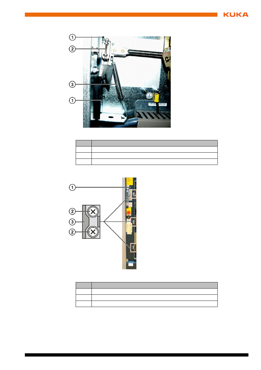
1. Unhook spring.
2. Remove cotter pin.
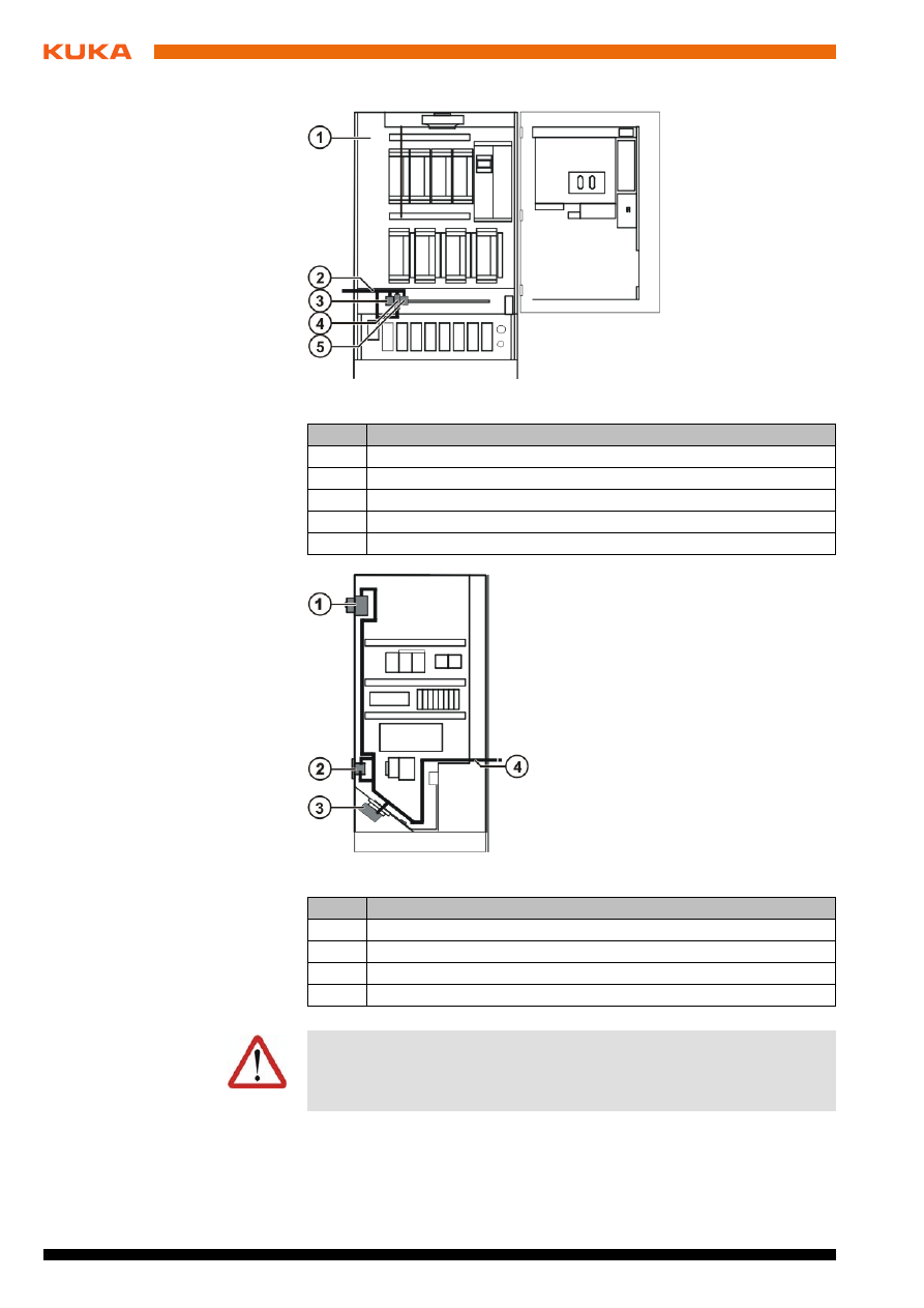
Fig. 4-1: Installation position, front view
Item
Description
1
Mounting panel
2
Cable W108552
3
XT 1.1
4
Miniature circuit-breaker F4
5
Terminal block X3
Fig. 4-2: Installation position, side view
Item
Description
1
Main switch
2
Service socket
3
Power supply connection X1
4
Cable W108552
Warning!
Before installation or removal work is started, it must be ensured that the
power cable to the robot controller is deenergized on the plant side and se-
cured against being reenergized.
Issued: 04.05.2009 Version: KUKA Servicesteckdose AC110V Einspeisung über Trafo V1 en
4. Installation
3. Remove 2 hexagon screws.
4. Remove the 3 locking elements by unscrewing the flat head screws.
5. Remove front panel from the robot controller.
6. Carefully remove the precut mounting aperture in the cabinet wall using a
suitable tool.
Fig. 4-3: Main switch mechanism
Item
Description
1
Hexagon screws
2
Cotter pin
3
Spring
Fig. 4-4: Installation position, locking elements
Item
Description
1
Front plate
2
Flat head screws
3
Locking unit
14 / 27
Issued: 04.05.2009 Version: KUKA Servicesteckdose AC110V Einspeisung über Trafo V1 en
KUKA.Service Socket AC 110 V
7. Deburr the edges of the opening using an appropriate tool.
8. Install the new panel with the cut-out for the socket and fasten the 3 locking
elements.
9. Remove wire F4/2 of cable W108552 from miniature circuit-breaker F4.
10. Remove wire X3/1 from terminal block X3.
11. From the outside, push the loose ends of the socket connections through
the opening that has just been created until the service socket is seated in
the opening.
12. Insert a small screwdriver into the lower opening and lift the plastic cover
of the service socket forwards and outwards.
13. Tighten the 3 screws that are now visible by turning them clockwise to
bring the terminals mounted on the back into the correct position and
clamp them firmly in place between the metal panel and the service sock-
et.
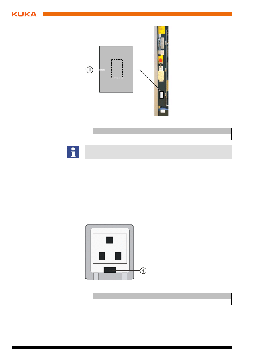
Fig. 4-5: Installation position, front panel
Item
Description
1
Precut cover plate
Prevent metal chips from entering the interior of the robot controller when
knocking out the cover plate.
Fig. 4-6: X01
Item
Description
1
Opening
Issued: 04.05.2009 Version: KUKA Servicesteckdose AC110V Einspeisung über Trafo V1 en
4. Installation
14. Push the plastic cover back into position – it must click audibly into posi-
tion.
15. Close the cover flap of the service socket.
Installation of the service socket into the frame of the robot controller is now
complete.
4.4.2
Installation of power infeed XT 1.1 from transformer AC 110 V
The scope of supply of the “Service Socket AC 110 V from Transformer” in-
cludes flush-mounting miniature circuit-breaker F4, terminal block X3 and the
cable W108552.
1. Reinstall the main switch by reversing the above sequence.
2. Snap miniature circuit-breaker F4 and terminal block X3 with retaining clip
onto the bottommost top-hat rail in the robot controller, to the right of ter-
minals XT1.1.
3. Connect wire XT1.1/V21 from terminal XT1.1 to terminal X3/1 from below.
4. Connect wire XT1.1/U21 from terminal XT1.1 to terminal 1 of miniature cir-
cuit-breaker F4.
5. Route the wires of the socket connection along the left cable harness to
miniature circuit-breaker F4.
6. Reconnect wire F4/2, that was disconnected before the installation, to ter-
minal 2 of miniature circuit-breaker F4.
7. Connect wire X3/1 from X01/N to top of terminal X3/1.
8. Connect ground conductor from X01/PE to top of X3/3.
9. Check installation against the connection diagram (
>>>
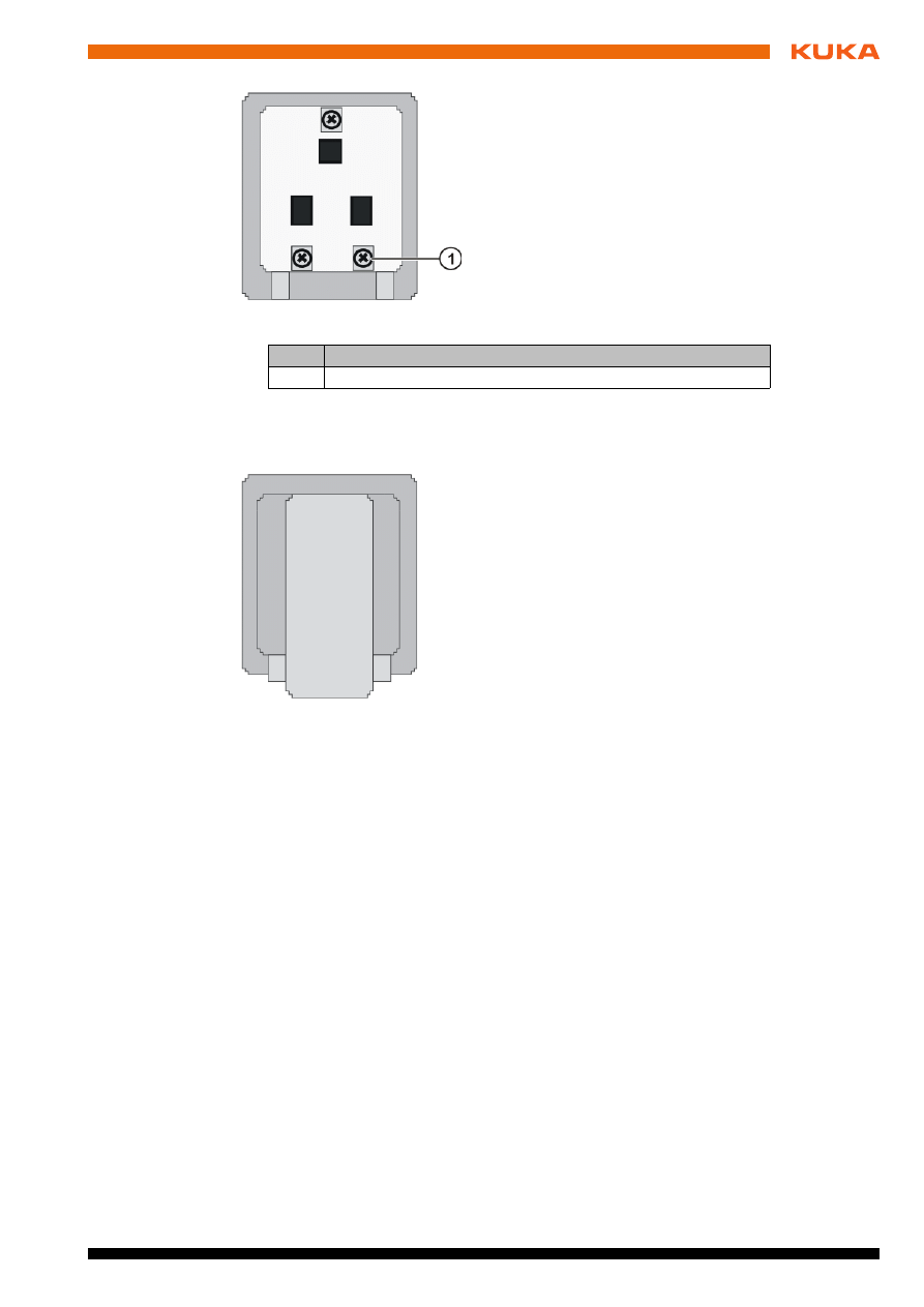
Fig. 4-7: X01
Item
Description
1
Screw
Fig. 4-8: X01 with cover flap
16 / 27
Issued: 04.05.2009 Version: KUKA Servicesteckdose AC110V Einspeisung über Trafo V1 en
KUKA.Service Socket AC 110 V
4.4.3
Adhesive labels
Affix adhesive labels to the housing above terminal block F4 and miniature cir-
cuit-breaker X3.
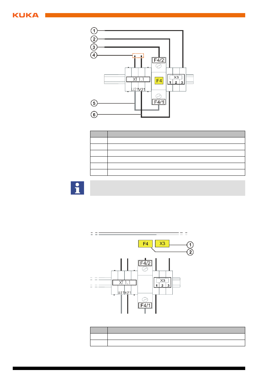
Fig. 4-9: XT1.1 connection diagram
Item
Description
1
Ground conductor from terminal X3/3 to X01/PE
2
Wire X3/1 from terminal X3/1 to connector X01/N
3
Wire F4/2 from terminal F4/2 to connector X01/L
4
Power supply via transformer
5
Individual wire from XT1.1/U21 to terminal F4/1
6
Individual wire from XT1.1/V21 to terminal X3/1
With the option XT 1.1 “Power supply via transformer”, the service socket
is only active when the main switch is turned on.
Fig. 4-10: Adhesive labels
Item
Description
1
Adhesive label X3
2
Adhesive label F4
Issued: 04.05.2009 Version: KUKA Servicesteckdose AC110V Einspeisung über Trafo V1 en
4. Installation
4.4.4
Commissioning
After carrying out a visual inspection, reconnect the robot controller to the
mains supply and turn on the main switch.
Once these tasks have been completed, the Service Socket AC 110 V from
Transformer is ready for operation.
4.4.5
Removal
Precondition
The main switch is in the OFF position.
Remove the Service Socket before Main Switch by reversing the installation
procedure.
(
>>>
4.4.1 "Installing the Service Socket AC 110 V" page 11)
Before turning on the main power switch, check that all of the cables and
screws are correctly fitted and securely fastened.
Warning!
The cabinet may only be operated with the supply voltage specified on the
rating plate.
Caution!
After turning on the main switch, check the control cabinet housing for off-
set voltage using a suitable test device.
Test the function of the Service Socket AC 110 V from Transformer using
a suitable test device.
Warning!
Before installation or removal work is started, it must be ensured that the in-
coming power cable is deenergized and that measures have been taken to
prevent it from being inadvertently energized again.

18 / 27
Issued: 04.05.2009 Version: KUKA Servicesteckdose AC110V Einspeisung über Trafo V1 en
KUKA.Service Socket AC 110 V

Issued: 04.05.2009 Version: KUKA Servicesteckdose AC110V Einspeisung über Trafo V1 en
5. KUKA Service
5
KUKA Service
5.1
Requesting support
Introduction
The KUKA Roboter GmbH documentation offers information on operation and
provides assistance with troubleshooting. For further assistance, please con-
tact your local KUKA subsidiary.
Information
The following information is required for processing a support request:
Model and serial number of the robot
Model and serial number of the controller
Model and serial number of the linear unit (if applicable)
Version of the KUKA System Software
Optional software or modifications
Archive of the software
Application used
Any external axes used
Description of the problem, duration and frequency of the fault
5.2
KUKA Customer Support
Availability
KUKA Customer Support is available in many countries. Please do not hesi-
tate to contact us if you have any questions.
Argentina
Ruben Costantini S.A. (Agency)
Luis Angel Huergo 13 20
Parque Industrial
2400 San Francisco (CBA)
Argentina
Tel. +54 3564 421033
Fax +54 3564 428877
ventas@costantini-sa.com
Australia
Marand Precision Engineering Pty. Ltd. (Agency)
153 Keys Road
Moorabbin
Victoria 31 89
Australia
Tel. +61 3 8552-0600
Fax +61 3 8552-0605
robotics@marand.com.au
Faults leading to production downtime should be reported to the local KUKA
subsidiary within one hour of their occurrence.

Issued: 04.05.2009 Version: KUKA Servicesteckdose AC110V Einspeisung über Trafo V1 en
KUKA.Service Socket AC 110 V
Belgium
KUKA Automatisering + Robots N.V.
Centrum Zuid 1031
3530 Houthalen
Belgium
Tel. +32 11 516160
Fax +32 11 526794
info@kuka.be
www.kuka.be
Brazil
KUKA Roboter do Brasil Ltda.
Avenida Franz Liszt, 80
Parque Novo Mundo
Jd. Guançã
CEP 02151 900 São Paulo
SP Brazil
Tel. +55 11 69844900
Fax +55 11 62017883
info@kuka-roboter.com.br
Chile
Robotec S.A. (Agency)
Santiago de Chile
Chile
Tel. +56 2 331-5951
Fax +56 2 331-5952
robotec@robotec.cl
www.robotec.cl
China
KUKA Flexible Manufacturing Equipment (Shanghai) Co., Ltd.
Shanghai Qingpu Industrial Zone
No. 502 Tianying Rd.
201712 Shanghai
P.R. China
Tel. +86 21 5922-8652
Fax +86 21 5922-8538
Franz.Poeckl@kuka-sha.com.cn
www.kuka.cn
Germany
KUKA Roboter GmbH
Zugspitzstr. 140
86165 Augsburg
Germany
Tel. +49 821 797-4000
Fax +49 821 797-1616
info@kuka-roboter.de
www.kuka-roboter.de

Issued: 04.05.2009 Version: KUKA Servicesteckdose AC110V Einspeisung über Trafo V1 en
5. KUKA Service
France
KUKA Automatisme + Robotique SAS
Techvallée
6, Avenue du Parc
91140 Villebon S/Yvette
France
Tel. +33 1 6931660-0
Fax +33 1 6931660-1
commercial@kuka.fr
www.kuka.fr
India
KUKA Robotics, Private Limited
621 Galleria Towers
DLF Phase IV
122 002 Gurgaon
Haryana
India
Tel. +91 124 4148574
info@kuka.in
www.kuka.in
Italy
KUKA Roboter Italia S.p.A.
Via Pavia 9/a - int.6
10098 Rivoli (TO)
Italy
Tel. +39 011 959-5013
Fax +39 011 959-5141
kuka@kuka.it
www.kuka.it
Japan
KUKA Robotics Japan K.K.
Ogikubo TM Building 7F
5-26-13 Ogikubo, Suginami-ku
Tokio
167-0051
Japan
Tel. +81 353 47-9831
Fax +81 353 47-9835
kuka.co.jp
Korea
KUKA Robot Automation Korea Co. Ltd.
4 Ba 806 Sihwa Ind. Complex
Sung-Gok Dong, Ansan City
Kyunggi Do
425-110
Korea
Tel. +82 31 496-9937 or -9938
Fax +82 31 496-9939
info@kukakorea.com

22 / 27
Issued: 04.05.2009 Version: KUKA Servicesteckdose AC110V Einspeisung über Trafo V1 en
KUKA.Service Socket AC 110 V
Malaysia
KUKA Robot Automation Sdn Bhd
South East Asia Regional Office
No. 24, Jalan TPP 1/10
Taman Industri Puchong
47100 Puchong
Selangor
Malaysia
Tel. +60 3 8061-0613 or -0614
Fax +60 3 8061-7386
info@kuka.com.my
Mexico
KUKA de Mexico S. de R.L. de C.V.
Rio San Joaquin #339, Local 5
Colonia Pensil Sur
C.P. 11490 Mexico D.F.
Mexico
Tel. +52 55 5203-8407
Fax +52 55 5203-8148
info@kuka.com.mx
Norway
KUKA Sveiseanlegg + Roboter
Bryggeveien 9
2821 Gjövik
Norway
Tel. +47 61 133422
Fax +47 61 186200
geir.ulsrud@kuka.no
Austria
KUKA Roboter Austria GmbH
Vertriebsbüro Österreich
Regensburger Strasse 9/1
4020 Linz
Austria
Tel. +43 732 784752
Fax +43 732 793880
office@kuka-roboter.at
www.kuka-roboter.at
Portugal
KUKA Sistemas de Automatización S.A.
Rua do Alto da Guerra n° 50
Armazém 04
2910 011 Setúbal
Portugal
Tel. +351 265 729780
Fax +351 265 729782
kuka@mail.telepac.pt

Issued: 04.05.2009 Version: KUKA Servicesteckdose AC110V Einspeisung über Trafo V1 en
5. KUKA Service
Russia
OOO KUKA Robotics Rus
Webnaja ul. 8A
107143 Moskau
Russia
Tel. +7 495 781-31-20
Fax +7 495 781-31-19
kuka-robotics.ru
Sweden
KUKA Svetsanläggningar + Robotar AB
A. Odhners gata 15
421 30 Västra Frölunda
Sweden
Tel. +46 31 7266-200
Fax +46 31 7266-201
info@kuka.se
Switzerland
KUKA Roboter Schweiz AG
Riedstr. 7
8953 Dietikon
Switzerland
Tel. +41 44 74490-90
Fax +41 44 74490-91
info@kuka-roboter.ch
www.kuka-roboter.ch
Spain
KUKA Sistemas de Automatización S.A.
Pol. Industrial
Torrent de la Pastera
Carrer del Bages s/n
08800 Vilanova i la Geltrú (Barcelona)
Spain
Tel. +34 93 814-2353
Fax +34 93 814-2950
Comercial@kuka-e.com
www.kuka-e.com
South Africa
Jendamark Automation LTD (Agency)
76a York Road
North End
6000 Port Elizabeth
South Africa
Tel. +27 41 391 4700
Fax +27 41 373 3869
www.jendamark.co.za

24 / 27
Issued: 04.05.2009 Version: KUKA Servicesteckdose AC110V Einspeisung über Trafo V1 en
KUKA.Service Socket AC 110 V
Taiwan
KUKA Robot Automation Taiwan Co. Ltd.
136, Section 2, Huanjung E. Road
Jungli City, Taoyuan
Taiwan 320
Tel. +886 3 4371902
Fax +886 3 2830023
info@kuka.com.tw
www.kuka.com.tw
Thailand
KUKA Robot Automation (M)SdnBhd
Thailand Office
c/o Maccall System Co. Ltd.
49/9-10 Soi Kingkaew 30 Kingkaew Road
Tt. Rachatheva, A. Bangpli
Samutprakarn
10540 Thailand
Tel. +66 2 7502737
Fax +66 2 6612355
atika@ji-net.com
www.kuka-roboter.de
Hungary
KUKA Robotics Hungaria Kft.
Fö út 140
2335 Taksony
Hungary
Tel. +36 24 501609
Fax +36 24 477031
info@kuka-robotics.hu
USA
KUKA Robotics Corp.
22500 Key Drive
Clinton Township
48036 Michigan
USA
Tel. +1 866 8735852
Fax +1 586 5692087
info@kukarobotics.com
www.kukarobotics.com
UK
KUKA Automation + Robotics
Hereward Rise
Halesowen
B62 8AN
UK
Tel. +44 121 585-0800
Fax +44 121 585-0900
sales@kuka.co.uk

25 / 27
Issued: 04.05.2009 Version: KUKA Servicesteckdose AC110V Einspeisung über Trafo V1 en
Index
Index
C
Commissioning 17
Connection panel 7
Control PC 7
D
Description 9
Designated use 9
Documentation, robot system 5
I
Installation 11
Installation position, front view 12
Installation position, side view 12
Installation, power infeed from transformer AC
110 V 15
Installation, Service Socket AC 110 V 11
Introduction 5
O
Overview 11
Overview of the robot controller 7
P
Power unit 7
Preconditions 11
Product description 7
S
Safety 9
Safety instructions 9
Safety logic 7
Scope of supply 7
Service Socket AC 110 V, installation 11
Service, KUKA Roboter 19
Support request 19


Issued: 04.05.2009 Version: KUKA Servicesteckdose AC110V Einspeisung über Trafo V1 en
KUKA.Service Socket AC 110 V
Document Outline
- KUKA.Service Socket AC 110 V
- 1 Introduction
- 2 Product description
- 3 Safety
- 4 Installation
- 4.1 Preconditions
- 4.2 Overview
- 4.3 Liability
- 4.4 Installation
- 5 KUKA Service
- Index
Wyszukiwarka
Podobne podstrony:
KUKA Service Socket AC230V with FI en
kuka sim V1 1 en
KUKA Load 50 en
KUKA RSI, serSensor kss51 en
KUKA RSI rsi r20 en id 744255 Nieznany
KUKA LOAD 32 en
KST KUKA Encryption 12 en
kenwood ke 205 service en
Sony TC WR770 TC WR875 service en
Red Hat Enterprise Linux 6 Managing Confined Services en US
FG Update Service Pro EN 1232 3702 3
KST KUKA Encryption 11 en
hfe technics sb 5000 6000 service en (1)
KUKA Router en
hfe technics sb e100 service en
Service book R75 EN
Prezentacja firmy MARSTATE SERVICE BHP PPOZ PPT
więcej podobnych podstron