
Issued: 13.05.2009
Version: KUKA.Load 3.2 V1 en
KUKA Roboter GmbH
Software
KUKA.Load 3.2
Operating Instructions

© Copyright 2009
KUKA Roboter GmbH
Zugspitzstraße 140
D-86165 Augsburg
Germany
This documentation or excerpts therefrom may not be reproduced or disclosed to third parties without
the express permission of the KUKA Roboter GmbH.
Other functions not described in this documentation may be operable in the controller. The user has
no claims to these functions, however, in the case of a replacement or service work.
We have checked the content of this documentation for conformity with the hardware and software
described. Nevertheless, discrepancies cannot be precluded, for which reason we are not able to
guarantee total conformity. The information in this documentation is checked on a regular basis, how-
ever, and necessary corrections will be incorporated in the subsequent edition.
Subject to technical alterations without an effect on the function.
Translation of the original operating instructions
KIM-PS5-DOC
KUKA.Load 3.2
2 / 29
Issued: 13.05.2009 Version: KUKA.Load 3.2 V1 en
Publication:
Pub KUKA.Load 3.2 en
Book structure: KUKA.Load 3.2 V1.1
Label:
KUKA.Load 3.2 V1

3 / 29
Issued: 13.05.2009 Version: KUKA.Load 3.2 V1 en
Contents
Introduction ..................................................................................................
5
Target group ..............................................................................................................
5
Representation of warnings and notes ......................................................................
5
Trademarks ................................................................................................................
5
Product description .....................................................................................
7
Overview of KUKA.Load ............................................................................................
7
Load data ...................................................................................................................
7
Loads on the robot ................................................................................................
8
Static overloading of the robot ..............................................................................
9
Dynamic overloading of the robot .........................................................................
9
Installation ...................................................................................................
11
System requirements .................................................................................................
11
Installing KUKA.Load .................................................................................................
11
Uninstalling KUKA.Load .............................................................................................
11
Operation ......................................................................................................
13
Starting KUKA.Load ...................................................................................................
13
User interface for KUKA.Load ....................................................................................
13
Creating a new project ...............................................................................................
14
Determining the robot for the payload ........................................................................
14
Verifying the loads on the robot .................................................................................
15
Using the Sum Up Tools function ..............................................................................
16
Saving the robot in the project ...................................................................................
17
Opening the robot from the project ............................................................................
17
Creating the Sign Off Sheet .......................................................................................
17
KUKA Service ..............................................................................................
21
Requesting support ....................................................................................................
21
KUKA Customer Support ...........................................................................................
21
Contents


5 / 29
Issued: 13.05.2009 Version: KUKA.Load 3.2 V1 en
1. Introduction
1
Introduction
1.1
Target group
This documentation is aimed at users with the following knowledge and skills:
Knowledge of robotics
Advanced knowledge of dynamic and static loading on the robot
1.2
Representation of warnings and notes
Safety
Warnings marked with this pictogram are relevant to safety and must be ob-
served.
Notes
Notes marked with this pictogram contain tips to make your work easier or ref-
erences to further information.
1.3
Trademarks
Windows is a trademark of Microsoft Corporation.
Excel is a trademark of Microsoft Corporation.
Danger!
This warning means that death, severe physical injury or substantial material
damage will occur, if no precautions are taken.
Warning!
This warning means that death, severe physical injury or substantial material
damage may occur, if no precautions are taken.
Caution!
This warning means that minor physical injuries or minor material damage
may occur, if no precautions are taken.
Tips to make your work easier or references to further information.

7 / 29
Issued: 13.05.2009 Version: KUKA.Load 3.2 V1 en
2. Product description
2
Product description
2.1
Overview of KUKA.Load
Functions
KUKA.Load is a software product with the following functions:
Verifying a load situation:
Verfying a robot for a given load
Selecting a robot for a given load
Calculating the load for several tools mounted simultaneously on the
flange
Generating a message in the event of static overloading
Generating a message in the event of dynamic overloading
Creating acceptance reports (Sign Off Sheets)
Managing projects with a number of robots
Data transfer to Excel (form is write-protected)
Description
2.2
Load data
The load data are factored into the calculation of the paths and accelerations
and help to optimize the cycle times. The load data must be entered in the ro-
bot controller.
General process forces cannot be taken into consideration by the software.
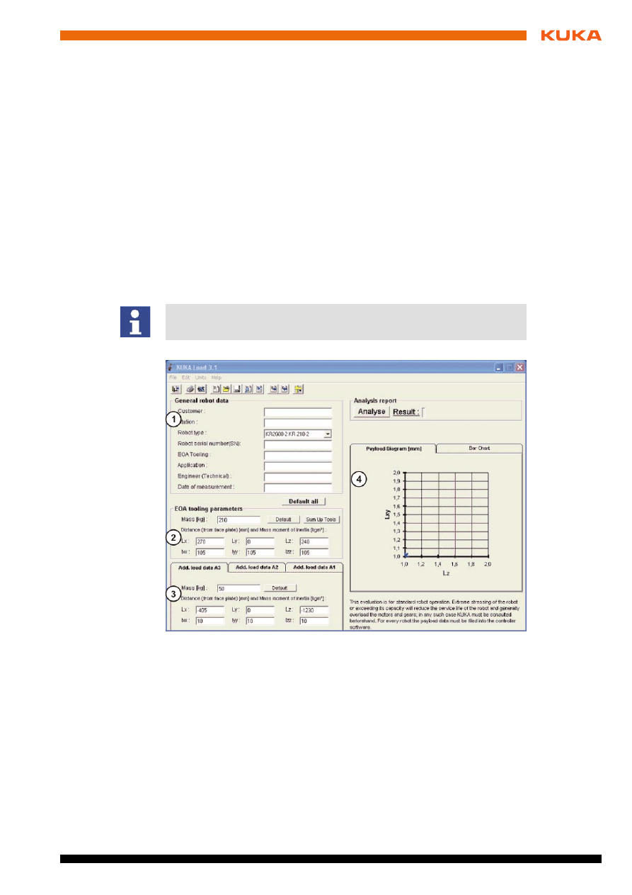
Fig. 2-1: KUKA.Load user interface
1
Data entry fields for customer details and robot type
2
Data entry fields for payloads on the flange
3
Tabs for supplementary loads A1, A2, A3
4
Calculated load data diagram
8 / 29
Issued: 13.05.2009 Version: KUKA.Load 3.2 V1 en
KUKA.Load 3.2
2.2.1
Loads on the robot
Description
Various loads can be mounted on the robot:
Payload on the flange
Supplementary load on axis 3
Supplementary load on axis 2
Supplementary load on axis 1
All loads added together give the overall load.
Parameters
The load data are defined using the following parameters:
Warning!
If a robot is operated with incorrect load data or an unsuitable load, this can
result in danger to life and limb and/or substantial material damage to the ro-
bot system.
There is a payload diagram for every robot. It can be used to check quickly
whether the payload could be suitable for the robot. The diagram is not, how-
ever, a substitute for checking the payload with KUKA.Load.
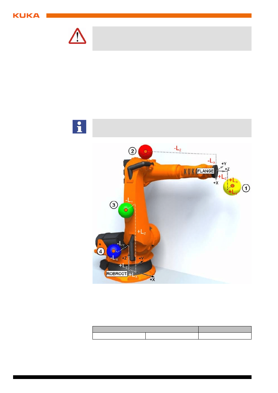
Fig. 2-2: Loads on the robot
1
Payload
3
Supplementary load on axis 2
2
Supplementary load on axis 3
4
Supplementary load on axis 1
Parameter
Unit
Mass
m
kg

9 / 29
Issued: 13.05.2009 Version: KUKA.Load 3.2 V1 en
2. Product description
Reference systems of the X, Y and Z values for each load:
Sources
Load data can be obtained from the following sources:
Software option KUKA.LoadDetect (only for payloads)
Manufacturer information
Manual calculation
CAD programs
2.2.2
Static overloading of the robot
Description
If the permissible motor braking torques or the motor holding torques under
servo control are exceeded while the robot is at a standstill, this is referred to
as static overloading of the robot. This overloading can be prevented by
means of the following measures:
Shifting the position of the center of gravity towards the flange center point
Using a robot with a higher rated payload
Reducing the mass/weight
2.2.3
Dynamic overloading of the robot
Description
If the maximum permissible kinetic energy values are exceeded by means of
excessive mass moments of inertia, this is referred to as dynamic overloading
of the robot. This overloading can be prevented by means of the following
measures:
Reduce the mass moments of inertia by:
Using a more geometrically compact load
Reducing the mass
Using a robot with a higher rated payload
Distance to the center
of gravity
L
x
, L
y
, L
z
mm
Mass moments of iner-
tia at the center of
gravity
I
xx
, I
yy
, I
zz
kg m
2
Load
Reference system
Supplementary load
A1
ROBROOT coordinate system
A1 = 0°
Supplementary load
A2
ROBROOT coordinate system
A2 = -90°
Supplementary load
A3
FLANGE coordinate system
A4 = 0°, A5 = 0°, A6 = 0°
Payload
FLANGE coordinate system
Parameter
Unit
KUKA Roboter GmbH must always be consulted in the case of overloading.
(
>>>
5 "KUKA Service" page 21)
KUKA Roboter GmbH must always be consulted in the case of overloading.
(
>>>
5 "KUKA Service" page 21)


11 / 29
Issued: 13.05.2009 Version: KUKA.Load 3.2 V1 en
3. Installation
3
Installation
3.1
System requirements
Hardware
PC with Pentium processor, min. 166 GHz
512 MB RAM
Graphics card with a resolution of at least 800 x 600 pixels
Software
Windows 95, WinNT
Windows 2000 or Windows XP
Microsoft Excel 97 or higher for:
Sign Off Sheet
Project creation
3.2
Installing KUKA.Load
Precondition
Local administrator rights on the PC
All Windows applications currently running must be closed.
Any existing versions of KUKA.Load must be uninstalled. Updating without
uninstallation is not possible.
Procedure
1. Download KUKA.Load free of charge from the KUKA website www.ku-
2. Start the Setup program.
3. Press OK to continue.
4. If required, change the installation directory with Change Directory.
5. Click on
to start the installation.
3.3
Uninstalling KUKA.Load
Precondition
Local administrator rights on the PC
All Windows applications currently running must be closed.
Procedure
1. Click on Control Panel in the Windows Start menu.
2. Click on Software.
3. Select KUKA.Load from the list.
4. Click on Change/Remove to uninstall the software.
Warning!
The software must not be installed on the robot controller.

13 / 29
Issued: 13.05.2009 Version: KUKA.Load 3.2 V1 en
4. Operation
4
Operation
4.1
Starting KUKA.Load
Procedure
Start the program via the menu sequence Start > Programs > KUKA >
KUKA_Load.
4.2
User interface for KUKA.Load
Description
Description
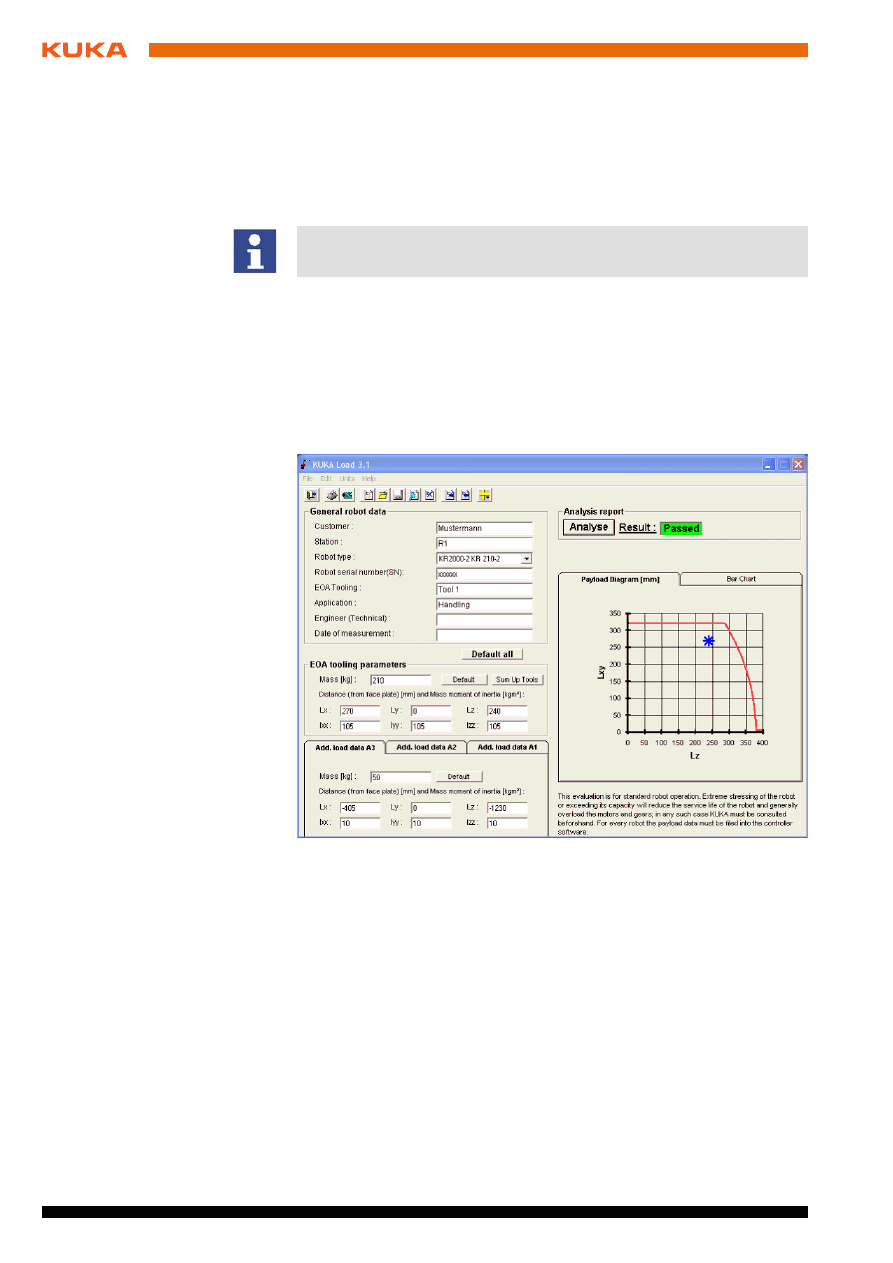
Fig. 4-1: KUKA.Load user interface
1
Data entry fields for customer details and robot type
2
Data entry fields for payloads on the flange
3
Tabs for supplementary loads A1, A2, A3
4
Calculated load data diagram
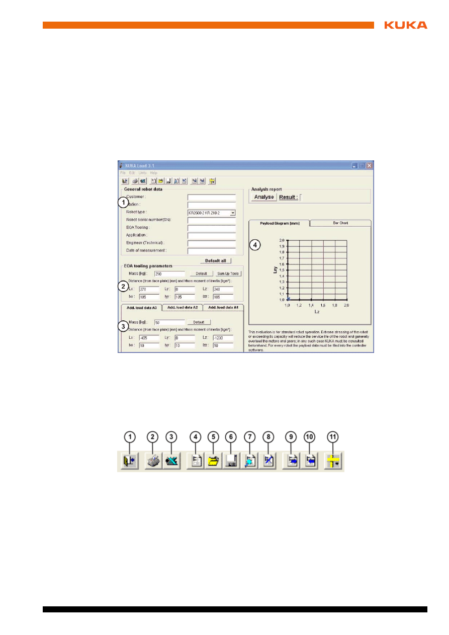
Fig. 4-2: KUKA.Load toolbar
1
Exit program
2
Print current load data with the default printer
3
Create acceptance report (Sign Off Sheet in Excel)
4
Create new project
5
Open project
6
Save project
7
Display current project (Excel table)
8
Close current project (Excel table)
9
Open robot from current project

14 / 29
Issued: 13.05.2009 Version: KUKA.Load 3.2 V1 en
KUKA.Load 3.2
4.3
Creating a new project
Description
A KUKA.Load project can be used to manage and verify the load data for a
number of robots. The project is a write-protected Excel file.
Procedure
1. Create a new project using the menu sequence File > New.
2. Enter the customer details in the General data window and select the
measurement system.
3. Press OK to continue.
Now the analysis of the load data can be started.
4.4
Determining the robot for the payload
Precondition
Load data are known.
Procedure
1. In the General robot data area enter the statistical data (customer, serial
number, etc.).
2. Select the type of robot in the General robot data area under Robot type.
3. Click on the button Default all to reset all values of the robot type.
4. Enter the values for the payload in the area EOA tooling parameters:
Mass
Distance to the center of gravity (L
X
, L
Y
, L
Z
)
Mass moment of inertia at the center of gravity (I
XX
, I
YY
, I
ZZ
)
5. Enter the values for the supplementary loads in the tabs Add. load data
A1... A3:
Mass
Distance to the center of gravity (L
X
, L
Y
, L
Z
)
Mass moment of inertia at the center of gravity (I
XX
, I
YY
, I
ZZ
)
6. Click on the Analyse button to verify the load data.
The result is displayed in the Analysis report area.
If the load data entered are permissible for the selected robot, the result
Passed is displayed:
The robot selected is suitable for the specified load data.
If the selected robot is not suitable for the specified load data, a static overload
is shown in the payload diagram and/or a static/dynamic overload is shown in
the bar chart.
10
Add robot to current project
11
Select measurement system
After analysis and project data entry, always save KUKA.Load before clos-
ing. New analyses are not automatically saved in an open project.
If more than one component is mounted on the flange at the same time, use
the Sum Up Tools function.
Fig. 4-3: KUKA.Load Analysis report
15 / 29
Issued: 13.05.2009 Version: KUKA.Load 3.2 V1 en
4. Operation
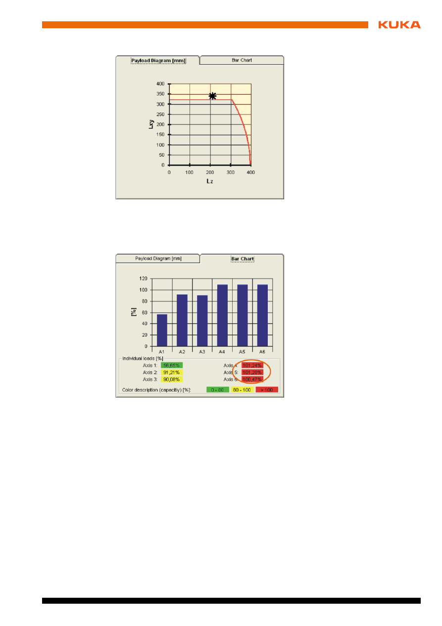
Payload diagram:
The calculated point lies outside the limits of the payload diagram. The ro-
bot is statically overloaded.
Bar chart:
Axes A4 - A6 exceed the 100% limit of the bar chart. The robot is statically
and/or dynamically overloaded.
If the selected robot is not suitable:
1. Select a different type of robot in the General robot data area under Ro-
bot type.
2. Click on the Analyse button to verify the load data.
In the event of repeated negative results, please consult the KUKA Roboter
GmbH.
4.5
Verifying the loads on the robot
Precondition
Load data are known.
Procedure
1. In the General robot data area enter the statistical data (customer, serial
number, etc.).
Fig. 4-4: KUKA.Load payload diagram
Fig. 4-5: KUKA.Load bar chart
16 / 29
Issued: 13.05.2009 Version: KUKA.Load 3.2 V1 en
KUKA.Load 3.2
2. Select the type of robot in the General robot data area under Robot type.
3. Click on the button Default all to reset all values of the robot type.
4. Enter the values for the payload in the area EOA tooling parameters:
Mass
Distance to the center of gravity (L
X
, L
Y
, L
Z
)
Mass moment of inertia at the center of gravity (I
XX
, I
YY
, I
ZZ
)
5. Enter the values for the supplementary loads in the tabs Add. load data
A1... A3:
Mass
Distance to the center of gravity (L
X
, L
Y
, L
Z
)
Mass moment of inertia at the center of gravity (I
XX
, I
YY
, I
ZZ
)
6. Click on the Analyse button to verify the load data.
The result is displayed.
4.6
Using the Sum Up Tools function
The Sum Up Tools function can be used to calculate the total load from the
known values of a number of components mounted simultaneously on the
flange (e.g. tool and workpiece). For this, the data for each component are en-
tered separately.
Procedure
1. Click on the Sum Up Tools button.
The Tool Summation dialog appears.
If more than one component is mounted on the flange at the same time, use
the Sum Up Tools function.
Fig. 4-6: KUKA.Load with payload diagram (result)

17 / 29
Issued: 13.05.2009 Version: KUKA.Load 3.2 V1 en
4. Operation
2. Enter the values for the payload in the Single Tool Data area:
Mass
Distance to the center of gravity (L
X
, L
Y
, L
Z
)
Mass moment of inertia at the center of gravity (I
XX
, I
YY
, I
ZZ
)
3. Add the values to the list using the Add Tool Data button.
The values appear in the window area.
4. Repeat steps 2 and 3 for the next component.
5. When all the values are displayed in the window, start the calculation with
OK.
The total load is calculated.
4.7
Saving the robot in the project
Precondition
Project is created and open.
The payload has been verified.
Procedure
1. Select the menu sequence Edit > Add Robot to open the dialog Save
current payload data record.
2. Enter or accept the serial number of the robot and the customer details.
3. Use the Save button to save the data set in the project.
4.8
Opening the robot from the project
Precondition
The project is open.
Procedure
1. Select the menu sequence Edit > Choose Robot to open the dialog
Choose robot to analyse.
2. Select the robot via the serial number and continue with OK.
4.9
Creating the Sign Off Sheet
Precondition
Project is created and open.
The payload has been verified.
Procedure
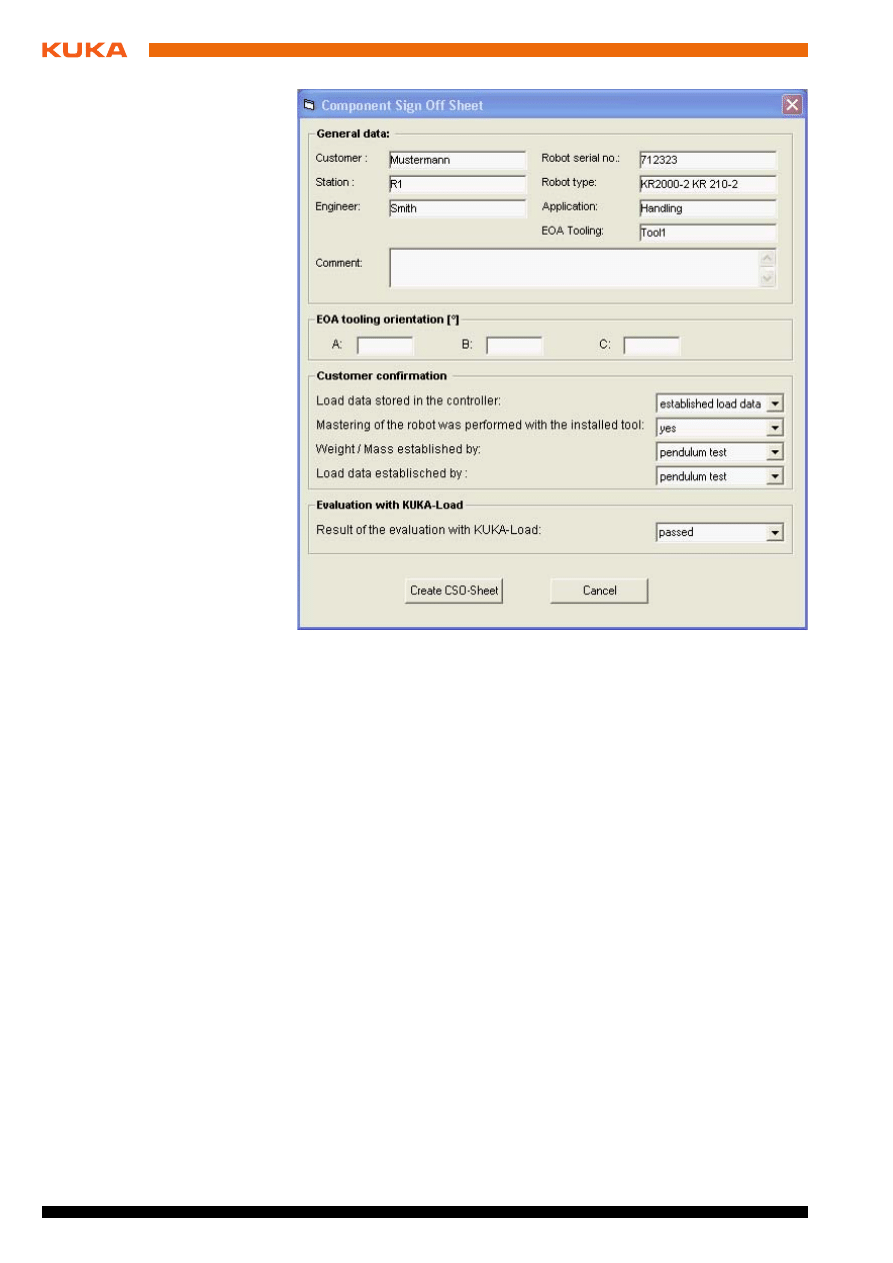
1. Select the menu sequence Edit > Sign Off Sheet to open the dialog Com-
ponent Sign Off Sheet.
Fig. 4-7: KUKA.Load, Tool Summation dialog
18 / 29
Issued: 13.05.2009 Version: KUKA.Load 3.2 V1 en
KUKA.Load 3.2
2. Enter or accept the serial number of the robot and the customer details.
3. Optionally: Enter the orientation of the principal inertia axes of the center
of gravity in the EOA tooling orientation area.
4. Select the following options in the Customer confirmation area:
Load data saved in the controller:
Correct load data entered
Work with standard settings
Robot mastered:
Yes
No
Weight / mass established by:
Measured
Determined with KUKA.LoadDetect
Calculated
Load data established by:
Measured
Determined with KUKA.LoadDetect
Calculated
5. Create the Component Sign Off Sheet using the button Create CSO-
Sheet.
Fig. 4-8: KUKA.Load, Sign Off Sheet dialog
19 / 29
Issued: 13.05.2009 Version: KUKA.Load 3.2 V1 en
4. Operation
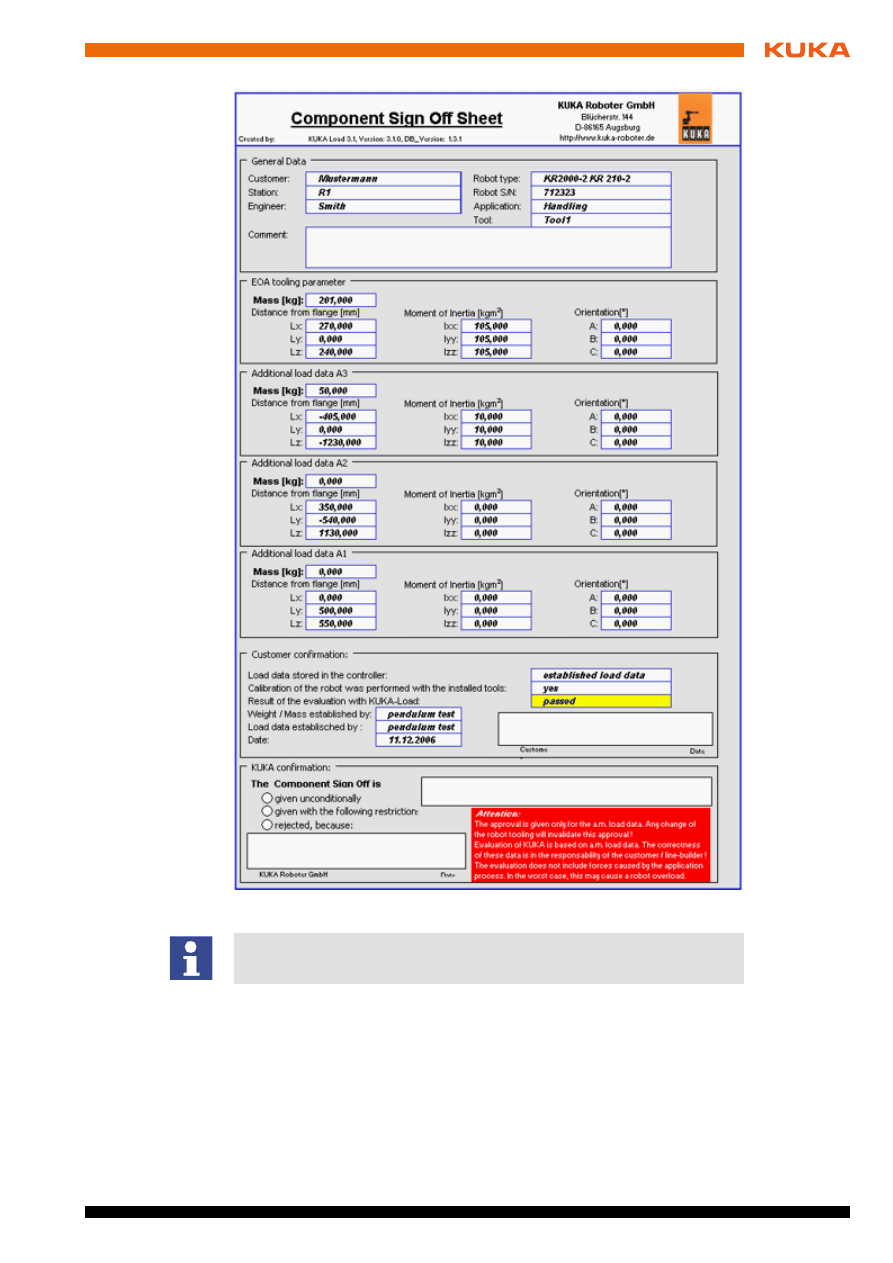
Fig. 4-9: KUKA.Load Sign Off Sheet
When submitting the Sign Off Sheet for checking by the KUKA Roboter Gm-
bH, please always include the project database (Excel).


21 / 29
Issued: 13.05.2009 Version: KUKA.Load 3.2 V1 en
5. KUKA Service
5
KUKA Service
5.1
Requesting support
Introduction
The KUKA Roboter GmbH documentation offers information on operation and
provides assistance with troubleshooting. For further assistance, please con-
tact your local KUKA subsidiary.
Information
The following information is required for processing a support request:
Model and serial number of the robot
Model and serial number of the controller
Model and serial number of the linear unit (if applicable)
Version of the KUKA System Software
Optional software or modifications
Archive of the software
Application used
Any external axes used
Description of the problem, duration and frequency of the fault
5.2
KUKA Customer Support
Availability
KUKA Customer Support is available in many countries. Please do not hesi-
tate to contact us if you have any questions.
Argentina
Ruben Costantini S.A. (Agency)
Luis Angel Huergo 13 20
Parque Industrial
2400 San Francisco (CBA)
Argentina
Tel. +54 3564 421033
Fax +54 3564 428877
ventas@costantini-sa.com
Australia
Marand Precision Engineering Pty. Ltd. (Agency)
153 Keys Road
Moorabbin
Victoria 31 89
Australia
Tel. +61 3 8552-0600
Fax +61 3 8552-0605
robotics@marand.com.au
Faults leading to production downtime should be reported to the local KUKA
subsidiary within one hour of their occurrence.

22 / 29
Issued: 13.05.2009 Version: KUKA.Load 3.2 V1 en
KUKA.Load 3.2
Austria
KUKA Roboter Austria GmbH
Vertriebsbüro Österreich
Regensburger Strasse 9/1
4020 Linz
Austria
Tel. +43 732 784752
Fax +43 732 793880
office@kuka-roboter.at
www.kuka-roboter.at
Belgium
KUKA Automatisering + Robots N.V.
Centrum Zuid 1031
3530 Houthalen
Belgium
Tel. +32 11 516160
Fax +32 11 526794
info@kuka.be
www.kuka.be
Brazil
KUKA Roboter do Brasil Ltda.
Avenida Franz Liszt, 80
Parque Novo Mundo
Jd. Guançã
CEP 02151 900 São Paulo
SP Brazil
Tel. +55 11 69844900
Fax +55 11 62017883
info@kuka-roboter.com.br
Chile
Robotec S.A. (Agency)
Santiago de Chile
Chile
Tel. +56 2 331-5951
Fax +56 2 331-5952
robotec@robotec.cl
www.robotec.cl
China
KUKA Flexible Manufacturing Equipment (Shanghai) Co., Ltd.
Shanghai Qingpu Industrial Zone
No. 502 Tianying Rd.
201712 Shanghai
P.R. China
Tel. +86 21 5922-8652
Fax +86 21 5922-8538
Franz.Poeckl@kuka-sha.com.cn
www.kuka.cn

23 / 29
Issued: 13.05.2009 Version: KUKA.Load 3.2 V1 en
5. KUKA Service
France
KUKA Automatisme + Robotique SAS
Techvallée
6, Avenue du Parc
91140 Villebon S/Yvette
France
Tel. +33 1 6931660-0
Fax +33 1 6931660-1
commercial@kuka.fr
www.kuka.fr
Germany
KUKA Roboter GmbH
Zugspitzstr. 140
86165 Augsburg
Germany
Tel. +49 821 797-4000
Fax +49 821 797-1616
info@kuka-roboter.de
www.kuka-roboter.de
Hungary
KUKA Robotics Hungaria Kft.
Fö út 140
2335 Taksony
Hungary
Tel. +36 24 501609
Fax +36 24 477031
info@kuka-robotics.hu
India
KUKA Robotics, Private Limited
621 Galleria Towers
DLF Phase IV
122 002 Gurgaon
Haryana
India
Tel. +91 124 4148574
info@kuka.in
www.kuka.in
Italy
KUKA Roboter Italia S.p.A.
Via Pavia 9/a - int.6
10098 Rivoli (TO)
Italy
Tel. +39 011 959-5013
Fax +39 011 959-5141
kuka@kuka.it
www.kuka.it

24 / 29
Issued: 13.05.2009 Version: KUKA.Load 3.2 V1 en
KUKA.Load 3.2
Japan
KUKA Robotics Japan K.K.
Daiba Garden City Building 1F
2-3-5 Daiba, Minato-ku
Tokio
135-0091
Japan
Tel. +81 3 6380-7311
Fax +81 3 6380-7312
info@kuka.co.jp
Korea
KUKA Robot Automation Korea Co. Ltd.
4 Ba 806 Sihwa Ind. Complex
Sung-Gok Dong, Ansan City
Kyunggi Do
425-110
Korea
Tel. +82 31 496-9937 or -9938
Fax +82 31 496-9939
info@kukakorea.com
Malaysia
KUKA Robot Automation Sdn Bhd
South East Asia Regional Office
No. 24, Jalan TPP 1/10
Taman Industri Puchong
47100 Puchong
Selangor
Malaysia
Tel. +60 3 8061-0613 or -0614
Fax +60 3 8061-7386
info@kuka.com.my
Mexico
KUKA de Mexico S. de R.L. de C.V.
Rio San Joaquin #339, Local 5
Colonia Pensil Sur
C.P. 11490 Mexico D.F.
Mexico
Tel. +52 55 5203-8407
Fax +52 55 5203-8148
info@kuka.com.mx
Norway
KUKA Sveiseanlegg + Roboter
Bryggeveien 9
2821 Gjövik
Norway
Tel. +47 61 133422
Fax +47 61 186200
geir.ulsrud@kuka.no

25 / 29
Issued: 13.05.2009 Version: KUKA.Load 3.2 V1 en
5. KUKA Service
Portugal
KUKA Sistemas de Automatización S.A.
Rua do Alto da Guerra n° 50
Armazém 04
2910 011 Setúbal
Portugal
Tel. +351 265 729780
Fax +351 265 729782
kuka@mail.telepac.pt
Russia
OOO KUKA Robotics Rus
Webnaja ul. 8A
107143 Moskau
Russia
Tel. +7 495 781-31-20
Fax +7 495 781-31-19
kuka-robotics.ru
South Africa
Jendamark Automation LTD (Agency)
76a York Road
North End
6000 Port Elizabeth
South Africa
Tel. +27 41 391 4700
Fax +27 41 373 3869
www.jendamark.co.za
Spain
KUKA Sistemas de Automatización S.A.
Pol. Industrial
Torrent de la Pastera
Carrer del Bages s/n
08800 Vilanova i la Geltrú (Barcelona)
Spain
Tel. +34 93 814-2353
Fax +34 93 814-2950
Comercial@kuka-e.com
www.kuka-e.com
Sweden
KUKA Svetsanläggningar + Robotar AB
A. Odhners gata 15
421 30 Västra Frölunda
Sweden
Tel. +46 31 7266-200
Fax +46 31 7266-201
info@kuka.se

26 / 29
Issued: 13.05.2009 Version: KUKA.Load 3.2 V1 en
KUKA.Load 3.2
Switzerland
KUKA Roboter Schweiz AG
Riedstr. 7
8953 Dietikon
Switzerland
Tel. +41 44 74490-90
Fax +41 44 74490-91
info@kuka-roboter.ch
www.kuka-roboter.ch
Taiwan
KUKA Robot Automation Taiwan Co. Ltd.
136, Section 2, Huanjung E. Road
Jungli City, Taoyuan
Taiwan 320
Tel. +886 3 4371902
Fax +886 3 2830023
info@kuka.com.tw
www.kuka.com.tw
Thailand
KUKA Robot Automation (M)SdnBhd
Thailand Office
c/o Maccall System Co. Ltd.
49/9-10 Soi Kingkaew 30 Kingkaew Road
Tt. Rachatheva, A. Bangpli
Samutprakarn
10540 Thailand
Tel. +66 2 7502737
Fax +66 2 6612355
atika@ji-net.com
www.kuka-roboter.de
UK
KUKA Automation + Robotics
Hereward Rise
Halesowen
B62 8AN
UK
Tel. +44 121 585-0800
Fax +44 121 585-0900
sales@kuka.co.uk
USA
KUKA Robotics Corp.
22500 Key Drive
Clinton Township
48036 Michigan
USA
Tel. +1 866 8735852
Fax +1 586 5692087
info@kukarobotics.com
www.kukarobotics.com

27 / 29
Issued: 13.05.2009 Version: KUKA.Load 3.2 V1 en
Index
Index
C
Center of gravity 9
Control Panel 11
Creating a new project 14
Creating the Sign Off Sheet 17
D
Determining the robot for the payload 14
Dynamic overloading of the robot 9
I
Installation 11
Installation, KUKA.Load 11
Introduction 5
L
Load data 7
Loads on the robot 8
M
Mass 8
Mass moments of inertia 9
O
Opening the robot from the project 17
Operation 13
Overall load 8
P
Payloads 8
Processor 11
Product description 7
S
Safety instructions 5
Saving the robot in the project 17
Service, KUKA Roboter 21
Sign Off Sheet 17
Starting, KUKA.Load 13
Static overloading of the robot 9
Support request 21
System requirements, KUKA.Load 11
T
Target group 5
Trademarks 5
Training program 5
U
Uninstallation, KUKA.Load 11
User interface, KUKA.Load 13


Document Outline
- KUKA.Load 3.2
- 1 Introduction
- 2 Product description
- 3 Installation
- 4 Operation
- 4.1 Starting KUKA.Load
- 4.2 User interface for KUKA.Load
- 4.3 Creating a new project
- 4.4 Determining the robot for the payload
- 4.5 Verifying the loads on the robot
- 4.6 Using the Sum Up Tools function
- 4.7 Saving the robot in the project
- 4.8 Opening the robot from the project
- 4.9 Creating the Sign Off Sheet
- 5 KUKA Service
- Index
Wyszukiwarka
Podobne podstrony:
KUKA Load 50 en
KUKA Load 50 fr
KUKA Load 50 es
KUKA Load 50 de
kuka sim V1 1 en
Lista 14 rozdzial 32 EN
Lista 14, rozdzial 32 EN
KUKA Load 50 it
KST KUKA Encryption 12 en
KST KUKA Encryption 11 en
KUKA RSI, serSensor kss51 en
KUKA RSI rsi r20 en id 744255 Nieznany
D vadis Info vv132007 ie en 32 vcc 144983
więcej podobnych podstron