
%
1DYLJDWLRQ6\VWHP
6SHFLDO7RROV %
&RPSRQHQW/RFDWLRQ,QGH[ %
*HQHUDO7URXEOHVKRRWLQJ,QIRUPDWLRQ %
6\PSWRP7URXEOHVKRRWLQJ,QGH[ %
6\VWHP'HVFULSWLRQ %
&LUFXLW'LDJUDP %
6\PSWRP7URXEOHVKRRWLQJ %
3LFWXUH'LDJQRVLV7HVW %
)RUFHG6WDUWLQJRI'LVSOD\ %
'9'5205HSODFHPHQW %
$918QLW5HPRYDO,QVWDOODWLRQ %
*36$QWHQQD5HPRYDO,QVWDOODWLRQ %
&ORFN'LVSOD\6L]HDQG/RFDWLRQ$GMXVWPHQW %
%
1DYLJDWLRQ6\VWHP
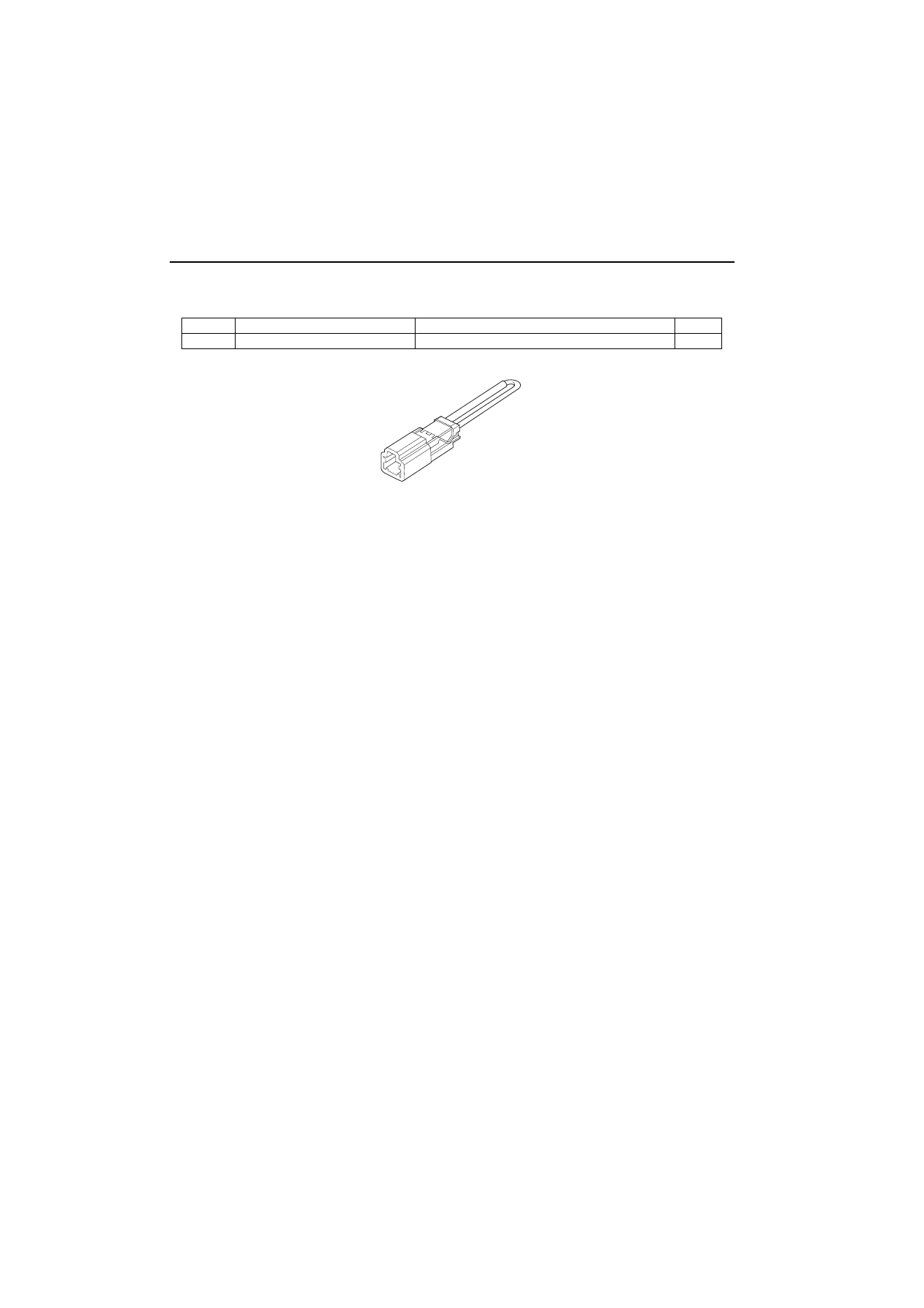
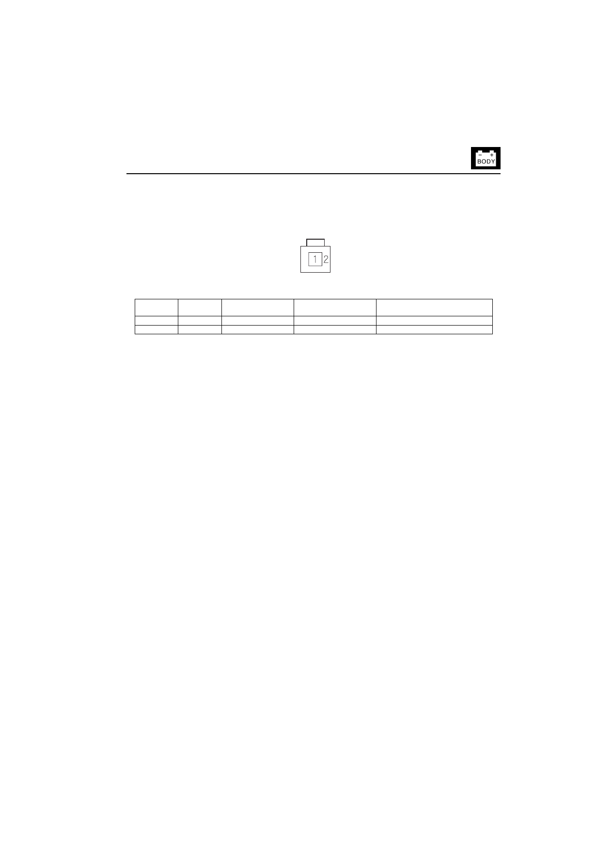
6SHFLDO7RROV
6SHFLDO7RROV
5HI1R
7RRO1XPEHU
'HVFULSWLRQ
4W\
07PAZ-0010100
SCS Short Connector
1
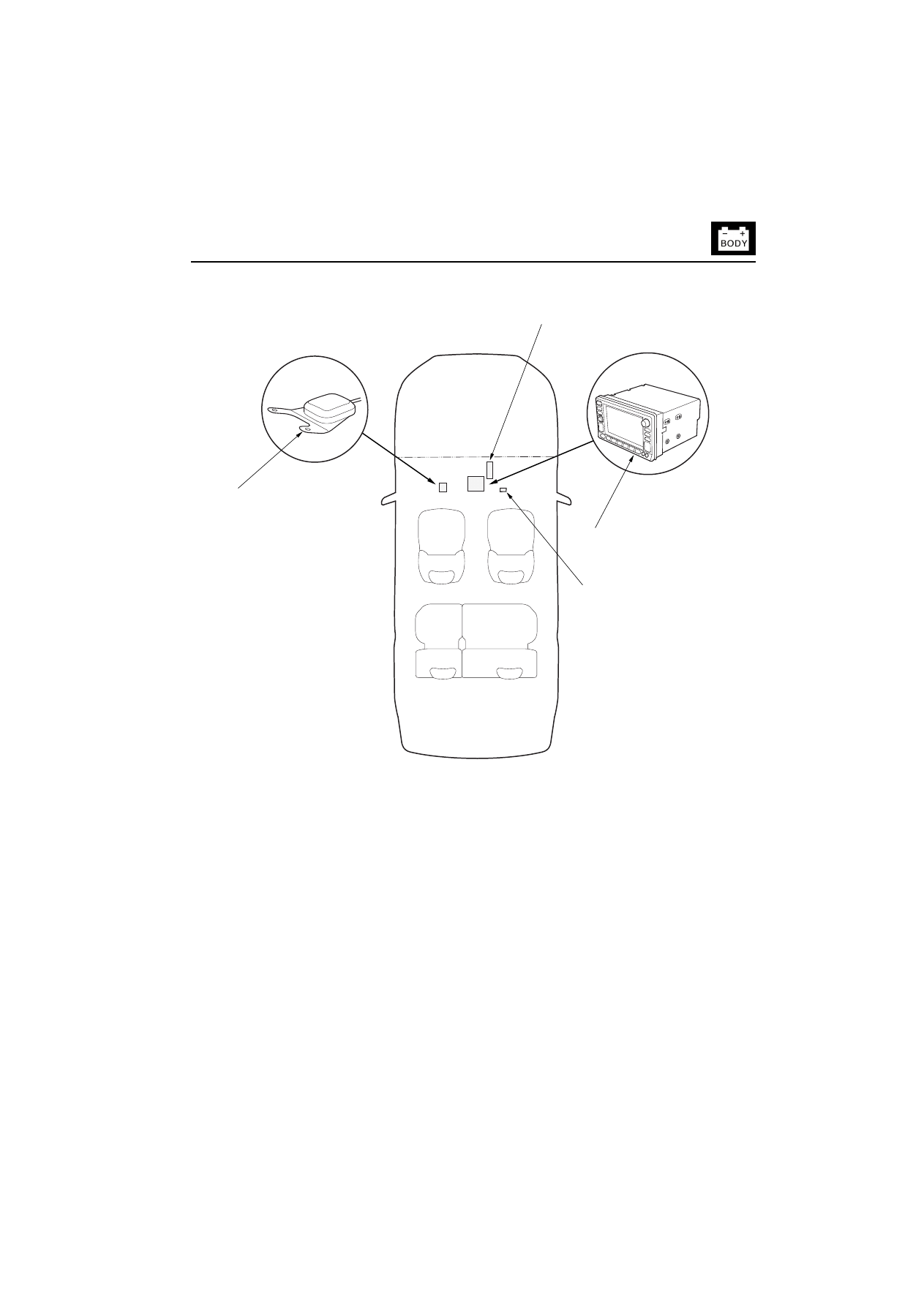
&RPSRQHQW/RFDWLRQ,QGH[
%
&RPSRQHQW/RFDWLRQ,QGH[
3&0)RU9HKLFOH6SHHG3XOVH963
$9181,7
1$9,*$7,216(59,&(&+(&.&211(&725
*36$17(11$

%
1DYLJDWLRQ6\VWHP
*HQHUDO7URXEOHVKRRWLQJ,QIRUPDWLRQ
*HQHUDO7URXEOHVKRRWLQJ,QIRUPDWLRQ
*HQHUDO2SHUDWLRQ
Refer to the Honda Navigation System Owner’s manual for
the navigation system operating procedures.
$QWLWKHIW)HDWXUH
The navigation system has a coded theft protection circuit.
Be sure to get the customer’s five-digit security code
number before;
disconnecting the battery
disconnecting navigation unit connector A (12P)
removing the No. 9 (10A) fuse from the under-hood
fuse/relay box
After service, reconnect power to the navigation unit, and
turn the ignition switch ON (II). Enter the five-digit security
code.
When replacing the navigation unit, be sure to give the
customer the new anti-theft security code.
6\PSWRP'LDJQRVLV
Certain circumstances and system limitations will result in
occasional vehicle positioning errors. Some customers
may think this indicates a problem with the navigation
system when, in fact, the system is normal. Keep the
following items in mind when interviewing customers about
navigation system symptoms.
6HOI,QHUWLDO1DYLJDWLRQ/LPLWDWLRQV
The limitations of the self-inertial portion of the navigation
system (the yaw rate sensor and the vehicle speed signal)
can cause some discripancies between the vehicle’s
actual position and the indicated vehicle position (GPS
vehicle position). However, if GPS signals cannot be
received, you must tune the vehicle position manually.
The following circumstances may cause vehicle
positioning errors:
Moving the vehicle with the engine stopped, such as by
ferry or tow truck, or if the vehicle is spun on a turn table
Tire slippage, changes in tire rolling diameters, and
some driving situations may cause discrepancies in
travel distances. Examples of this include:
– Continuous tire slippage on a slippery surface
– Driving with snow chains mounted
– Abnormal tire pressure
– Incorrect tire size
– Frequent lane changes across a wide highway
– Continuous driving on a straight or gently curving
highway
Tolerances in the system and map inaccuracies
sometimes limit how precisely the vehicle position is
indicated. Examples of this include:
– Driving on roads not shown on the map (map
matching is not possible)
– Driving on a road that winds in one derection, such
as a loop bridge, an interchange, or a spiral parking
garage
– Driving on a road with a series of sharp hair-pin
turns
– Driving on one of two close parallel roads
– After making many 90 degree turns
*OREDO3RVLWLRQLQJ6\VWHP*36
/LPLWDWLRQV
The GPS cannot detect the vehicle's position during the
following instances:
For the first 5 to 10 minutes after reconnecting the
battery
When the satellite signals are blocked by tall building,
mountains, tunnels, large trees, or large trucks
When the GPS antenna is blocked by something on the
dashboard
When there is no satellite signal output (Signal output is
sometimes stopped for satellite servicing)
When the satellite signals are blocked by the operation
of some electronic after market accessories.
The accuracy of GPS is reduced during these instances:
When only two satellite signals can be received (Three
satellite signals are required for accurate positioning)
When the satellite control centers are experiencing
problems

*HQHUDO7URXEOHVKRRWLQJ,QIRUPDWLRQ
%
/&''LVSOD\8QLW/LPLWDWLRQV
In cold temperatures, the display may stay dark for the
first 2 or 3 minutes until it warms up.
When the display is too hot because of direct summer
sunlight, it will remain dark until the temperature drops.
When the humidity is high and the interior temperature is
low, the display may appear cloudy. The display will
clear up after some use.
6\PSWRP'XSOLFDWLRQ
When the symptom can be duplicated, follow the self-
diagnostic procedures (picture diagnosis mode) and the
appropriate troubleshooting procedures.
When the symptom does not reappear or only
reappears intermittently, ask the customer about the
conditions when the symptom occured.
– Try to establish if outside interference may have
been the cause.
– Try to duplicate the symptom under the same
conditions the customer was experiencing.
– Vibration, temperature extremes, and moisture
(dew, humidity) are factors that are difficult to
duplicate.
6HUYLFH3UHFDXWLRQV
Before disconnecting the battery, make sure you have
the anti-theft codes for the radio and the navigation
system, and write down the frequencies for the radio's
preset buttons.
After servicing, park the vehicle in an area where the
GPS satellite signals will be unobstructed, and check
the satellite mark on the display.
When the battery is disconnected, the clock is reset to
''0:00''. The clock will reset to the correct time after the
system receives the GPS satellite signals.
After reconnecting the battery, you have to wait to get
the initial signal from the satellite. It will take about ten
minutes.

%
1DYLJDWLRQ6\VWHP
6\PSWRP7URXEOHVKRRWLQJ,QGH[
6\PSWRP7URXEOHVKRRWLQJ,QGH[
6\PSWRP
'LDJQRVWLFSURFHGXUH
$OVRFKHFNIRU
No picture is shown on the display
Troubleshooting
The picture is missing a color or tone
Troubleshooting
AVN unit buttons do not work
Replace the AVN unit.
Satellite mark in the GPS mark is not
indicated
Troubleshooting
Electronic after market
accessories
Audio driving instructions cannot be heard
Troubleshooting
Vehicle position does
not move on the map
Vehicle position does not move on the map
Troubleshooting
6\VWHP'HVFULSWLRQ
%
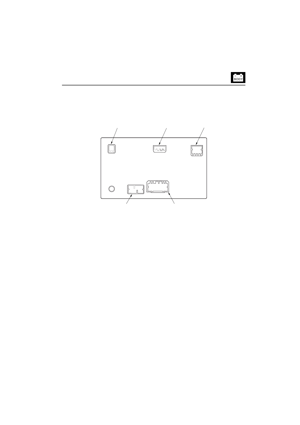
6\VWHP'HVFULSWLRQ
&RQQHFWRU/RFDWLRQV
$91XQLW
(cont’d)
*36$17(11$3
&211(&725
&211(&725'3
1RWXVHG
&211(&725$3
)RUQDYLJDWLRQV\VWHP
&211(&725%3
)RUDXGLRV\VWHP
&211(&725&3
1RWXVHG
%
1DYLJDWLRQ6\VWHP
6\VWHP'HVFULSWLRQ
6\VWHP'HVFULSWLRQFRQW¶G
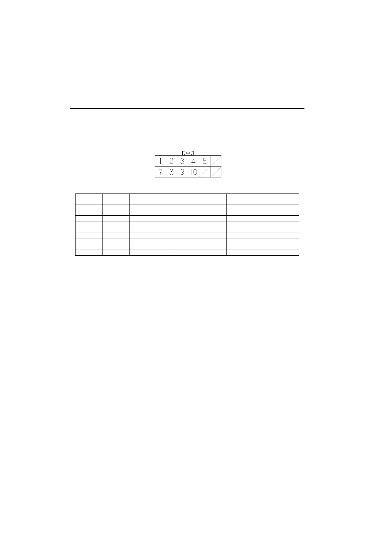
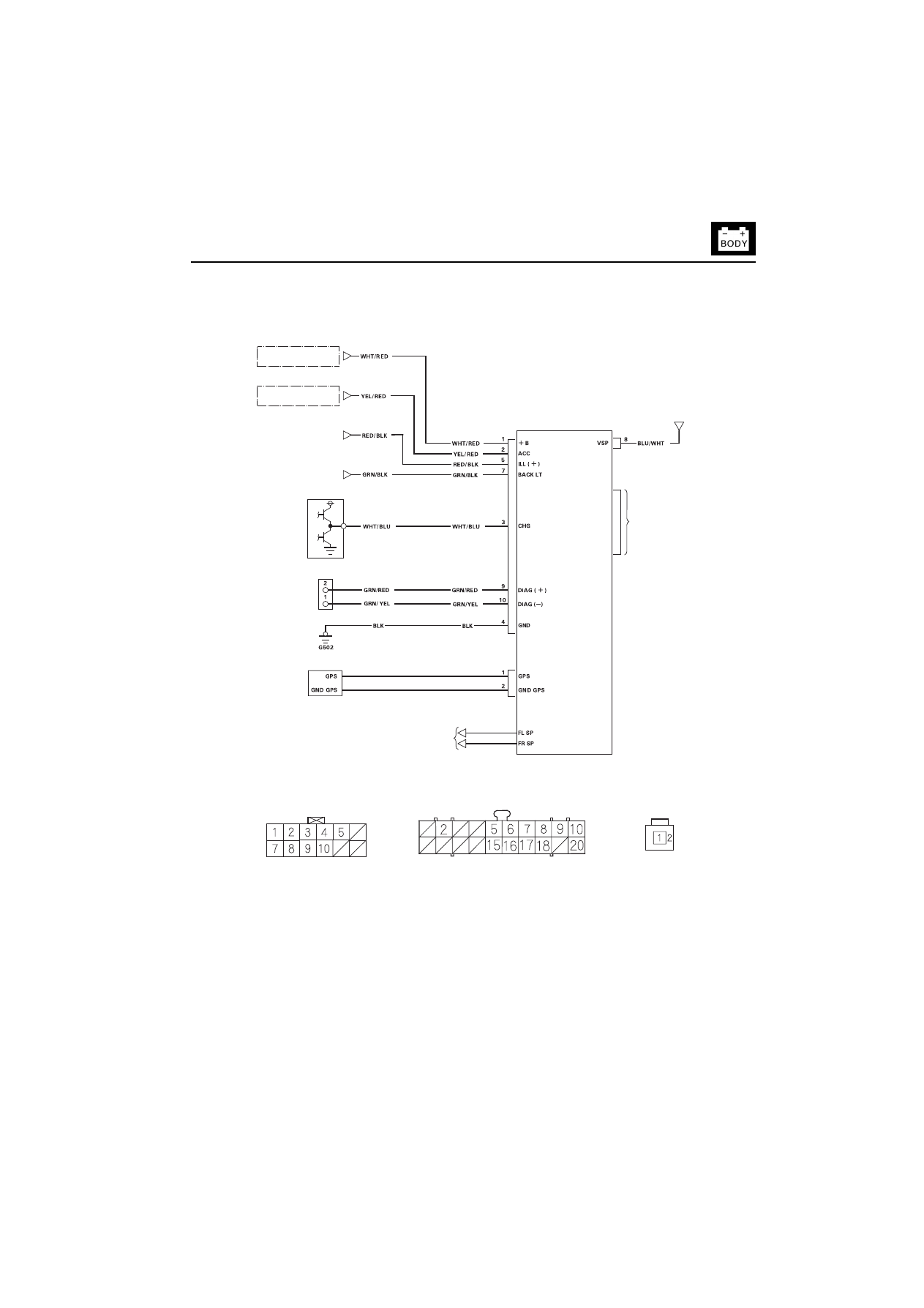
$918QLW,QSXWVDQG2XWSXWVIRU&RQQHFWRU$3
$9181,7&211(&725$3
Wire side of female terminals
7HUPLQDO
QXPEHU
:LUHFRORU
7HUPLQDO
7HUPLQDOQDPH
'HVFULSWLRQ
1
WHT/RED
+B
+B power source
Continuous power source
2
YEL/RED
ACC
Accessory
Power source for accessory
3
WHT/BLU
CHG
Charge
Engine ON signal
4
BLK
GND
Ground
Ground for AVN unit
5
RED/BLK
ILL (+)
Illumination positive
Power source for illumination
7
GRN/BLK
BACK LT
Back light
Reverse signal of select lever
8
BLU/WHT
VSP
Vehicle speed pulse
Vehicle speed pulse signal
9
GRN/RED
DIAG (+)
Diagnosis positive
Signal for forced starting of display
10
GRN/YEL
DIAG (-)
Diagnosis negative
Signal for forced starting of display
6\VWHP'HVFULSWLRQ
%
$91,QSXWVDQG2XWSXWVIRU*36DQWHQQD3&RQQHFWRU
*36$17(11$3&211(&725
Wire side of female terminals
(cont’d)
7HUPLQDO
QXPEHU
:LUHFRORU
7HUPLQDO
7HUPLQDOQDPH
'HVFULSWLRQ
1
——
GPS
GPS
GPS signal
2
——
GPS GND
GPS ground
Ground for GPS antenna
%
1DYLJDWLRQ6\VWHP
6\VWHP'HVFULSWLRQ
6\VWHP'HVFULSWLRQFRQW¶G
2YHUYLHZ
The Honda Navigation System is a highly-sophisticated, hybrid locating system that uses satellites and a map database to
show you where you are and to help guide you to a desired destination.
The Navigation System receives signals from the Global Positioning System (GPS), a network of 24 satellites in orbit around
the earth. By receiving signals from serveral of these satellites, the Navigation System can determine the latitude and
longitude of the vehicle. In addition, signals from the system’s yaw rate sensor and the vehicle speed pulse (VSP) sensor
enable the system to keep track of the vehicle’s direction and speed of travel.
This hybrid system has advantages over a system that is either entirely self-contained or one that relies totally on the GPS.
For example, the self-contained portion of the system can keep track of vehicle position even when satellite signals cannot
be received, and the GPS can keep track of the vehicle position even when the vehicle is transported by ferry.
The Navigation System applies all this location, direction, and speed information to the maps and calculates a route to the
destination entered. As you drive to that destination, the system provides both visual and audio guidance.
6\VWHP'LDJUDP
$0)05$',2$17(11$
63($.(5
$8',281,7
',63/$<81,7
$9181,7
3&09(+,&/(
63(('38/6(
963
*36$17(11$
*36
5(&(,9(5
<$:5$7(
6(1625
'9''5,9(
&''5,9(
6\VWHP'HVFULSWLRQ
%
1DYLJDWLRQ)XQFWLRQ
The navigation system is composed of the AVN unit, the PCM vehicle speed pulse (VSP) signal, the GPS antenna.
)XQFWLRQ'LDJUDP
9HKLFOH6SHHG3XOVH963
The vehicle speed pulse (VSP) is outputted by the PCM. The PCM recieves the signal from the countershaft speed sensor,
then the PCM prosesses the signal and transmits it to the speedometer and other systems.
<DZ5DWH6HQVRU
The yaw rate sensor detects the direction change (angular speed) of the vehicle. The sensor is oscillation gyro built into the
AVN unit.
(cont’d)
5HFHSWLRQRIUDGLRZDYH
IURPVDWHOOLWH
'HWHFWLRQRIWUDYHO
GLVWDQFH
'HWHFWLRQRIYHKLFOH
SRVLWLRQ
*36WXQLQJ
3HUFHSWLRQRIYHKLFOH
SRVLWLRQ
&RUUHFWLRQRIPDS
PDWFKLQJ
'HWHFWLRQRIGLUHFWLRQ
FKDQJH
0DSVFUROO
&KDQJHRIUHGXFHGVFDOH
RIPDS
'DWDSURFHVVFRQFHUQLQJ
PDSDQGYHKLFOHSRVLWLRQ
/&'
6:,7&+
'HVWLQDWLRQ
'9'520
$9181,7
<$:5$7(6(1625
*365(&(,9(5
9(+,&/(63(('38/6(
9636(1625
*36$17(11$
9(+,&/(63(('38/6(9636(1625
$9181,7
6HQVRUSRZHU
',67$1&(
'(7(&7,21
&,5&8,7
%
1DYLJDWLRQ6\VWHP
6\VWHP'HVFULSWLRQ
6\VWHP'HVFULSWLRQFRQW¶G
*OREDO3RVLWLRQLQJ6\VWHP*36
The Global Positioning System (GPS) enables the navigation system to determine the current position of the vehicle by
using the electronic waves transmitted from the satellites in orbit around the earth. The satellites transmit the satellite
identification signal, orbit information, transmission time signal, and other information. When the GPS receiver receives the
electronic waves from three or more satellites simultaneously, it calculates the current position of the vehicle based on the
distance to each satellite and the satellite positions on their respective orbits.
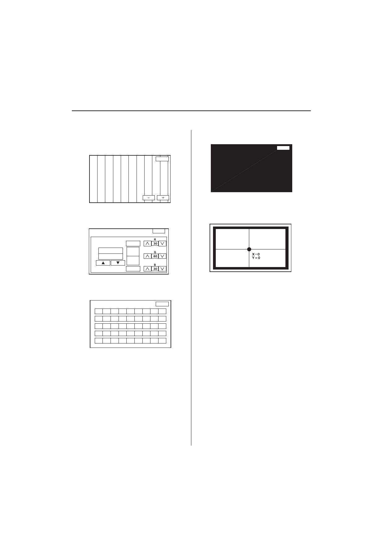
3RVLWLRQGHWHFWLRQ,PDJHZLWK*36VDWHOOLWH
3UHFLVLRQRI*36
The precision of the GPS varies according to the number of satellites from which electronic waves are received and the
control condition. The precision is indicated by the GPS mark shown on the upper left of the display.
*36$QWHQQD
Receiving the electronic waves from the satellites, the GPS antenna amplifies and transmits them to the GPS receiver.
*365HFHLYHU
The GPS receiver is built in to AVN unit. It calculates the vehicle position by receiving the signal from the GPS antenna. The
vehicle position and signal reception condition is transmitted from the GPS receiver to the AVN unit to adjust the vehicle
position.
*360$5.
1RRI
6$7(//,7(6
&21',7,21
'(6&5,37,21
No satellite
mark
→
Two or less
Impossible to detect
vehicle position
The GPS function is normal.
The satellite electronic waves that
are received by the GPS receiver
are to few to determine the vehicle
position.
Yellow satellite
mark
→
Three
Vehicle position
detectable in two
dimensions
The longitude and latitude of the
vehicle position can be determined.
(Less precise than detection in
three dimensions)
Green satellite
mark
→
Four or more
Vehicle position
detectable in three
dimensions
The longitude, latitude and the
altitude of the vehicle position can
be determined. (More precise than
detection in two dimensions)
Not indicate
——
Faulty
The GPS can't be used due to a
faulty GPS receiver, open in the
antenna wire, or other fault.
NOTE: Four satellites on each of six orbits

6\VWHP'HVFULSWLRQ
%
$918QLW
The AVN unit calculates the vehicle position and guides you to the destination. The unit performs map matching correction,
GPS correction, and distance tuning. It also controls the menu functions and the DVD-ROM drive. With control of all these
items, the AVN unit makes the navigation picture signal, then it transmits the signal to the display unit and audio driving
instructions to the audio unit.
&DOFXODWLRQRI9HKLFOH3RVLWLRQ
The AVN unit calculates the vehicle position (the driving direction and the current position) by receiving the directional
change signals from the yaw rate sensor and the travel distance signals from the vehicle speed pulse (VSP) sensor.
0DS0DWFKLQJ7XQLQJ
The map matching tuning is accomplished by indicating the vehicle position on the roads on the map. The map data
transmitted from the DVD-ROM is checked against the vehicle position data, and the vehicle position is indicated on the
nearest road. Map matching tuning does not occur when the vehicle travels on a road not shown on the map, or when the
vehicle position is far away from a road on the map.
*367XQLQJ
The GPS tuning is accomplished by indicating the vehicle position as the GPS’s vehicle position. The AVN unit compares its
calculated vehicle position data with the GPS vehicle position data. If there is large difference between the two, the indicated
vehicle position is adjusted to the GPS vehicle position.
'LVWDQFH7XQLQJ
The distance tuning reduces the difference between the travel distance signal from the VSP and the distance data on the
map. The AVN unit compares its calculated vehicle position data with the GPS vehicle position data. The AVN unit then
decreases the tuning value when the vehicle position is always ahead of the GPS vehicle position, and it increases the
tuning value when the vehicle position is always behind the GPS vehicle position.
5RXWH*XLGDQFH
The AVN unit can calculate different routes to a selected destination. You have four options:
Direct Route - Calculate a route that is the most direct and will take the least time.
Easy Route - Calcute a route that minimizes the number of turns needed.
Minimize Motorways - Calculate a route that avoids motorway travel. If that is not possible, keep the amount of motorway
travel to a minimum.
Minimize Toll Roads - Calculate a route that avoids, or minimizes travel on toll roads.
$XGLR*XLGDQFH
The AVN unit transmits audio driving instructions before entering an intersection or passing a junction.
The audio instructions come through audio unit and the front speakers.
'9'520
The map data (including all scale rates) is stored in the DVD-ROM. The map data includes:
Road distances, road widths, speed limits, traffic regulations, passing time at junction, distances to junctions, and the
driving instructions for audio guidance.
Latitude and longitude GPS.
(cont’d)
%
1DYLJDWLRQ6\VWHP
6\VWHP'HVFULSWLRQ
6\VWHP'HVFULSWLRQFRQW¶G
$XGLR8QLW
The audio unit built in the AVN unit. It receives the audio driving instructions from the navigation unit and transmits the
instructions through the front speakers even when the audio system is in use.
'LVSOD\8QLW
The display unit built in the AVN unit. It uses Liquid Crystal Display (LCD). The LCD is a 6-inch-wide, Thin Film Transistor
(TFT), stripe type with about 280,000 picture elements. The color film and fluorecent light are laid out on the back of the liquid
crystal film.
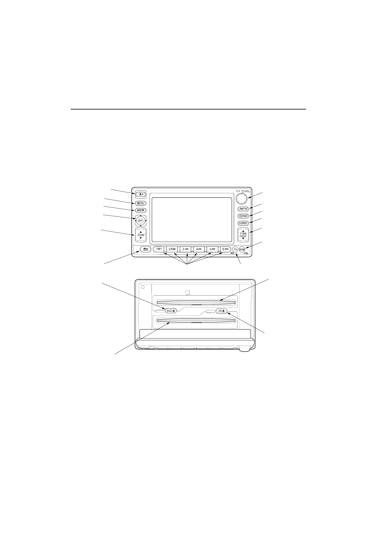
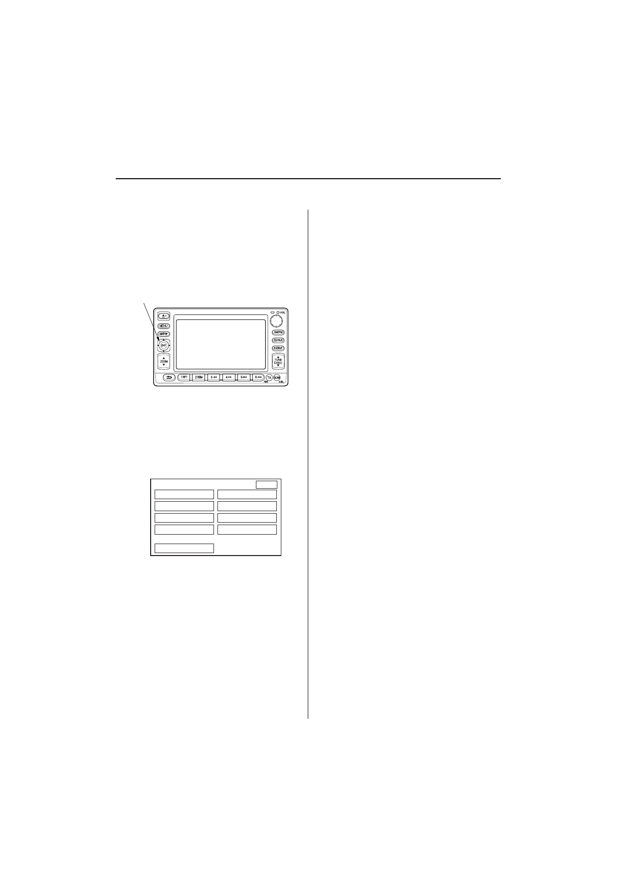
2SHUDWLRQNH\V
23(1%87721
0(18%87721
0$3%87721
-2<67,&.(17
=220%87721
&$1&(/%87721
35(6(7%877216
7$%877216
92/80(.12%
$0)0%87721
$&$8;%87721
$8',2%87721
781(',6&%87721
6&$1%87721
'9'6/27
&'(-(&7
%87721
'9'(-(&7%87721
&'6/27
&LUFXLW'LDJUDP
%
&LUFXLW'LDJUDP
81'(5+22')86(5(/$<%2;
81'(5'$6+)86(5(/$<%2;
1R$)86(
1R$)86(
60$///,*+75(/$<
5(9(56(5(/$<
&211(&725$
3
$9181,7
&211(&725
$3
3&09(+,&/(
63(('38/6(
&211(&725%
3
)RUDXGLRV\VWHP
1$9,*$7,216(59,&(
&+(&.&211(&725
*36$17(11$
*36$17(11$3
&211(&725
7RIURQWVSHDNHUV
$9181,7&211(&7256
&211(&725$3
&211(&725%3
*36$17(11$3&211(&725
:LUHVLGHRIIHPDOHWHUPLQDOV
$/7(51$725
%
1DYLJDWLRQ6\VWHP
6\PSWRP7URXEOHVKRRWLQJ
6\PSWRP7URXEOHVKRRWLQJ
1RSLFWXUHLVVKRZQRQWKHGLVSOD\
Check the No. 9 (10A) fuse in the under-hood fuse/
relay box.
,VWKHIXVH2."
<HV
Reinstall the fuse, and go to step 2.
1R
Replace the fuse, and recheck.
■
Check the No. 8 (7.5A) fuse in the under-dash fuse/
relay box.
,VWKHIXVH2."
<HV
Reinstall the fuse, and go to step 3.
1R
Replace the fuse, and recheck.
■
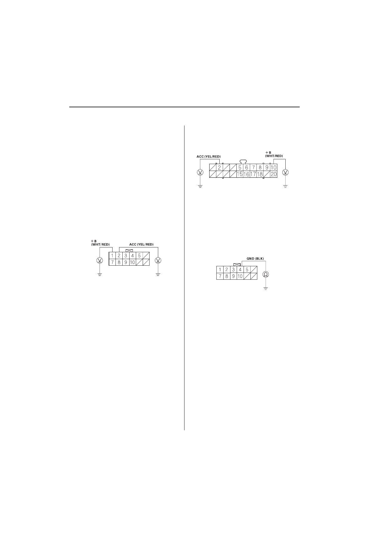
Turn the ignition switch ON (II).
Measure the voltage between body ground and
AVN unit connector A (12P) terminals No. 1 and
No. 2 individually.
$9181,7&211(&725$3
Wire side of female terminals
,VWKHUHEDWWHU\YROWDJH"
<HV
Go to step 5.
1R
Repair open in the wire between the fuse/
relay box and the AVN unit.
■
Measure the voltage between body ground and
AVN unit connector B (20P) terminals No. 2 and
No. 10.
$9181,7&211(&725%3
Wire side of female terminals
,VWKHUHEDWWHU\YROWDJH"
<HV
Go to step 6.
1R
Repair open in the wire between the fuse/
relay box and the AVN unit.
■
Turn the ignition switch OFF.
Check for continuity between AVN unit connector A
(12P) terminal No. 4 and body ground.
$9181,7&211(&725$3
Wire side of female terminals
,VWKHUHFRQWLQXLW\"
<HV
Go to step 8.
1R
Repair open in the wire between the AVN unit
and body ground (G502).
■
6\PSWRP7URXEOHVKRRWLQJ
%
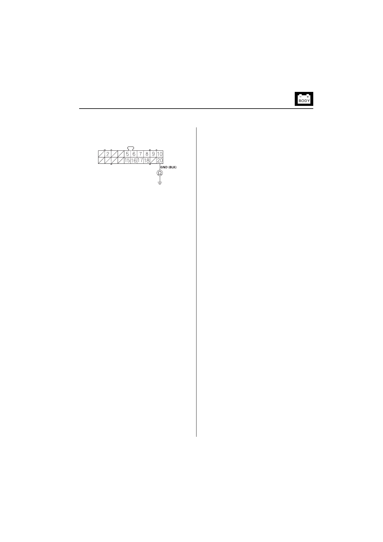
Check for continuity between AVN unit connector B
(20P) terminal No. 20 and body ground.
$9181,7&211(&725%3
WIre side of female terminals
,VWKHUHFRQWLQXLW\"
<HV
Go to step 9.
1R
Repair open in the wire between the AVN unit
and body ground (G502).
■
Perform the forced starting of display
.
,VWKHGLDJQRVLVPHQXRIWKHSLFWXUHGLDJQRVLV
GLVSOD\HG"
<HV
Perform the System Links Test in the Picture
Diagnosis Test menu
■
1R
Replace the AVN unit.
■
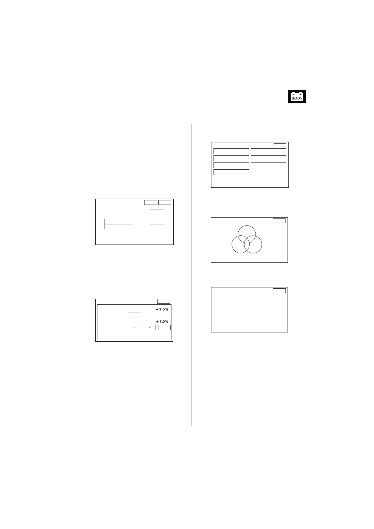
7KHSLFWXUHLVPLVVLQJD5HG*UHHQRU%OXH
FRORURUWRQH
Perform the start-up procedure
.
Select the Monitor Check then select the RGB
Color
$UHWKH5HG*UHHQDQG%OXHFRORUHGFLUFOHVVKRZQ"
<HV
Select the Return. Select the Color Change,
and then Select the Default to restore the
standard color settings.
■
1R
Replace the AVN unit.
■

%
1DYLJDWLRQ6\VWHP
6\PSWRP7URXEOHVKRRWLQJ
6\PSWRP7URXEOHVKRRWLQJFRQW¶G
6DWHOOLWHPDUNLQWKH*36PDUNLVQRW
LQGLFDWHG
Perform the System Link check under the picture
diagnosis
,V1*LQGLFDWHG"
<HV
Repair as indicated by the system link
check.
■
1R
Check that nothing is blocking the GPS
antenna located under the dash board, and
recheck where nothing can block the GPS
satellite signal.
■
$XGLRGULYLQJLQVWUXFWLRQVFDQQRWEHKHDUG
Check the audio driving instructions volume setting.
,VLWVHWWR2))"
<HV
Set the volume to an audible level.
■
1R
Go to step 2.
Perform the System Link check under the picture
diagnosis
&DQWKHVRXQGEHKHDUG"
<HV
The system is OK at this time.
■
1R
Go to step 3.
Check for open and short to body ground in the
speaker circuits.
$UHWKHFLUFXLWV2."
<HV
Go to step 4.
1R
Repair open or short to body ground in the
wire speaker circuits.
■
Check the speaker.
,VWKHVSHDNHU2."
<HV
Replace the AVN unit.
■
1R
Replace the speaker.
■

6\PSWRP7URXEOHVKRRWLQJ
%
9HKLFOHSRVLWLRQGRHVQRWPRYHRQWKHPDS
Start the engine.
Perform the Car Status Test under the Picture
Diagnosis Test menu
,VWKHUHYHKLFOHVSHHGSXOVHVLJQDO"
<HV
Replace the AVN unit.
■
1R
Check the VSP circuit. If the circuit is OK,
replace the AVN unit.
■
%
1DYLJDWLRQ6\VWHP
3LFWXUH'LDJQRVLV7HVW
3LFWXUH'LDJQRVLV7HVW
6WDUWXSSURFHGXUH
Turn the ignition switch ON (II), then press and hold
the keys in this order: (1) Key 1, (2) Key 2, (3) Key
6, and keep them pressed simultaneously for 5
seconds.
2SHUDWLRQNH\V
Joystick: Use for select the item
After the display changes to the diagnosis menu
screen, select the item you want to check, and the
check will start. To return to previous screen, select
’’Return’’ on the diagnosis screen.
When you quit picture diagnosis test, return to
standard nevigation screen and then turn the ignition
switch OFF. If you turn the ignition switch OFF when
the diagnosis screen displayed, the system will not
work.
'LDJQRVLVLWHPV
System Links
Tire Calibrate
Monitor Check
Yaw Rate
Unit Check
Cyclic Diag
Vehicle Position
Start demo mode
In-line Diag
&\FOLF'LDJ
This test is for manufacturer’s use only. In this test, the
system checks the following items repeatedly:
AVN unit check
Monitor check
To exit this test, press the cancel key.
9HKLFOH3RVLWLRQ
When moving the vehicle with the engine stopped such as
ferry or tow truck and vehicle positioning error occured,
you can adjust the vehicle position using the joystick.
6WDUWGHPRPRGH
This test is for manufacturer’s use only. If the indication of
this item is changed to ’’Stop demo mode’’, select this item
once and make sure the indication changes to ’’Start demo
mode’’.
,QOLQH'LDJ
This test is for manufacturer’s use only. In this test, the
system checks the following items:
System Links
Car status
Yaw Rate
-2<67,&.
5HWXUQ
'LDJQRVLV0HQX
6\VWHP/LQNV
0RQLWRU&KHFN
8QLW&KHFN
9HKLFOH3RVLWLRQ
7LUH&DOLEUDWH
<DZ5DWH
&\FOLF'LDJ
6WDUWGHPRPRGH
,QOLQH'LDJ
3LFWXUH'LDJQRVLV7HVW
%
6\VWHP/LQNV
If the system is OK, all of the communication lines
connecting the components color will not change, the
screen will indicate ’’OK’’, and a tone will sound.
If there is a problem in the system, the faulty
components will change to red, the screen will indicate
’’NG’’, and tone will sound.
If the ’’GPS’’ is in red and the screen indicates ’’NG’’,
check the GPS communication line. If the line is OK,
replace the GPS antenna.
If the component exept ’’GPS’’ is in red and the screen
indicates ’’NG’’, replace the AVN unit.
7LUH&DOLEUDWH
The ’’Auto-Tuning’’ is factory-set to ’’ON’’, and it should
remain ON. If you find it has been turned OFF, turn it
back ON.
The ’’Tire-Cal Tuning’’ can be used, but it is not
recommended. The ’’AUTO TUNING’’ fanction keeps the
system in better tune.
0RQLWRU&KHFN
Select the item you want to check, and the check starts.
5*%&RORU
The three primary colors of red, green and blue must be
shown.
:KLWH5DVWHU
The entire display must be in white.
(cont’d)
2.
5HWXUQ
$17
'LVS
$XGLR
1DYL(&8
*36
6\VWHP/LQNV
7LUH&DOLEUDWH
7LUH&DO)DFWRU
$XWR7XQLQJ
7LUH&DO7XQLQJ
21
67'
6HW
5HWXUQ
5HWXUQ
0RQLWRU&KHFN
5*%&RORU
:KLWH5DVWHU
*UD\7RQHV
&RORU&KDQJH
7HVW3DWWHUQ
%ODFN5DVWHU
6FUHHQ$GMXVWPHQW
5HWXUQ
5HG
*UHHQ
%OXH
5HWXUQ
%
1DYLJDWLRQ6\VWHP
3LFWXUH'LDJQRVLV7HVW
3LFWXUH'LDJQRVLV7HVWFRQW¶G
*UD\7RQHV
The gray tone level must be changed smoothly in
holyzontal direction. If you want to change the contrast of
the screen, select ’’+’’ or ’’-’’.
&RORU&KDQJH
This screen is for manufacturer’s only.
7HVW3DWWHUQ
The system color palette must be indicated.
%ODFN5DVWHU
The entire display must be shown in black.
6FUHHQ$GMXVWPHQW
In this screen, you can adjust the screen position in the
display. Use the joystick to adjust the screen position.
5HWXUQ
5HWXUQ
&RORU&KDQJH
&RORU1R
%22.
'HIDXOW
6HW
5HWXUQ
5HWXUQ
6FUHHQ$GMXVWPHQW
3LFWXUH'LDJQRVLV7HVW
%
8QLW&KHFN
Select the item you want to check, and the check starts.
NOTE: Do not use ’’Backup Clear’’ and ’’Force Download’’.
These commands are for the manufacturer’s use only.
'LVS
When any item is ’’NG’’, replace the AVN unit.
*36
This screen shows the condition of the GPS reception and
the vehicle position.
1DYL(&8
When any item is ’’NG’’, replace the AVN unit.
6\VWHP+LVWRU\
This screen is for manufacturer’s use only.
(cont’d)
5HWXUQ
8QLW&KHFN
'LVS
*36
1DYL(&8
6\VWHP+LVWRU\
&DU6WDWXV
%DFNXS&OHDU
)RUFH'RZQORDG
5HWXUQ
2.
2.
'LVS
&RQQHFWLRQ
2.
520
2.
5$0
5HWXUQ
*36,QIRUPDWLRQ
1XPEHURI
6DWHOOLWHV
&XUUHQW3RVLWLRQ
/DWLWXGH;;;;·;;µ
/RQJLWXGH;;;;·;;µ
(OHYDWLRQ;;;IW
,QXVH
6HDUFK
5HWXUQ
2.
+LJK7PS
/RZ7PS
)ODVK,3/
)ODVK$SSOLFDWLRQ
5$0
95$02YHUOD\
95$0%DVH
0RGHO
1DYL(&8
5HWXUQ
6\VWHP+LVWRU\
/(9(/
/(9(/
/(9(/
%
1DYLJDWLRQ6\VWHP
3LFWXUH'LDJQRVLV7HVW
3LFWXUH'LDJQRVLV7HVWFRQW¶G
&DU6WDWXV
Use the car status screen to check each signal.
If the indication does not match the actual vehicle status,
check the applicable signal line.
’’VSP’’ (vehicle speed pulse indication)
– ''OFF'' when vehicle is not moving
– ''ON'' when vehicle is moving
''BACK'' (reverse indication)
– ''OFF'' when shift lever is in any position other than
reverse
– ''ON'' when shift lever is in reverse
''ILL'' (illumination indication)
– ''OFF'' when parking lights or headlights are off
– ''ON'' when parking lights or headlights are on
''CHG'' (charging indication)
– ''ON'' when engine is running and alternator is
charging
– ''OFF'' when engine is off or alternator is not
charging
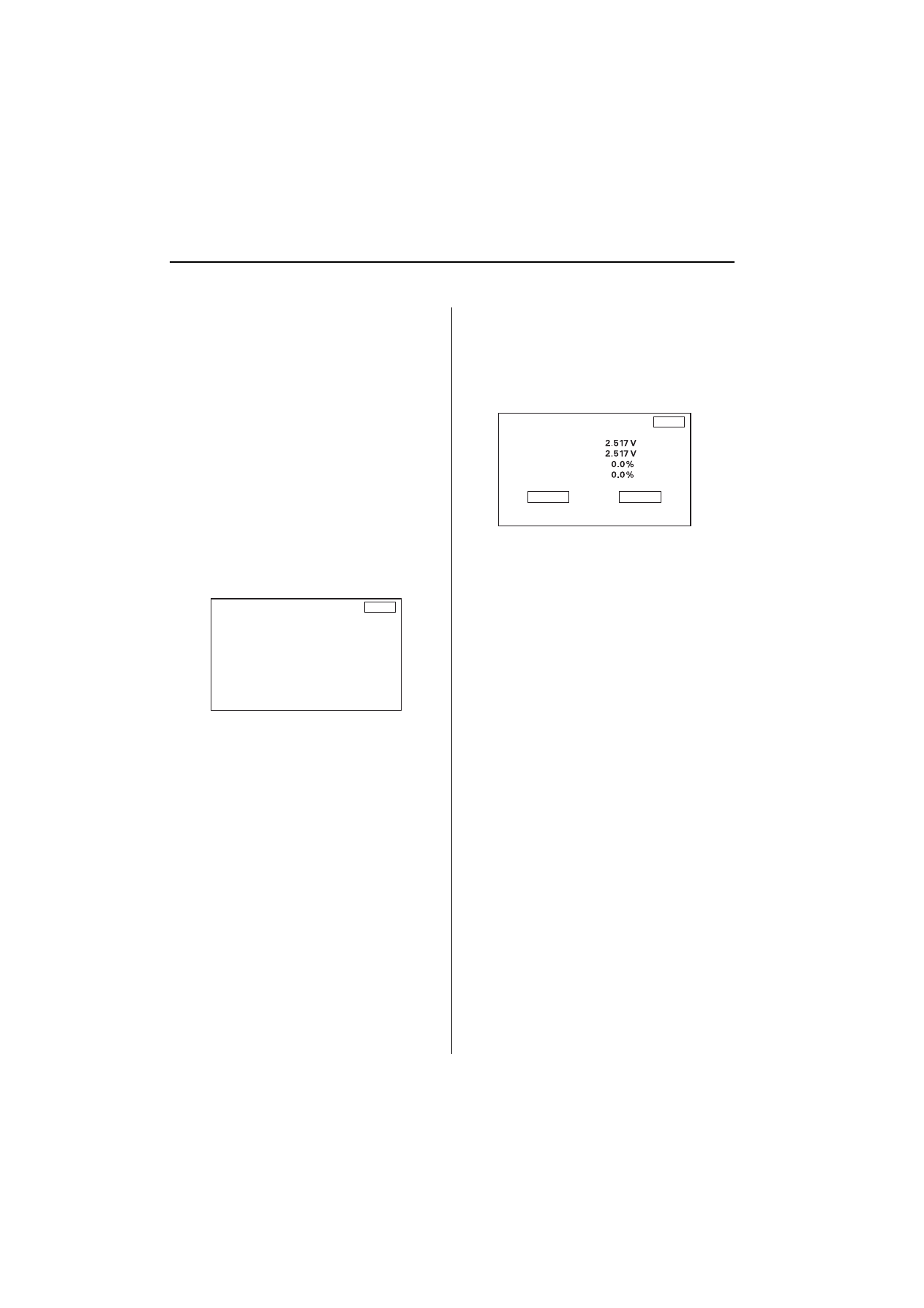
<DZ5DWH
''SENSOR'' indicator the voltage output from the yaw rate
sensor. It should indicate 1,500 to 3,500 V with the vehicle
stopped.
NOTE: Do not try to tune the yaw rate sensor unless
instructed by Honda Motor Europe.
5HWXUQ
&DU6WDWXV
963
2))
%$&.
2))
,//
2))
&+*
21
5HWXUQ
<DZ5DWH
2IIVHW
6HQVRU
&&:&DO)DFWRU
&:&DO)DFWRU
0RQLWRU
7XQLQJ
)RUFHG6WDUWLQJRI'LVSOD\
%
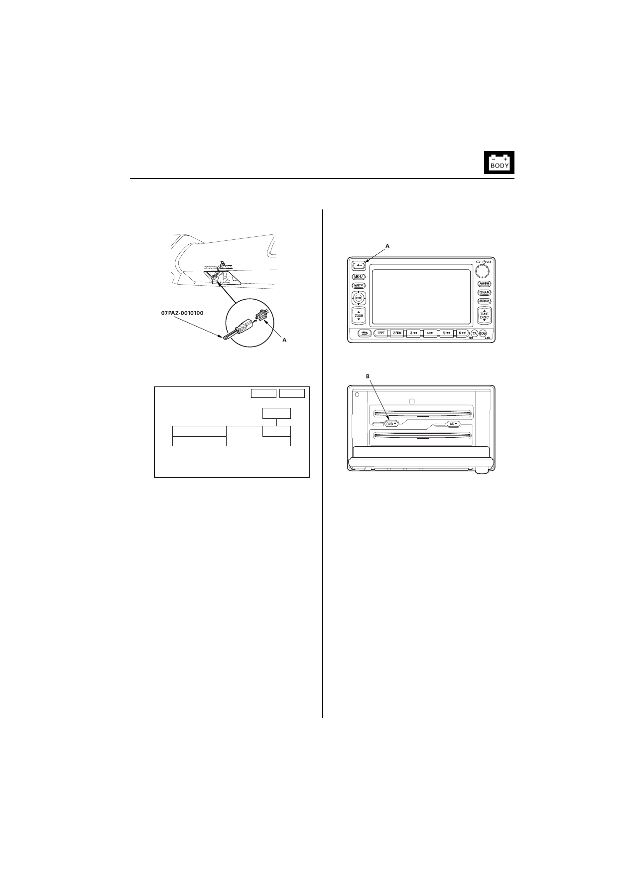
)RUFHG6WDUWLQJRI'LVSOD\
Locate the navigation service check connector (A)
upper of the data link connector.
Connect the SCS short connector to the navigation
service check connector (A).
Turn the ignition switch ON (II).
Check that the diagnosis menu for the picture
diagnosis start up and then changes to the system
link screen.
'9'5205HSODFHPHQW
Turn the ignition switch ON (II).
Push the open key (A) of the AVN unit, then open
the front panel.
Push the DVD EJECT switch (B), then remove the
DVD-ROM.
Insert the new DVD-ROM.
Close the front panel.
5HWXUQ
1*
$17
*36
'LVS
$XGLR
1DYL(&8
6\VWHP/LQNV
%
1DYLJDWLRQ6\VWHP
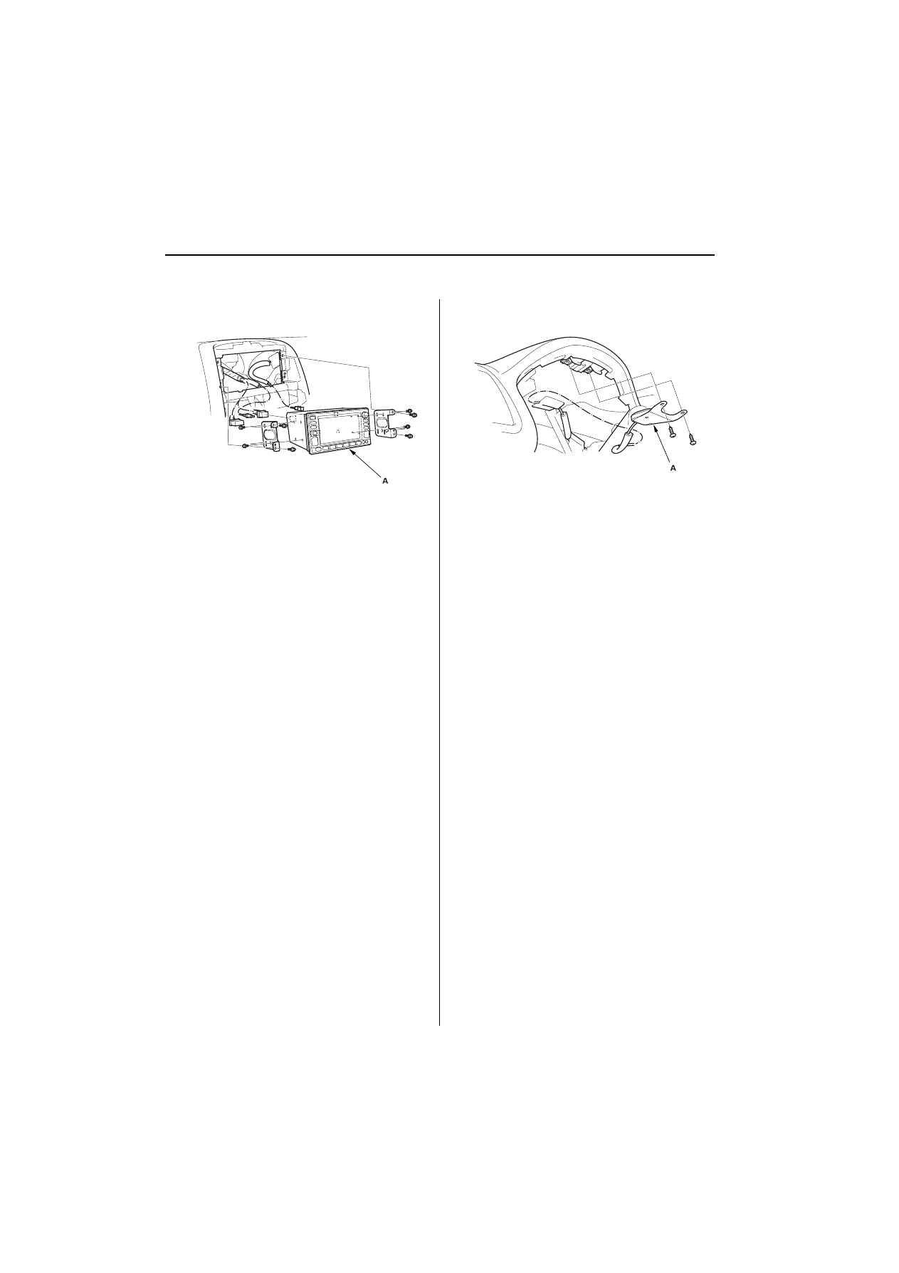
$918QLW5HPRYDO,QVWDOODWLRQ
$918QLW5HPRYDO,QVWDOODWLRQ
Remove the center panel
Remove the AVN unit (A).
Install the parts in the reverse order of removal.
*36$QWHQQD5HPRYDO,QVWDOODWLRQ
Remove the gauge assembly
Remove the GPS antenna (A).
Install the parts in the reverse order of removal.

&ORFN'LVSOD\6L]HDQG/RFDWLRQ$GMXVWPHQW
%
&ORFN'LVSOD\6L]HDQG/RFDWLRQ$GMXVWPHQW
Turn the ignition switch ON (II).
When the disclaimer is shown on the navigation display unit, select ’’OK.’’
When the ’’Enter destination by:’’ screen is shown, select ’’Setup.’’
When the ’’Setup Screen’’ is shown, select Display ’’Off.’’
Select the numbers of the clock to change the clock size and location.
If the clock is small and in the lower right hand corner of the screen, it will increase in size and move to the center of
the screen.
If the clock is large and in the center of the screen, it will decrease in size and move to the lower right hand corner of
the screen.
Push the MENU button to return to the ’’Enter destination by:’’ screen. The clock display settings will be saved.

Wyszukiwarka
Podobne podstrony:
BMW Navigation System FAQ
Audi A4 Radio navigation system (RNS D) 2002
Audi A4 Navigation system (NS LOW) 2001
10 E65 Navigation System
0775 TPI 2023632 15 Radio Navigation System RNS850 No VIN
Radio navigation system MFD CD changer and TV tuner wiring
04b E65 Navigation System
Navigation and Audio System
Group 4 Fuel System
Lumiste Tarski's system of Geometry and Betweenness Geometry with the Group of Movements
Group 025 Emission Control Systems
System finansowy w Polsce 2
Systemy operacyjne
Systemy Baz Danych (cz 1 2)
Współczesne systemy polityczne X
więcej podobnych podstron