
W H I T E P A P E R O N C H E M I C A L E N G I N E E R I N G
Fuel Cells in the
Automotive Industry
©
COPYRIGHT 1994 - 2001
by
COMSOL AB
. All rights reserved.
by
Ed Fontes
EvaNilsson

C H E M I C A L E N G I N E E R I N G I N T H E A U T O M O T I V E I N D U S T R Y
3
Fuel Cells in the
Automotive Industry
The design of catalyst reactors has made the car engine substantially cleaner during the
last two decades. Car manufacturers have applied large efforts in reducing the emissions
of hazardous gases from the combustion engine. However, it has still proven to be
difficult to eliminate NOx and SOx emissions from this process.
The chemical energy of gasoline is converted to mechanical energy via the production
of heat in the combustion process of conventional car engines. The efficiency of this
process is limited by the efficiency formula for the Carnot cycle. A more efficient
process, and one of the main candidates for power production in future cars, is the new
generation of fuel cells. These work principally as batteries do, yet while batteries can be
considered as batch reactors, fuel cells are continuous reactors. In a fuel cell-powered
engine, the chemical energy in the fuel is converted to electrical energy, and then to
mechanical energy by an electric motor. The process by-passes the limitations of the
Carnot cycle, and the theoretical efficiency is substantially higher than that for the
combustion engine. This implies that a fuel cell-powered car will be able to run for
longer distances using the same amount of fuel compared to a conventional car. Carbon
dioxide emissions are consequently lowered, since smaller amounts of fuel are consumed
for the same distance traveled. The low temperatures in the process practically eliminate
the production of NOx and SOx.
The development of fuel cell powered-vehicles has accelerated during the last five
years. Competition between the different players is growing and the fight for a share of a
potentially huge market has already started. Technological development is one of the
most important weapons at this early stage, and small companies with technical skills in
the field of fuel cell processes have become important partners to the large automotive
companies.
Mathematical modeling is one important tool in the development of fuel cell systems.
A combination of modeling and experiments has shown to lower costs and accelerate the
pace of building prototypes and understanding of these new systems. The optimization
of the fuel cell, in combination with the auxiliary equipment and the operation of the
electrical motor, requires a lot of mathematical puzzling.
Advancement in the area of computing has implied that simulations that required
super computers just a few years ago can today be run on workstations or even PCs. This
has made computer simulations available to a much larger number of engineers.
In this paper, we will look at the fuel cell system through a gallery of mathematical
models, and particularly at models of the electrochemistry in the fuel cell itself. We will
C H E M I C A L E N G I N E E R I N G I N T H E A U T O M O T I V E I N D U S T R Y
4
look at the processes as they take place in the heart of the fuel cell system, i.e. in the
electrodes and electrolyte in the fuel cell stack. These processes are studied at a micro
level, where single catalyst agglomerates are modeled, as well as on the level of a unit cell
consisting of an anode, a cathode and the electrolyte in between them. We will also look
at reactor models of the reformer and the catalytic burner in the fuel processor. Finally,
we will study the design of the bipolar plates and their influence on the ohmic losses in
the fuel cell stack.
All of the models shown in the figures throughout the paper have been produced by
the finite element package, Femlab. One of Femlab’s strongest features is that we can
define arbitrary nonlinear systems of partial differential equations and fully couple them.
This makes Femlab extremely powerful in handling the nonlinearities that arise when we
model reactors and when we treat the kinetics at the fuel cell electrodes.
The fuel cell system
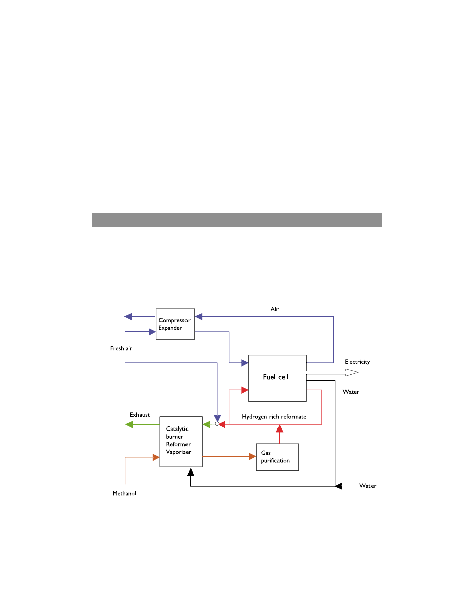
The fuel cell system can be simply structured into the following components: a fuel
processor, an air system, a fuel cell stack and a water and heat management system.
Figure 1 shows a simplified flow chart of the system.
Figure 1. Simplified flow chart of the fuel cell system.

C H E M I C A L E N G I N E E R I N G I N T H E A U T O M O T I V E I N D U S T R Y
5
The fuel, methanol in the case of figure 1, enters the fuel processor where it is converted
into hydrogen. The produced hydrogen reformate is cleaned from by-products that are
hazardous for fuel cell catalysts, like carbon monoxide, in a clean-up system. The cleaned
and moisturized hydrogen-rich reformate is run to the fuel cell’s anode chambers where
the hydrogen is oxidized while oxygen is reduced at the cathode. Water is used to
moisturize hydrogen, since water is transported from the anode to the cathode by
electro-osmosis. Air is supplied to the cell via a compressor. The compressed cathode
chamber exhaust is run through an expander, in order to win back some of the energy
from the compression step. Air is also supplied to the fuel cell processor. The DC-
current produced in the process is transferred to a power conditioner before it is supp-
lied to the electric motor. The spent fuel which still contains some hydrogen, is fed to a
catalytic burner and the heat produced in this combustion process is used in the fuel
processor.
The Fuel Processor and Auxiliary System
The optimal fuel in a fuel cell, from the environmental point of view, is hydrogen
produced by means of renewable sources, such as solar power. However, hydrogen is still
difficult to store in an efficient way, despite extensive research being put into using metal
hydrides and nano fibers.
The storage of hydrogen in alcohols and hydrocarbons is the most effective storage
available today. For automotive applications, hydrogen can be stored efficiently in
methanol. Methanol can be reformed into hydrogen in an external reformer, which is in
essence a tubular reactor. This reformation can be obtained through steam reforming
or partial oxidation
Partial oxidation offers quick start up and, since it is an exothermic reaction, requires
heat dissipation. Steam reforming has a higher rate of conversion, but is a slower process
and, since it is an endothermic reaction, requires heat being supplied to the system. A
combination of both reactions is obtained in the auto-thermal reactor, in which the
reformation reaction gets its heat from the partial oxidation reaction.
The design of the reformer is important for the performance and efficiency of the
total system. It should be able to work at low and high loads, and at high sudden
outputs, e.g., when the car is accelerated. The weight and space taken up by the reactors
should be minimized, and the heat management system optimized for different
operating conditions.
C H E M I C A L E N G I N E E R I N G I N T H E A U T O M O T I V E I N D U S T R Y
6
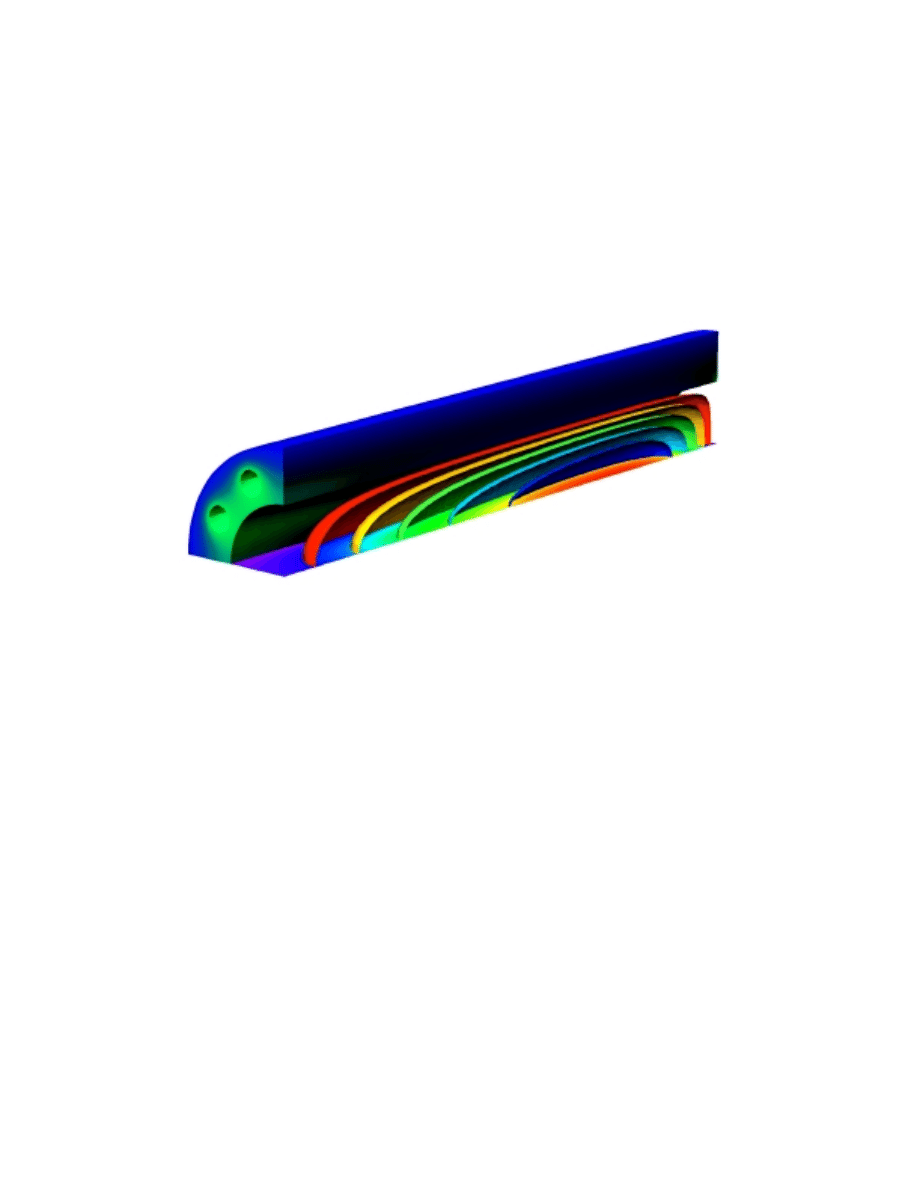
Figure 2 shows the temperature distribution in a tubular reactor for reformation of
methanol to hydrogen through the steam reforming reaction. We can see from this
figure that a jacket heats the reformer while the reactions in the reactor core consume
heat. The curved surfaces in the core represent isothermal surfaces. Different color
scales are used for the heating jacket and for the core, since temperature differences are
significantly larger in the core. The heat is exchanged from the heating channels in the
jacket, through the highly conductive jacket material, and into the core. We can
calculate the temperature profile by defining a heat balance in the reactor, assuming
that heat transfer takes place by conduction and convection.
Figure 2. Simulated temperature profile in the heating jacket and in the core of a steam reforming
reactor.
The hydrogen-rich reformate is supplied to the fuel cell where hydrogen is consumed.
However, to avoid build up of by-products from the processor, and to optimize the
operation of the cell, a surplus of fuel is usually fed to the cell. The exhaust from the
cell is therefore supplied to a catalytic burner and the heat produced in the combustion
process is subsequently used in the fuel processor. The advantage of using a catalytic
burner is that the combustion process takes place at a low temperature thus
minimizing the production of NOx. The catalytic burner might consist of a packed bed
of sintered palladium catalysts.
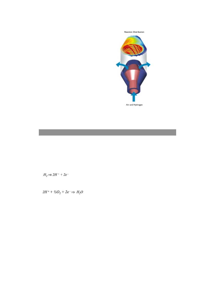
Figure 3 shows the simulated reaction distribution in a catalytic burner. We can
obtain the flow distribution by combining the mass balance with Darcy’s law for flow
through porous media. In this case, we assume that one of the burner walls
accidentally became too thin in the manufacturing process, which results in a non-
uniform flow distribution through the porous catalyst and a non-uniform combustion.
In figure 3, the red color signifies areas of higher combustion rate due to a larger
convective flow of fuel. This might eventually lead to a non-uniform temperature
distribution, and eventually ignition of the gas stream.
C H E M I C A L E N G I N E E R I N G I N T H E A U T O M O T I V E I N D U S T R Y
7
The Electrodes and Electrolyte in the Fuel Cell
A fuel cell works through the principle of separating the oxidation of a fuel, e.g.
hydrogen, and the reduction of oxygen. The oxidation and reduction processes take
place at the anode and cathode respectively, where electrons are released to an outer
circuit at the anode, and received through the same circuit at the cathode.
Anode reaction:
Cathode reaction:
The outer circuit is completed through an external load – the power conditioner
connected to the electric motor – while the transport of protons in the electrolyte
completes the circuit inside the fuel cell, see figure 4. Current is transported through
ionic conduction in the electrolyte, while it takes place through electronic conduction
via the catalysts and electrode backing at the anode and cathode, and the outer circuit.
The electrochemical oxidation and reduction reactions at the anode and cathode serve as
charge transfers between ionic and electronic conduction.
The traditional way of classifying fuel cells is through the composition of its
electrolyte, e.g., a polymeric proton exchange membrane serves as electrolyte in the
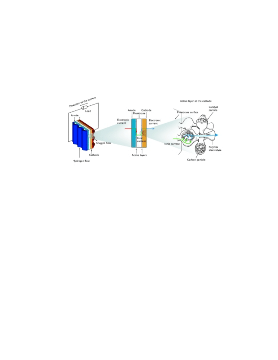
proton exchange membrane fuel cell (PEMFC). Figure 4 shows the principle of the fuel
Figure 3. Dimensionless reaction distribution
in a catalytic burner. Imperfections in the
porous wall of the burner create non-
uniformities in the performance of the burner.
C H E M I C A L E N G I N E E R I N G I N T H E A U T O M O T I V E I N D U S T R Y
8
cell, in this case exemplified by the unit cell of a proton exchange membrane fuel cell.
The electrodes are of gas diffusion type and consist of a supporting carbon structure
with gas-filled pores, and an active layer, which also contains polymer electrolyte and a
solid catalyst. The supporting carbon structure carries the electrons to and from the
active sites in the catalysts. The gas diffusion electrodes are designed to maximize the
specific area available for the reaction, and to minimize the transport resistance of
oxygen and hydrogen to the active sites as well as the resistance for the proton transport
to and from the active sites at the electrodes.
Figure 4. Schematic drawing of a unit cell in the proton exchange membrane fuel cell. The process in
the active layer is exemplified for the cathode reaction.
Oxidation of hydrogen takes place at the active sites of the catalyst and serves as the
charge transfer reaction between electronic and ionic current. The reaction requires
hydrogen, which is transported from the gas-filled pores to the active sites at the catalyst
surface. The hydrogen is converted into protons and electrons. The electrons are
transported through the solid electrode material to the external circuit while the protons
are carried through the proton exchange membrane towards the cathode. At the
cathode, the protons react with electrons supplied by the solid catalyst, and oxygen, to
produce water. Oxygen has to be supplied to the reaction site from the gas-filled pores
through the polymer electrolyte incorporated in the active layer.
We can detect an optimization problem in the design of the cathode. Oxygen has to
diffuse to the reaction site while, at the same time, polymeric electrolyte is required to
transport the protons to the same site. In order to minimize the oxygen transport
resistance, its path through the polymer has to be as short as possible, while keeping
sufficient polymer material in order to reduce resistance for the ionic current transported
by protons.
The oxygen concentration inside and around catalyst agglomerates is shown in figure
5. We can see that substantial concentration gradients arise in the polymer electrolyte at
high loads, inside the electrode. Modeling can serve as a powerful tool when
investigating the distribution of catalyst and polymer electrolyte within the active layer of

C H E M I C A L E N G I N E E R I N G I N T H E A U T O M O T I V E I N D U S T R Y
9
fuel cell electrodes. The simulations give a hint of the degree of utilization of the
expensive catalyst in the electrode. In figure 5, we can see a projection of two catalyst
agglomerates, covered by a thin film of polymer electrolyte. The agglomerates form a
neck, where the polymer electrolyte forms a meniscus, which additionally increase the
oxygen transport resistance. The model is highly idealized but the described
phenomenon is realistic. We treat the model in 2-D by introducing rotational
symmetry and cylindrical coordinates.
Figure 5. Oxygen concentration distribution around and inside two catalyst agglomerates in a fuel
cell cathode.
Potential distribution in a fuel cell
Once the protons are produced at the reaction sites, they are transported away from the
anode by means of migration in the electrical field. The protons are thus transported
from the negative electrode to the positive electrode, i.e., apparant in the opposite
direction to the electric field. However, the electric field inside the fuel cell is reversed
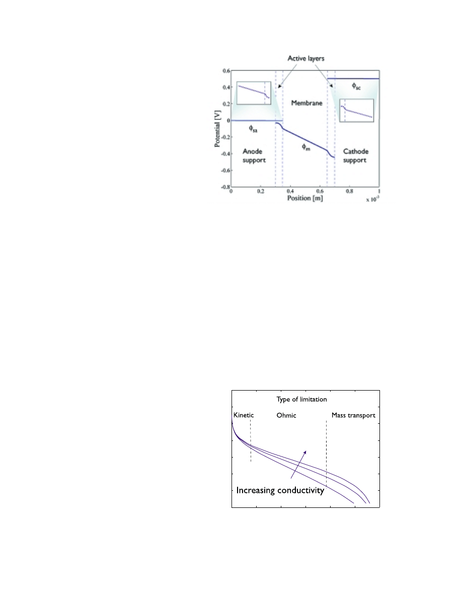
during the discharge process. This is shown in figure 6 where the potential through the
cell is drawn schematically. The potential is reversed through the discontinuity in
potential at the interface between the solid catalyst and the polymer electrolyte. This
discontinuity is a part of the total overpotential, and is partly given by the activation
energy for the electron transfer between the electrolyte and catalyst. Since one of the
reactants is the electron, we can change its free energy in the electrode by changing the
potential, which also changes the activation energy for the electron transfer reaction. We
can see that the potential in the active layer shows curvature, which is typical for the
presence of sinks or sources.
C H E M I C A L E N G I N E E R I N G I N T H E A U T O M O T I V E I N D U S T R Y
10
0
2000
4000
6000
8000
10000
12000
0
0.2
0.4
0.6
0.8
1
1.2
1.4
Current Density [A/m
2
]
Cell Voltage [V]
Figure 6. Sketch of the
potential profile through
the fuel cell when a load is
applied to the outer
circuit.
The oxygen reduction reaction, which takes place at the active sites of the catalysts, serves
as the charge transfer reaction between ionic and electronic current. This cathode
reaction requires oxygen obtained from the gas-filled pores, protons from the proton
exchange membrane electrolyte, and electrons from the solid catalyst. The produced
water has to be carried away from the electrode, which is done through evaporation.
The proton exchange membrane needs to be moist in order to conduct ionic current
properly. The protons drag water molecules on their way from the anode to the cathode
by electro-osmosis. In order to keep the membrane wet, the hydrogen stream entering
the anode chamber is humidified. Figure 7 shows the influence of membrane conductivity
on the polarization of the unit cell.
Figure 7. Polarization of the unit cell
for different membrane conductivities.
C H E M I C A L E N G I N E E R I N G I N T H E A U T O M O T I V E I N D U S T R Y
11
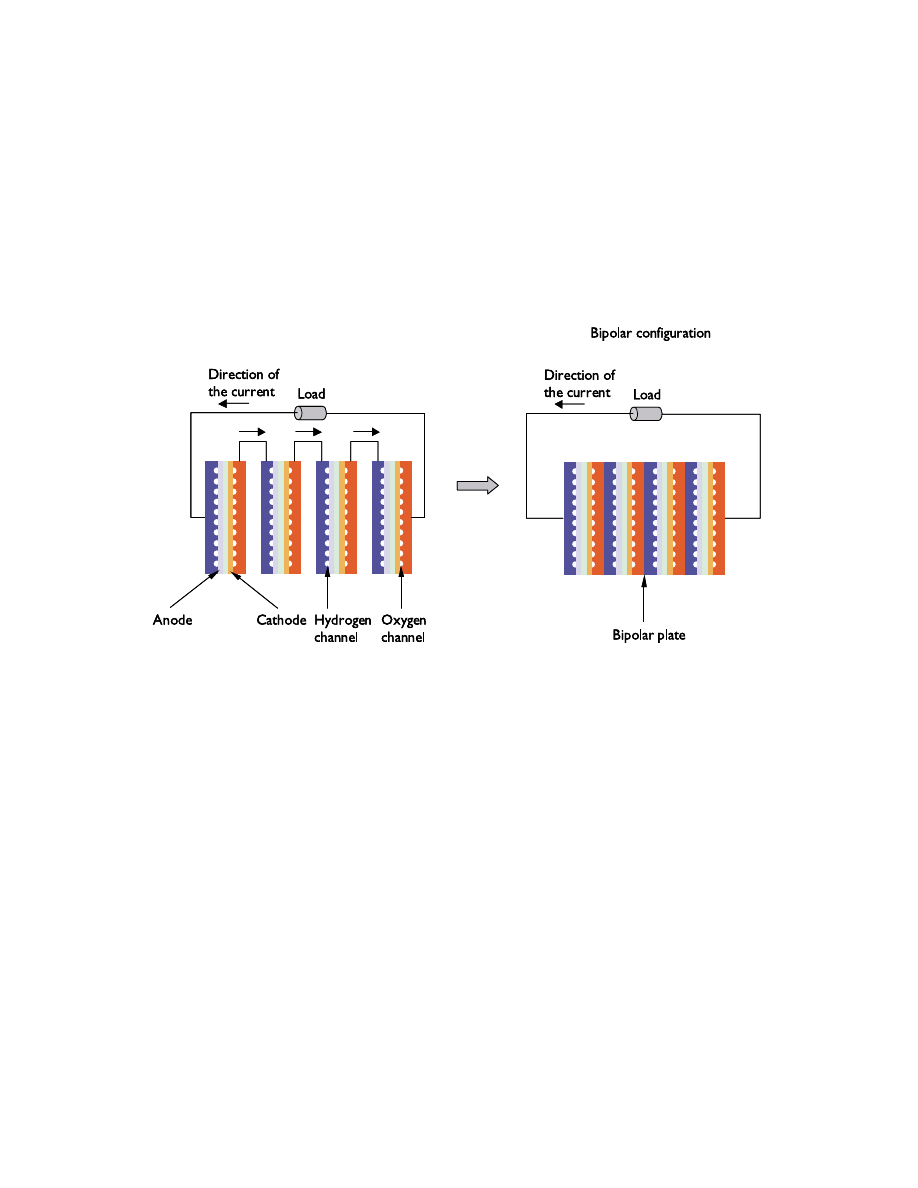
One unit cell produces, roughly, 2 kA/m
2
at a cell voltage of 0.8 V. This implies that we
have to couple several cells in series in order to increase the voltage to usable levels. This
is done in a fuel cell stack, where bipolar plates serve both as separators and current
conductors between adjacent anodes and cathodes. These bipolar plates also serve as gas
suppliers to the electrodes through channels in their structure. In addition, the edges of
the plates serve as manifolds for the fuel cell stack. Figure 8 shows the principle behind a
bipolar stack.
Figure 8. Sketch of a bipolar fuel cell stack.
The design of the bipolar plate is very important for the performance of the fuel cell
stack. The plates must be capable of effectively distributing gas to minimize mass
transport limitations, while at the same time providing the path for electronic current.
Figure 9 shows the potential distribution in the contact area between the electrode and
the bipolar plate. Contact resistance should be minimized and, if the bipolar plate is
made of a metallic material, it is important that low-conducting oxide layers are not
formed between the electrode and plate. The color scales in the figure are different for
the plate and electrode due to a large difference in conductivity between the two
materials. We can use models like the one shown in figure 9 to investigate the influence
of bipolar plate design on the cell performance.

C H E M I C A L E N G I N E E R I N G I N T H E A U T O M O T I V E I N D U S T R Y
12
The Near Future
The fuel cell driven car is today a reality for production in small series and concept cars.
The cost of the materials that are presently used are still too high for mass production.
However, the large automotive companies have shown a true commitment in solving
these problems and they forecast production at an industrial scale within three years.
This implies that some of the buses and cars in our urban areas will soon be fuel cell
driven. We believe that modeling will contribute to the success of this mission. We also
hope that Femlab will be able to contribute in this work.
Figure 9. Potential distribution
at the contact zone between a
bipolar plate and the electrode
backing in a fuel cell stack. The
color scale that goes from green to
yellow represents the potential in
the metallic plate, while the color
scale that goes from blue to red
represents the potential in the
electrode.

C H E M I C A L E N G I N E E R I N G I N T H E A U T O M O T I V E I N D U S T R Y
13
References
Dr. Ed Fontes
is Product Manager at COMSOL AB. He was previously the Manager of the
Electrolysis group at Eka Chemicals R&D in Sundsvall, Sweden. He made his Ph.D.
on modeling gas diffusion electrodes in fuel cells.
Dr. Eva Nilsson
is a consultant in the field of battery and fuel cell technology at Catella Generics AB,
Stockholm, Sweden. She made her Ph.D. on modeling electrochemical processes in
biological systems.

COMSOL, Inc.
8 New England Executive Park
Suite 310
Burlington, MA 01803
Tel: 781-273-3322
Fax: 781-273-6603
Email: info@comsol.com
Web:www.comsol.com
Wyszukiwarka
Podobne podstrony:
Hydrogen Understanding Fuel Cells
Engineering Residential Fuel Cells Ebook
FORTE WP Fuel FINAL
metody WP
wp-yw szkoly na rozwoj dziecka, UCZELNIA
BADANIE WP YWU ST ENIA NA SZYBKO REAKCJI CHEMICZNYCH
biogas as vehicle fuel id 87120 Nieznany
4 Fuel and Lubrication System
08 fuel system
Przygoda z usmiechem WP 3 latki cz 1 scenariusz tydz 15
Leki wp
Przygoda z usmiechem WP 3 latki cz 2 scenariusz tydz 25
Przygoda z usmiechem WP 3 latki cz 2 scenariusz tydz 29
05 Fuel System
Bosch Motorsport com HDP 5 Fuel Pump
więcej podobnych podstron