
CORRECTION OF APERTURE ABERRTIONS
OF HYBRID LENS
Marek ZAJĄC and Jerzy NOWAK
Instytute of Physics, Technical University of Wrocław
Wybrzeże Wyspiańskiego 27, PL 50-370 Wrocław, Polska
E-mail: zajac@if.pwr.wroc.pl
ABSTRACT
The possibilities of aberration correction in the case of a single lens are limited. It is well known that,
if classic glasses are used, it is impossible to compensate spherical aberration. It can be, however,
minimised by proper choice of the ratio between the first and second surface radii of curvature (referred
here as
ζ). It is possible also, in cost of uncorrected spherical aberration, to compensate III order coma.
Additional possibilities of aberration correction occur, however, if a thin diffractive structure is deposited
on one of the lens surface. Such lens is usually referred as a hybrid (diffractive-refractive) lens. The
diffractive structure typically corresponds to the holographic lens generated by the interference of two
spherical waves. The ratio of these waves radii of curvature is treated as a parameter (called here
β)
describing fully aberration properties of this structure. A focusing power of the diffractive part typically
is only a small fraction (
η ) of total focusing power of a hybrid lens, so the diffractive part acts mainly as
aberration corrector. Aberration properties of hybrid lens are determined by two parameters:
ζ and β so it
is possible to achieve simultaneous correction of aperture aberrations: spherical aberration and coma.
In the paper formulas describing the III-order aberration coefficients were used for calculating the
values of parameters
ζ and β assuring such correction for several values of parameter η and different
locations of object plane. The calculations were performed with help of the MATHCAD programme.
Basing on the results a number of hybrid lenses (collimating and imaging) were designed. Their imaging
quality was then evaluated by numerical calculation of aberration spots. Estimated values of such image
characteristics as the aberration spot moment of inertia or third order moment of the spots distribution
enable to compare the imaging quality. The essential improvement of imaging quality for the investigated
lenses (F-number equal to 1:10, maximum field angle 0.06) is achieved.
1. INTRODUCTION
In some applications it might be useful to use as simple optical imaging element as possible.
Unfortunately the imaging quality of single spherical lens is fairly unsatisfactory. It is well known, that (if
classic glasses are used) it is impossible to correct spherical aberration, which can be only minimized.
Additional possibility of aberration correction occurs, however, if the diffractive structure is deposited on
one of the lens surfaces. Such lens is usually referred as a hybrid (diffractive-refractive) lens. The
diffractive structure typically is manufactured synthetically but its geometry corresponds to the
holographic lens generated by the interference of two spherical waves. Thus additional parameters
enabling to correct aberrations appear when using a hybrid lens.
As it was pointed out above, the hybrid lens is understood as a conventional glass lens with a
diffractive structure deposited on one of its surfaces. The diffractive power of the hybrid lens is splitted
between the diffractive and refractive parts. The diffractive part plays the role of an aberration corrector,
so its refractive power can be only a small fraction of the total focusing power. Therefore the average
2
spatial frequency of diffractive structure can be relatively low which enables its manufacturing in a
typical interferometric laboratory or synthetically by printing with typical computer equipment (e.g. laser
printer).
The imaging properties of hybrid lenses were investigated extensively and described in the literature
[1-5]. For example, an analysis of sphero-chromatic aberration has been performed in [6, 7], from which
it follows that due to relatively large secondary spectrum such lens may be applied mainly in
quasi-monochromatic light. The possibilities of aplanatic correction of hybrid lens was discussed by the
authors of the present publication in the paper [8]. There they showed that for plano-convex hybrid lens
with diffractive structure deposited on the first (plane) surface, the correction of coma is possible only if
the real object is located at the distance
'
04
.
2
f
z
≤
; hence a lens focusing parallel light beam cannot be
aplanatic. In the paper [9] they investigated the aberrations of plano-convex hybrid lens with a diffractive
structure deposited on the second surface. In such case it is possible to obtain aplanatic correction even
for the object in infinity. In the present paper a hybrid lens of general shape is investigated.
2. ANALYTICAL RELATIONS
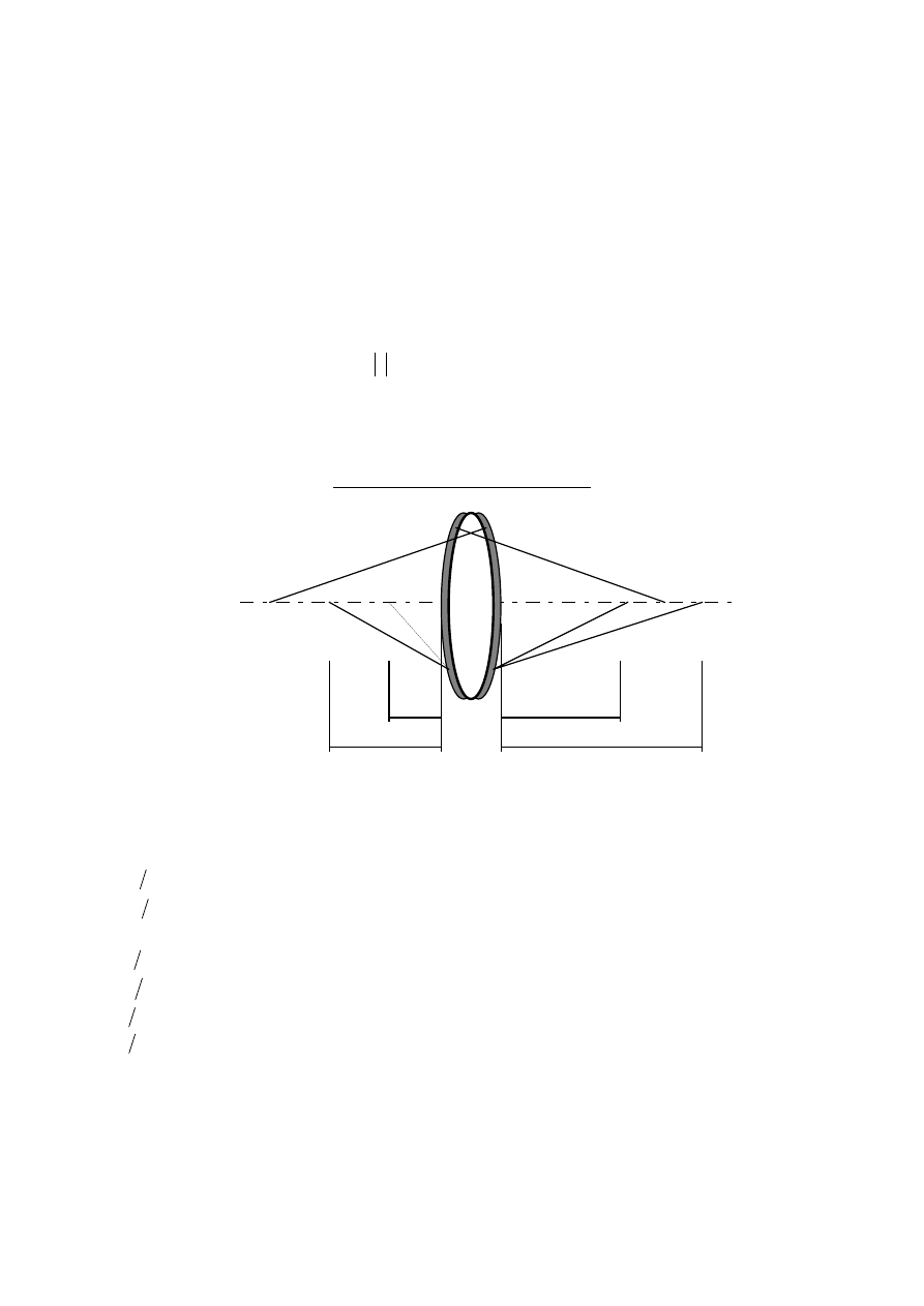
Fig. 1 Geometry parameters of hybrid lens
The hybrid lens under investigation is presented in the Fig. 1. The notation used there, as well as in the
following text is:
1
1
1
ρ
ρ
=
V
- curvature of the first refractive surface,
2
2
1
ρ
ρ
=
V
- curvature of the second refractive surface,
n
- refractive index of a lens material,
α
α
z
V
1
=
- wavefront curvature of the first wave creating the diffractive structure
β
β
z
V
1
=
- wavefront curvature of the second wave creating the diffractive structure
z
V
1
=
- reciprocity of the distance from the object point to the lens,
'
1
'
z
V
=
- reciprocity of the distance from the lens to the image point,
µ
±
- ratio of the imaging wavelength and the "recording wavelength" (+ sign corresponds to
the primary image, - sign to the secondary one).
ρ1
ρ2
Ζα1
Ζβ1
Ζα2
Ζβ2
n

3
Distances
α
z
and
β
z
are not necessarily connected to physically existing point light sources (as in a
lens manufactured holographically), but rather are treated as parameters.
In order to describe aberrations of the hybrid lens, the most convenient method seems to be proposed
by VERBOVEN and MASAJADA [10, 11]. After [12] we can express the coeficients of the III-order
aberrations, in the general case of a hybrid lens with diffractive microstructure deposited on both
surfaces. The coefficients of third order spherical aberration and coma (only meridional cross-section and
infinitely thin lens is considered) have the form.
(
)
[
]
(
)
+
−
−
+
+
+
−
−
−
=
1
1
1
1
1
1
1
2
1
n
V
V
n
n
V
V
S
R
D
D
R
R
ϕ
ϕ
ϕ
ϕ
ϕ
(
)
(
)
+
−
−
+
+
−
2
2
1 n
V
V
ρ
ϕ
ϕ
ϕ
[
]
(
)
+
−
−
+
+
+
+
n
n
V
V
n
R
D
R
D
R
1
1
2
1
1
1
1
2
ϕ
ϕ
ϕ
ϕ
ϕ
(
)
(
) (
)
(
) (
)
+
−
−
−
±
−
−
−
−
±
−
+
2
1
1
1
1
1
1
2
1
1
1
1
1
1
1
1
1
1
1
β
ϕ
β
µ
β
ϕ
β
β
ϕ
β
µ
ϕ
β
ϕ
R
D
R
D
D
(
)
(
) (
)
(
) (
)
−
−
−
±
−
−
−
−
±
−
+
2
2
2
2
2
2
2
2
2
2
2
2
2
2
1
1
1
1
1
β
ϕ
β
µ
β
ϕ
β
β
ϕ
β
µ
ϕ
β
ϕ
R
D
R
D
D
(1)
(
) (
) (
)
−
+
+
+
−
+
−
+
+
+
−
−
=
1
1
1
1
2
1
1
1
2
n
V
V
n
n
V
n
V
V
yV
C
R
R
R
R
D
R
y
ϕ
ϕ
ϕ
ϕ
ϕ
ϕ
ϕ
ϕ
(2)
where
1
1
1
α
β
β
V
V
=
,
(3)
2
2
2
α
β
β
V
V
=
,
(4)
and
(
)
1
1
1
ρ
ϕ
V
n
R
−
=
(5)
(
)
2
2
1
ρ
ϕ
V
n
R
−
=
(6)
(
)
1
1
1
β
α
µ
ϕ
V
V
D
−
±
=
(7)
(
)
2
2
2
β
α
µ
ϕ
V
V
D
−
±
=
(8)
are focusing powers of first and second refractive surfaces and first and second diffractive structure,
respectively. Coefficient
µ typically equals 1, and is omitted in the following.
Obviously the total focusing power of a hybrid lens is
2
1
2
1
D
D
R
R
ϕ
ϕ
ϕ
ϕ
ϕ
+
+
+
=
(9)
For the sake of simplicity new parameter describing the hybrid lens are introduced:
2
1
2
1
R
R
D
D
R
D
ϕ
ϕ
ϕ
ϕ
ϕ
ϕ
η
+
+
=
=
(10)

4
This parameter determines a fraction of the overall refractive power due to the diffractive corrector.
Additionally it is set
1
2
R
R
ϕ
ϕ
ζ
=
(11)
and:
ϕ
V
v
=
(12)
Using this notation formula (2) expressing coma changes to:
(
)(
)(
)
+
+
+
−
−
=
η
ζ
ϕ
η
ζ
ϕ
1
1
1
1
1
)
,
,
,
,
(
2
1
n
v
n
v
C
(13)
(
)(
) (
)
(
)
(
)(
)(
)
(
)
(
)(
)(
)
+
+
−
−
+
+
−
+
+
−
+
+
+
+
+
+
η
ζ
ζ
η
ζ
ζ
η
η
η
ζ
1
1
1
1
1
1
1
1
1
1
1
1
1
n
v
v
n
n
v
if the diffractive strusture is deposited on the first surface, and
(
)(
)(
)
+
+
+
−
−
=
η
ζ
ϕ
η
ζ
ϕ
1
1
1
1
1
)
,
,
,
,
(
2
2
n
v
n
v
C
(14)
(
)(
)
(
)
(
)(
)(
)
(
)
(
)(
)(
)
+
+
−
−
+
+
−
+
+
−
+
+
+
+
η
ζ
ζ
η
ζ
ζ
η
ζ
1
1
1
1
1
1
1
1
1
1
1
1
n
v
v
n
n
v
if it is located on the second surface of the hybrid lens.
It is easy to note, that coma does not depend on the properties of the diffractive part (eqs. 13 and 14 do
not include parameter
β1 nor β2), but it depends only on the fraction of the total focusing power η of this
part.
For given refractive index n and total focusing power
ϕ it is possible to calculate the shape of
refractive part of the hybrid lens assuring coma correction in dependency on the object location v and the
parameter
η. It is determined by the value of parameter ζ from which the radii of its both surfaces of the
refractive part of a hybrid lens can be calculated
(
)(
)(
)
ϕ
η
ζ
ρ
n
−
+
+
=
1
1
1
1
(15)
and
5
(
)(
)(
)
ϕζ
η
ζ
ρ
n
−
+
+
=
1
1
1
2
(16)
0
5
10
0
10
20
30
40
50
0
10
20
30
ζζ 1
0
5
10
0
10
20
30
40
50
0
5
10
15
20
ζζ 2
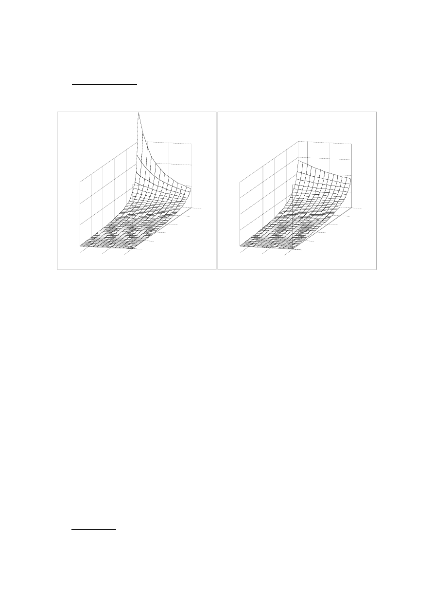
Fig.2 Condition for correction of coma. Parameter
ζ vs object location v and parameter η
Necessary calculations were performed with help of the Mathcad program and are presented on the
graphs shown in the Figure 2. The considered object location varies from minus infinity (focusing lens) to
the front focal length (collimating lens). The corresponding values of the parameter v vary thus from
0 to -1. Parameter
η determining the diffractive corrector focusing power is assumed to vary from zero
(pure refractive lens) to 12% which is treated as a limit.
The formula describing the spherical aberration (1) is more complicated, but the Mathcad program
enables to handle it. After symbolic solution of the equations
0
)
,
,
,
,
(
1
=
η
ζ
ϕ
n
v
C
and
0
)
,
,
,
,
(
2
=
η
ζ
ϕ
n
v
C
with respect to the value of
ζ (assuming v and η as parameters) and substituting the result into (1) the
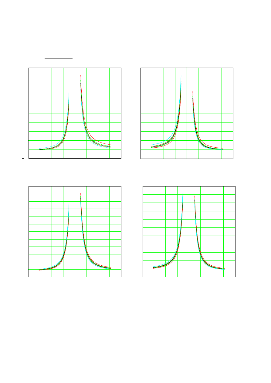
relation between the spherical aberration and the value of parameter
β characterizing the geometry of
diffractive structure may be determined. Fig. 3a-d present the exemplary curves illustrating the spherical
aberration vs parameter
β for different object point locations and ratio η if the diffractive corrector is
located on the first or second surface of the hybrid lens. It can be seen that for each investigated case two
solutions exist.
Taking the value of
β for which spherical aberration equals to zero leads to aplanatic hybrid lens. The
value of parameter
β determines the geometry of diffractive structure deposited on the refractive part as it
is
(
)(
)
ϕη
η
β
α
+
−
=
1
1
z
(17)
6
and
(
)(
)
ϕηβ
η
β
β
+
−
=
1
1
z
(18)
0.96 0.97 0.98 0.99 1
1.02 1.03 1.04
4
0
4
8
12
16
β
1.01
S
a)
1.04
4
8
12
16
1
1.01
-4
0
1.02
1.03
0.99
0.98
0.97
0.96
β
S
b)
0.96 0.97 0.98 0.99
1
1.01 1.02 1.03 1.04
10
0
20
40
60
80
100
β
-
S
c)
0.96 0.97 0.98 0.99
1
1.01 1.02 1.03 1.04
10
0
20
40
60
80
100
S
β
-
d)
Fig. 3
Spherical aberration vs parameter
β, for different locations of object plane
(
1
,
,
,
,
3
2
2
1
3
1
−
−
−
−
−∞
=
v
),
a) diffractive corrector on the first surface,
05
.
0
=
η
b) diffractive corrector on the second surface,
05
.
0
=
η
7
c) diffractive corrector on the first surface,
10
.
0
=
η
d) diffractive corrector on the second surface,
10
.
0
=
η
As it could be expected there is no solution for
β if the fraction η tends to zero, but the solutions for
05
.
0
=
η
and
10
.
0
=
η
are presented in the Fig. 4
v
β
0,94
0,96
0,98
1
1,02
1,04
1,06
1,08
-1
-0,9
-0,8
-0,7
-0,6
-0,5
-0,4
-0,3
-0,2
-0,1
0
eta=0.05 I surface
eta=0.10 I surface
eta=0.05 II surface
eta=0.10 II surface
Fig. 4 Condition for simultaneous correction of coma and spherical aberration. Parameter
β vs object
location v for diffractive corrector on the first or second surface and two values of parameter
η
(
05
.
0
=
η
and
10
.
0
=
η
)
3. NUMERICAL ILLUSTRATION
To illustrate the obtained results several examples of aplanatic lenses were choosen and their imaging
quality was analysed. Focal length of all lenses was assumed to be
mm
f
100
'
=
and relative F-number to
1:10. The value of the lens material refractive index was taken as
5
.
1
=
n
. Two arbitrarily choosen values
of parameters determining the ratio of diffractive corrector focusing power to the total hybrid lens
focusing power were chosen:
05
.
0
=
η
, and
10
.
0
=
η
. Three imaging geometries were investigated:
object point was located in minus infinity (collimating lens), as well as in dostance
f
z
3
−
=
(magnification = -1/2) and
f
z
2
−
=
(magnification = -1). For comparison two pure refractive lenses of
the same imaging characteristics were investigated. One of them has compensated coma, the other -
minimized spherical aberration.

8
Geometry parameters of all chosen lenses are given in the Tables 1-3
Table 1
Geometry parameters characterizing the analysed lenses
(collimating lens - object in infinity)
No
ζ
R1 [mm] R2 [mm]
β
zβ [mm] zα [mm]
remarks
R10
55.555
-500.00
-
-
-
refractive lens,
coma corrected
R20
58.824
-333.33
-
-
-
refractive lens, spherical
aberration minimized
P10 0.094871
57.481
-605.88 1.018485
or
0.09489
-38.819
or
20.233
-38.114
or
20.430
hybrid lens,
05
.
0
=
η
diffractive corrector on
the first surface
P20 0.072079
56.284
-780.88 1.012345
or
0.987245
-25.925
or
26.785
-25.608
or
27.132
hybrid lens,
05
.
0
=
η
diffractive corrector on
the second surface
S10 0.07833
59.308
-757.16 1.062085
or
0.976095
-68.293
or
26.295
-64.301
or
26.939
hybrid lens,
10
.
0
=
η
diffractive corrector on
the first surface
S20 0.03617
56.989
-1576.0 1.033925
or
0.966155
-37.317
or
37.230
-36.093
0r
38.534
hybrid lens,
10
.
0
=
η
diffractive corrector on
the second surface
Table 2
Geometry parameters characterizing the analysed lenses
(imaging lens, object distance
f
z
3
−
=
)
No
ζ
R1 [mm] R2 [mm]
β
zβ [mm] zα [mm]
remarks
R11
78.947
-136.36
-
-
-
refractive lens,
coma corrected
R21
59.322
-318.18
-
-
-
refractive lens, spherical
aberration minimized
P11 0.584006
83.160
-142.40 1.015795
or
0.989795
-33.170
or
21.431
-32.654
or
21.651
hybrid lens,
05
.
0
=
η
diffractive corrector on
the first surface
P21 0.53674
80.679
-150.31 1.011145
or
0.986125
-23.404
or
26.785
-23.147
or
27.132
hybrid lens,
05
.
0
=
η
diffractive corrector on
the second surface

9
S11 0.58765
87.319
-148.60 1.048145
or
0.974075
-52.960
or
28.517
-50.527
or
29.276
hybrid lens,
10
.
0
=
η
diffractive corrector on
the first surface
S21 0.49788
82.383
-165.468 1.029605
or
0.961495
-32.566
or
42.356
-31.629
or
44.052
hybrid lens,
10
.
0
=
η
diffractive corrector on
the second surface
Table 3
Geometry parameters characterizing the analysed lenses
(imaging lens, object distance
z
f
= −2
)
No
ζ
R1 [mm] R2 [mm]
β
zβ [mm] zα [mm]
remarks
No
ζ
R1
[mm]
R2
[mm]
β
zβ
[mm]
zα
[mm]
remarks
R12
100.00
-100.00
-
-
-
refractive lens,
coma corrected
R22
59.322
-318.18
-
-
-
refractive lens, spherical
aberration minimized
P12 1.039604
107.08
-103.00 1.014845
or
0.989415
-31.174
or
22.228
-30.718
or
22.466
hybrid lens,
η = 0 05
.
diffractive corrector on
the first surface
P22 0.96190
375.00
-107.08 1.010695
or
0.985375
-22.459
or
30.712
-22.222
or
31.168
hybrid lens,
η = 0 05
.
diffractive corrector on
the second surface
S12 1.07843
114.31
-106.00 1.043655
or
0.972775
-48.020
or
29.95
-46.012
or
30.786
hybrid lens,
η = 0 10
.
diffractive corrector on
the first surface
S22 0.92727
106.00
-114.312 1.027985
or
0.958165
-30.783
or
46.018
-29.945
or
48.028
hybrid lens,
η = 0 10
.
diffractive corrector on
the second surface
The imaging quality was evaluated by typical ray-tracing computer simulation. In the Figs. 5 - 10 spot
diagrams for the lenses R12, R22, P12, S12 are presented for the field angles equal to
0
=
z
y
, and
04
.
0
=
z
y
. The circle containing 80% total number of ray traces (considered as 80% total light spot
energy) is marked on the graphs.

10
Fig 5 Aberration spots for the lens No.R11 (refractive, coma corrwected)
field angles
04
.
0
,
0
=
z
y
Fig 6 Aberration spots for the lens No.R21 (refractive, minimum spherical aberration)
field angles
04
.
0
,
0
=
z
y
Fig 7 Aberration spots for the lens No.S11 (hybrid, diffractive corrector on first surface,
η=0.05)
field angles
04
.
0
,
0
=
z
y

11
Fig 8 Aberration spots for the lens No.S12 (hybrid, diffractive corrector on second surface,
η=0.05)
field angles y z
= 0 0 04
, .
Fig 9 Aberration spots for the lens No.P11 (hybrid, diffractive corrector on first surface,
η=0.10)
field angles y z
= 0 0 04
, .
Fig 10 Aberration spots for the lens No.P12 (hybrid, diffractive corrector on second surface,
η=0.10)
field angles
04
.
0
,
0
=
z
y
Several parameters characterising aberration spots were calculated from the spot diagrams:
12
8
.
0
d
- diameter of a light spot containing 80% of total energy,
2
M
- second order moment of the light intensity distribution in the aberration spot being the measure of
its spread:
(
)
∑
=
−
=
N
i
i
y
y
y
N
M
1
2
2
1
(19)
3
M - third order moment of the light intensity distribution in the aberration spot being the measure of its
non symmetry according to the spot centre of gravity y :
(
)
∑
=
−
=
N
i
i
y
y
y
N
M
1
3
3
1
(20)
RMS
- mean square deviation of the rays distribution the spot diagram being the measure of the rays
distribution (similar as
M
2
):
(
) (
)
[
]
∑
=
−
+
−
=
N
i
i
i
y
y
y
y
N
RMS
1
2
2
1
(21)
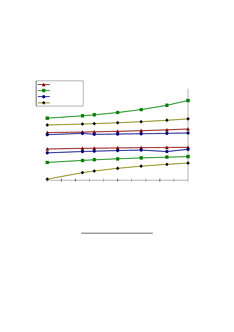
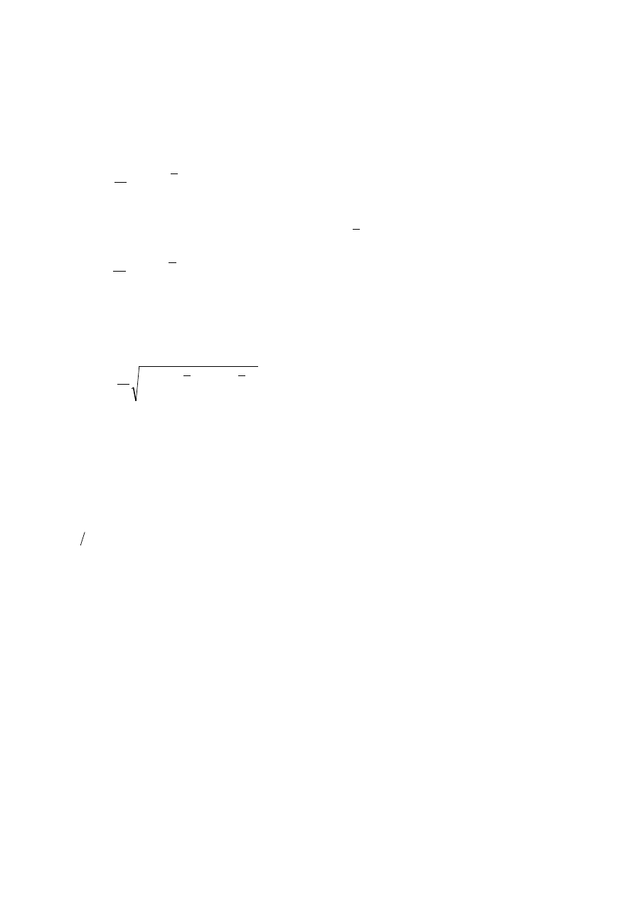
Values of these parameters versus field angle for all investigated lenses are presented in the Fig. 11, 12,
13 and 12. From these pictures it is evident, that imaging quality of all hybrid lenses is practically the
same.
The analysis of the obtained results confirms that it is possible to obtain the aplanatic correction for
simple hybrid lens. The assumption, that one of the surface is flat is not necessary. Diffractive corrector
can be located on either first or second surfsce as well. There is no limitation for the object location. The
imaging quality is considerably better, than for corresponding classic lens. Field curvature and
astigmatism remains uncorrected, as it was expected. The image is acceptable for the field angle not less
than
05
.
0
=
z
y
, what is satisfactory for one-piece optical element.
13
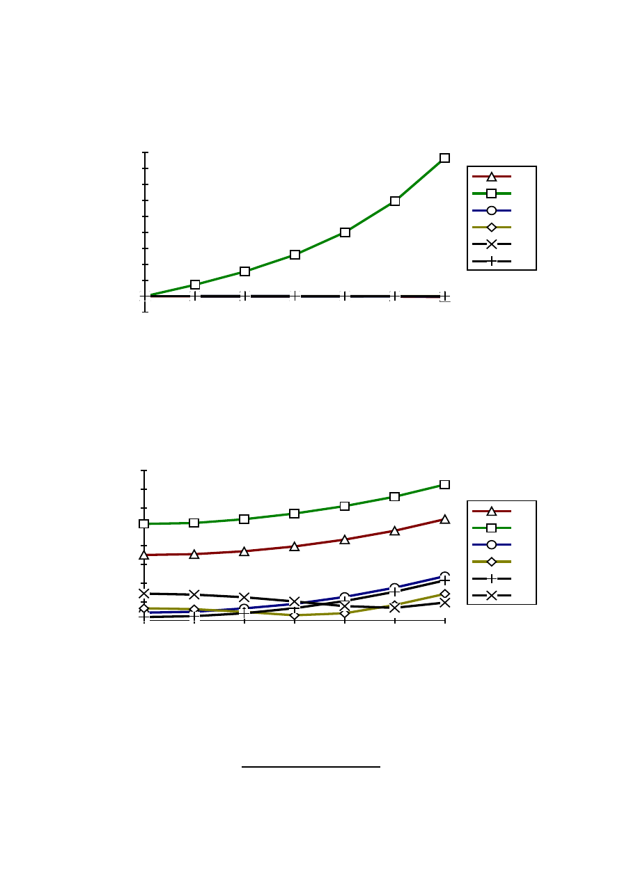
d08
0,00E+00
5,00E-02
1,00E-01
1,50E-01
2,00E-01
2,50E-01
3,00E-01
3,50E-01
0
0,01
0,02
0,03
0,04
0,05
0,06
R12
R22
P12
P22
S12
S22
Fig. 11 Diameter of a light spot containing 80% of total energy (
8
.
0
d ) vs field angle for imaging lens
of magnification -1 (v = -0.5, object distance z = -2f).
R12, R22 - pure refractive lenses,
P12, P22 - hybrid lenses with corrector of
η = 0.05,
S12, S22 - hybrid lenses with corrector of
η = 0.10.
M2
0,00E+00
1,00E-02
2,00E-02
3,00E-02
4,00E-02
5,00E-02
6,00E-02
7,00E-02
0
0,01
0,02
0,03
0,04
0,05
0,06
R12
R22
P12
P22
S12
S22
Fig. 13 Second order moment of the light intensity distribution in the aberration spot (
2
M
) vs field
angle for imaging lens of magnification -1 (v = -0.5, object distance z = -2f).
R12, R22 - pure refractive lenses,
P12, P22 - hybrid lenses with corrector of
η = 0.05,
S12, S22 - hybrid lenses with corrector of
η = 0.10.
14
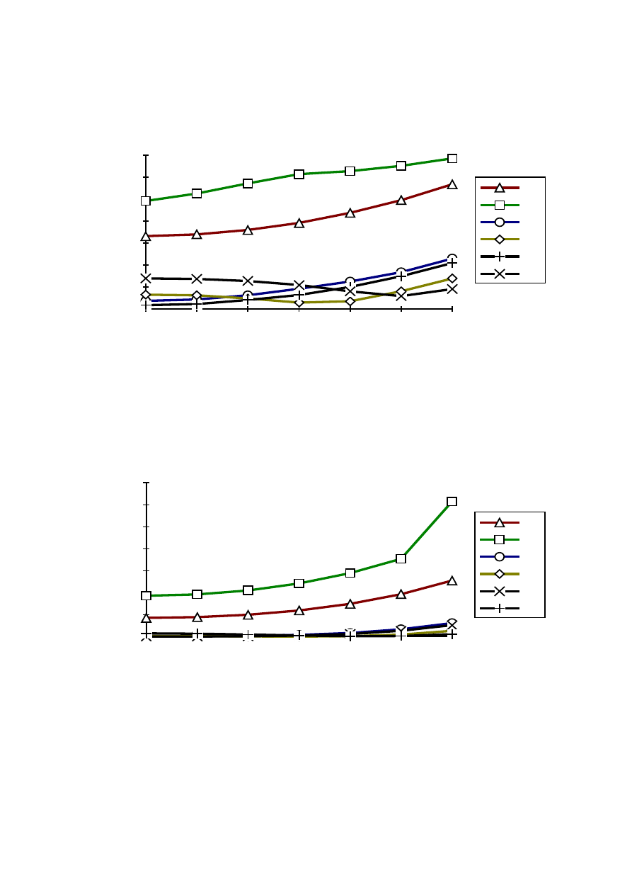
M3
-1,00E-03
0,00E+00
1,00E-03
2,00E-03
3,00E-03
4,00E-03
5,00E-03
6,00E-03
7,00E-03
8,00E-03
9,00E-03
0
0,01
0,02
0,03
0,04
0,05
0,06
R21
R22
P12
P22
S12
S22
Fig. 14 Third order moment of the light intensity distribution in the aberration spot (M
3
) vs field
angle for imaging lens of magnification -1 (v = -0.5, object distance z = -2f).
R12, R22 - pure refractive lenses,
P12, P22 - hybrid lenses with corrector of
η = 0.05,
S12, S22 - hybrid lenses with corrector of
η = 0.10.
RMS
0,00E+00
2,00E-03
4,00E-03
6,00E-03
8,00E-03
1,00E-02
1,20E-02
1,40E-02
1,60E-02
0
0,01
0,02
0,03
0,04
0,05
0,06
R12
R22
P21
P22
S12
S22
Fig. 12 Mean square deviation of the rays distribution the spot diagram (
RMS
) vs field angle for
imaging lens of magnification -1 (v = -0.5, object distance z = -2f).
R12, R22 - pure refractive lenses,
P12, P22 - hybrid lenses with corrector of
η = 0.05,
S12, S22 - hybrid lenses with corrector of
η = 0.10.
ACKNOWLEDGMENTS

15
This publication was supported by Committee for Scientific Research (KBN) under the contract
No. 34165-7
REFERENCES
1 S. Bobrov, G. Greisukh, Yu. Turkavich, "Optika diffraktsionnykh elementov i sistem" [ in Russian],
Mashinostroenie, Leningrad 1986;
2 E. Jagoszewski, " Holograficzne elementy optyczne" [ in Polish], Oficyna Wydawnicza
Politechniki Wrocławskiej, Wrocław 1995;
3 N, C. Gallagher, SPIE Proc., 1396, 722-733 (1992);
4 A. P. Wood, Appl. Optics, 31, 2377-2384 (1992);
5 M. Larson, C. C. Beckman, A. Nystrom, S. Hard, J. Sjostrand, Appl. Optics, 31, 2377 -2384 (1992);
6 N. Emerton, Proc. III Int. Conf. on Holographic Systems, Components and Applications,
Edinburgh, 1991,
7 B. Dubik, S. Koth, J. Nowak. M. Zając, Optics and Laser Technology, 27, 315 (1995),
8 S. Koth, J. Nowak M. Zając, Pure and Applied Optics, 4, 543-552, (1995);
9 S. Koth, J. Nowak, M. Zając, Opt. Applicata, 25, 245 (1995),
10 P. E. Verboven, P. E. Lagasse, Appl. Opt. 25, 1791-1795 (1991);
11 J. Masajada, J. Nowak, Appl. Opt. 30, 1791-1795 (1991);
12 B. Dubik, S. Koth, M, Zając, SPIE Proc 2169, 130-137 (1993).
Wyszukiwarka
Podobne podstrony:
Correction Of Chromatic Abberration In Hybrid Objectives
DESIGN OF HYBRID PHOTOVOLTAIC POWER GENERATOR, WITH OPTIMIZATION OF ENERGY MANAGEMENT
1The effects of hybridization on the abundance of parental taxa depends on their relative frequency
E E (Doc) Smith Lensman 06 Children of the Lens
Effectiveness of hybrid drying (S J Kowalski, K Rajewska)
Dynamic Simulation Of Hybrid Wind Diesel Power Generation System With Superconducting Magnetic Energ
Possibilities of Aberration Correction in a Single
Existence of the detonation cellular structure in two phase hybrid mixtures
Hybrid Inorganic Organic Materials by Sol Gel Processing of Organofunctional Metal Alkoxides (2)
Correction Procedure of Nautical Charts
Nonlinear Control of a Conrinuously Variable Transmission (CVT) for Hybrid Vehicle Powertrains
Flames of War Ostfront Corrections
10 Past Simple or Present Perfect Provide the correct form of the verb
17 Present Perfect or Past Simple Provide the correct form of the verb
Are the google translations of the sentences in the left column correct
The Role of Vitamin A in Prevention and Corrective Treatments
Correction Procedure of Nautical Charts
ABC Investigation of liver correct
MacAvoy, RA Lens 3 The Belly of the Wolf
więcej podobnych podstron