Air-Conditioners
INDOOR UNIT
PEA-RP200, 250, 400, 500 GA
FOR INSTALLER
FÜR INSTALLATEURE
POUR L’INSTALLATEUR
PARA EL INSTALADOR
PER L’INSTALLATORE
VOOR DE INSTALLATEUR
FÖR INSTALLATÖREN
TIL MONTØREN
PARA O INSTALADOR
°π∞ ∆√¡ ∆∂áπ∫√ ∂°∫∞∆∞™∆∞™∏™
TES‹SATÇININ D‹KKAT‹NE
ДЛЯ СПЕЦИАЛИСТА ПО МОНТАЖУ
G
B
INSTALLATION MANUAL
For safe and correct use, please read this installation manual thoroughly before installing the air-conditioner unit.
INSTALLATIONSHANDBUCH
Zum sicheren und ordnungsgemäßen Gebrauch der Klimageräte das Installationshandbuch gründlich durchlesen.
MANUEL D’INSTALLATION
Veuillez lire le manuel d’installation en entier avant d’installer ce climatiseur pour éviter tout accident et vous assurer d’une utilisation correcte.
MANUAL DE INSTALACIÓN
Para un uso seguro y correcto, lea detalladamente este manual de instalación antes de montar la unidad de aire acondicionado.
MANUALE DI INSTALLAZIONE
Per un uso sicuro e corretto, leggere attentamente questo manuale di installazione prima di installare il condizionatore d’aria.
INSTALLATIEHANDLEIDING
Voor een veilig en juist gebruik moet u deze installatiehandleiding grondig doorlezen voordat u de airconditioner installeert.
INSTALLATIONSMANUAL
Läs denna installationsmanual noga för säkert och korrekt bruk innan luftkonditioneringen installeras.
INSTALLATIONSMANUAL
Læs venligst denne installationsmanual grundigt, før De installerer airconditionanlægget, af hensyn til sikker og korrekt anvendelse.
MANUAL DE INSTALAÇÃO
Para segurança e utilização correctas, leia atentamente este manual de instalação antes de instalar a unidade de ar condicionado.
E°XEIPI¢IO O¢H°IøN E°KATA™TA™H™
°È· ·ÛÊ¿ÏÂÈ· Î·È ÛˆÛÙ‹ ¯Ú‹ÛË, ·Ú·Î·Ï›ÛÙ ‰È·‚¿ÛÂÙ ÚÔÛ¯ÙÈο ·˘Ùfi ÙÔ ÂÁ¯ÂÈÚ›‰ÈÔ ÂÁηٿÛÙ·Û˘ ÚÈÓ ·Ú¯›ÛÂÙ ÙËÓ
ÂÁηٿÛÙ·ÛË Ù˘ ÌÔÓ¿‰·˜ ÎÏÈÌ·ÙÈÛÌÔ‡.
MONTAJ ELK‹TABI
Emniyetli ve do¤ru biçimde nas›l kullan›laca¤›n› ö¤renmek için lütfen klima cihaz›n› monte etmeden önce bu elkitab›n› dikkatle okuyunuz.
РУКОВОДСТВО ПО УСТАНОВКЕ
Для осторожного и правильного использования прибора необходимо тщательно ознакомиться с данным руководством по
установке до выполнения установки кондиционера.
D
K
S
W
N
L
I
E
F
D
R
U
T
R
G
R
P
2
G
B
D
F
S
W
I
N
L
E
P
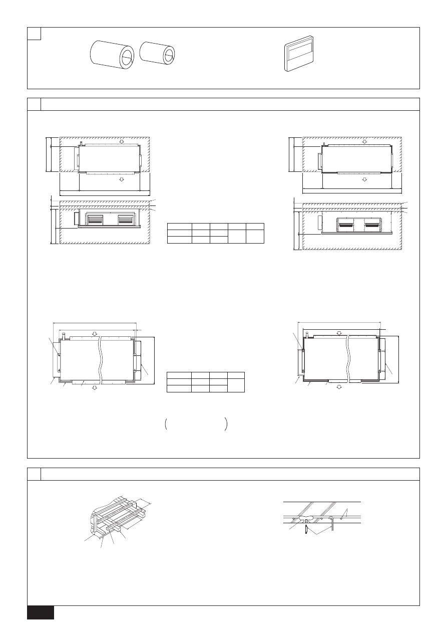
[Fig. 2.0.1]
1
Pipe cover (For field piping connection)
2
3
1
When connecting air inlet
2
When installing the suspension fixtures prior to installation of the
indoor unit without inlet duct
3
When hanging the indoor unit directly without inlet duct
A
Service space
B
Air inlet
C
Air outlet
D
Suspension bolt pitch
E
Top of the unit
F
Suspension bolt holes
PEA-200, 250 : 4-ø12 holes
PEA-400, 500 : 4-ø15 holes
G
Control box
H
Drain pan
I
Main body
[Fig. 3.2.1]
[Fig. 3.2.2]
F
G
H
A
B
D
C
E
E
4
4.1
A
Ceiling board
B
Edge beam
C
Tie beam
D
Square timber for hanging the air conditioner
E
Pitch
F
Insert: 100 to 150 kg (1 piece) (field supply)
G
Hanging bolt (field supply)
PEA-200, 250 : M10
PEA-400, 500 : M12
H
Reinforcement
[Fig. 4.1.1]
[Fig. 4.1.2]
3.2
* In case of PEA-200, 250
* In case of PEA-400, 500
200
530
200
400
730
75
25
C
D
500
1
2
3
A
A
B
C
B
A
200
664
200
400
864
75
25
1095
595
500
1
2
3
A
A
B
C
1800
2400
* In case of PEA-200, 250
* In case of PEA-400, 500
20
B
C
D
D
F
G
H
E
I
A
C
B
199
200
131
20
764
B
C
D
D
F
G
H
E
I
1947
1840
203
320
141
C
634
B
1300
1500
Model
PEA-200
PEA-500
A
1400
1600
C
900
Model
PEA-200
PEA-500
A
1860
2060
B
1260
1460
D
400
2
LCD remote controller
3
G
B
D
F
S
W
I
N
L
E
P
6.2
5
5.1
A
30
B
A
B
A
*1
A
30
B
10
A
A
B
[Fig. 5.1.1]
[Fig. 5.1.2]
[Fig. 5.1.3]
A
Unit body
B
Lifting machine
A
Nut
B
Washer
A
Be sure to attach a U-shaped
washer (4 washers in total).
A
6
A
Refrigerant pipe (liquid pipe)
B
Refrigerant pipe (gas pipe)
C
Drain pipe
[Fig. 5.2.1]
[Fig. 6.2.1]
A
Level check
C
E
100
B
A
D
C
B
A
117
45
100
52
156
117
81
102
C
A
A
B
B
* In case of PEA-200, 250
* In case of PEA-400, 500
7
7.1
[Fig. 7.1.1]
[Fig. 7.1.2]
A
Thermal insulation
B
Pull out insulation
C
Wrap with damp cloth
D
Return to original position
E
Ensure that there is no gap here
F
Wrap with insulating tape
G
Pipe cover (Accessory part)
A
Brazing
B
Gas pipe
C
Liquid pipe
D
Indoor unit
E
Outdoor unit
* Refore to the Outdoor Installation Manual
for connecting to the outdoor unit.
[Fig.7.1.3]
A
A
Remove the cap
* In case of PEA-200, 250
* In case of PEA-400, 500
A
A
G
E
C
F
B
D
A
A
B
E
E
C
A
C
B
D
(No.2)
(No.1)
A
A
B
E
C
D
5.2
C
89
A
144
B
145
D
52
E
42
Model
PEA-200, 250
4
G
B
D
F
S
W
I
N
L
E
P
33
525
4 × 120(=480)
22.5
22
29
1618
12 × 130(=1560)
1125
8 × 130(=1040)
42.5
280
40
188
340
2 × 130(=260)
C
C
A
B
34
K
25
2 × 100(=200)
I
2 × 130(=260)
J
A
B
D
G
C
F
H
250
E
A
B
7
7.2
[Fig.7.2.1]
8
F
A
B
D
C
E
G
G
E
B
C
D
A
12.5
25~100mm
10mm
[Fig.8.0.1]
A
Air inlet
B
Air outlet
C
Access door
D
Ceiling surface
E
Canvas duct
F
Keep duct-work length 850 or more
G
Connect common reference potential wire between duct-work to air conditioner
[Fig.8.0.2]
A
Inlet duct flange
B
Return air temperature sensor
C
Sensor protection plate
D
Sensor fixture
E
Inlet duct
A
B
G
F
D
H
I
J
E
C
A
Insulator
B
Drain pipe R1
C
Drain pan
D
>
= 70 mm
E
>
= 2 × F >
= 70 mm
F
>
= 35 mm
G
Downward slope 20 mm/m or more
H
Drain trap
I
The drain pipe should extend below this level.
J
Open drain
* In case of PEA-200, 250
* In case of PEA-400, 500
12.5
2-
20
A
B
C
D
E
25~100 mm
10 mm
[Fig.8.0.3]
A
Inlet duct flange
B
Outlet duct flange
C
Top of the unit
* In case of PEA-200, 250
* In case of PEA-400, 500
C
1000
B
8 × 130 (=1040)
9 × 130 (=1170)
Model
PEA-200
PEA-250
A
1102
1302
E
330
D
7 × 130 (=910)
F
105
205
G
45
H
31
66
I
35
J
22
K
95
5
G
B
D
F
S
W
I
N
L
E
P
9
S1 S2 S3
S1 S2 S3
G
G
H
H
I
L1 L2 L3 N
S1 S2 S3
S1 S2 S3
S1 S2 S3
S1 S2 S3
L1 L2 L3 N
1
D
2
C
B
A
A
B
C
E
G
H
I
L1 L2 L3 N
L1 L2 L3 N
1
D
2
C
B
A
A
B
C
A
B
C
E
(No.1 Outdoor)
F
F
G
G
I
I
L1 L2 L3 N
E
(No.2 Outdoor)
I
[Fig.9.0.1]
[Fig.9.0.2]
A
Power supply
B
Earth leakage breaker
C
Circuit breaker or local switch
D
LCD remote controller
E
Outdoor unit
F
Indoor unit
G
Power cable wiring
H
Indoor/Outdoor connection wiring
I
Grounding
* In case of PEA-200, 250
* In case of PEA-400, 500
A
B
C
A
B
C
A
For remote controller cables
B
For outdoor unit connection cables
C
For power supply cables
* In case of PEA-200, 250
* In case of PEA-400, 500
PUHZ-200, 250
PEA-200, 250
PUHZ-200, 250
PEA-400, 500
PUHZ-200, 250
(TB4-1) (TB4-2)

6
G
B
D
F
S
W
I
N
L
E
P
30
46
30
30
120
83.5
C
A
B
D
(1)
[Fig.11.1.1]
(2)
(3)
A
Remote controller pro-
file
B
Required clearances
surrounding the re-
mote controller
C
Temperature sensor
D
Installation pitch
C
Wall
D Conduit
E
Lock nut
F Bushing
G
Switch box
H Remote controller cord
I
Seal with putty
F
H
C
D
E
G
I
I
B-1.
B-2.
I
<A> For installation in the switch box:
<B> For direct installation on the wall
select one of the following:
<A>
For installation in the switch box
<B> For direct installation on the wall
C
Switch box for two pieces
D
Remote controller cord
E
Cross-recessed, pan-head screw
G
Seal the remote controller cord service entrance with putty
H
Wood screw
11
11.1
11.2
11.3
[Fig.11.2.1]
[Fig.11.3.1]
[Fig.11.3.2]
AB
TB6
A
B
A
To TB5 on the indoor unit
B
Terminal block TB6 in remote controller
No polarity
10.1
10
[Fig.10.1.1]
A
Outdoor unit
B
Indoor unit
C
Main remote controller
D
Subordinate remote controller
E
Standard (Refrigerant address = 00)
F
Refrigerant address = 01
G
Refrigerant address = 02
H
Refrigerant address = 03
I
Refrigerant address = 14
J
Refrigerant address = 15
1
1
2
2
2
A
A
B
A
B
B
B
F
G
J
E
C
A
D
* In case of PEA-200, 250
* In case of PEA-400, 500
1
1
2
2
B
B
B
C
D
A
No.1
A
No.2
A
No.1
A
No.2
A
No.1
A
E
F
G
H
I
J
No.2
H
D
E
D
C
G
7
G
B
D
K
S
W
N
L
I
E
F
D
R
U
T
R
G
R
P
Contents
1. Safety precautions
s Before installing the unit, make sure you read all the “Safety
precautions”.
s The “Safety precautions” provide very important points re-
garding safety. Make sure you follow them.
Symbols used in the text
Warning:
Describes precautions that should be observed to prevent danger of injury
or death to the user.
Caution:
Describes precautions that should be observed to prevent damage to the
unit.
After installation work has been completed, explain the “Safety Precautions”, use,
and maintenance of the unit to the customer according to the information in the
Operation Manual and perform the test run to ensure normal operation. Both the
Installation Manual and Operation Manual must be given to the user for keeping.
These manuals must be passed on to subsequent users.
Symbols put on the unit
: Indicates an action that must be avoided.
: Indicates that important instructions must be followed.
: Indicates a part which must be grounded.
: Beware of electric shock. (This symbol is displayed on the main unit label.)
<Color: yellow>
Warning:
Carefully read the labels affixed to the main unit.
Warning:
•
Ask the dealer or an authorized technician to install the air conditioner.
- Improper installation by the user may result in water leakage, electric shock,
or fire.
•
Install the unit at a place that can withstand its weight.
- Inadequate strength may cause the unit to fall down, resulting in injuries.
•
Use the specified cables for wiring. Make the connections securely so
that the outside force of the cable is not applied to the terminals.
- Inadequate connection and fastening may generate heat and cause a fire.
•
Prepare for strong winds and earthquakes and install the unit at the speci-
fied place.
- Improper installation may cause the unit to topple and result in injury.
•
Always use an filter and other accessories specified by Mitsubishi Elec-
tric.
- Ask an authorized technician to install the accessories. Improper installation
by the user may result in water leakage, electric shock, or fire.
•
Never repair the unit. If the air conditioner must be repaired, consult the
dealer.
- If the unit is repaired improperly, water leakage, electric shock, or fire may
result.
•
Do not touch the heat exchanger fins.
- Improper handling may result in injury.
•
When handling this product, always wear protective equipment.
EG: Gloves, full arm protection namely boiler suit, and safety glasses.
- Improper handling may result in injury.
•
If refrigerant gas leaks during installation work, ventilate the room.
- If the refrigerant gas comes into contact with a flame, poisonous gases will
be released.
•
Install the air conditioner according to this Installation Manual.
- If the unit is installed improperly, water leakage, electric shock, or fire may
result.
•
Have all electric work done by a licensed electrician according to “local
regulations” and the instructions given in this manual.
- If the power source capacity is inadequate or electric work is performed im-
properly, electric shock and fire may result.
•
Securely install the outdoor unit terminal cover (panel).
- If the terminal cover (panel) is not installed properly, dust or water may enter
the outdoor unit and fire or electric shock may result.
•
When installing or relocating the unit, make sure that no substance other
than the specified refrigerant (R410A) enters the refrigerant circuit.
- Any presence of foreign substance such as air can cause abnormal pres-
sure rise or explosion.
•
If the air conditioner is installed in a small room, measures must be taken
to prevent the refrigerant concentration in the room from exceeding the
safety limit in the event of the refrigerant leakage.
- Consult the dealer regarding the appropriate measures to prevent the safety
limit from being exceeded. Should the refrigerant leak and cause the safety
limit to be exceeded, hazards due to lack of oxygen in the room could result.
•
When moving and reinstalling the air conditioner, consult the dealer or
an authorized technician.
- If the air conditioner is installed improperly, water leakage, electric shock, or
fire may result.
•
After completing installation work, make sure that refrigerant gas is not
leaking.
- If the refrigerant gas leaks and is exposed to a fan heater, stove, oven, or
other heat source, it may generate noxious gases.
•
Do not reconstruct or change the settings of the protection devices.
- If the pressure switch, thermal switch, or other protection device is shorted
and operated forcibly, or parts other than those specified by Mitsubishi Elec-
tric are used, fire or explosion may result.
•
To dispose of this product, consult your dealer.
•
The installer and system specialist shall secure safety against leakage
according to local regulation or standards.
- Following standards may be applicable if local regulation are not available.
•
Pay a special attention to the place, such as a basement, etc. where re-
frigeration gas can stay, since refrigeration is heavier than the air.
1.1. Before installation
Caution:
•
Do not install the unit where combustible gas may leak.
- If the gas leaks and accumulates around the unit, an explosion may result.
•
Do not use the air conditioner where food, pets, plants, precision instru-
ments, or artwork are kept.
- The quality of the food, etc. may deteriorate.
1. Safety precautions ...................................................................................... 7
1.1. Before installation ...................................................................... 7
1.2. Before installation (relocation) ................................................... 8
1.3. Before electrical work ................................................................ 8
1.4. Before starting the test run ........................................................ 8
2. Indoor unit accessories ............................................................................... 8
3. Selecting an installation site ....................................................................... 8
3.1. Install the indoor unit on a ceiling strong enough to
sustain its weight ....................................................................... 8
3.2. Securing installation and service space .................................... 8
3.3. Combining indoor units with outdoor units ................................ 9
4. Fixing hanging bolts .................................................................................... 9
4.1. Fixing hanging bolts .................................................................. 9
5. Installing the unit ......................................................................................... 9
5.1. Hanging the unit body ............................................................... 9
5.2. Confirming the unit’s position and fixing hanging bolts ............. 9
6. Refrigerant pipe and drain pipe specifications .......................................... 10
6.1. Refrigerant pipe and drain pipe specifications ........................ 10
6.2. Refrigerant pipe, drain pipe and filling port ............................. 10
7. Connecting refrigerant pipes and drain pipes ........................................... 10
7.1. Refrigerant piping work ........................................................... 10
7.2. Drain piping work ..................................................................... 10
8. Duct work .................................................................................................. 11
9. Electrical wiring ......................................................................................... 11
10. System control .......................................................................................... 12
10.1 Grouping by using LCD remote controller ............................... 12
10.2 Examples of refrigerant system address setting ..................... 12
11. LCD remote controller ............................................................................... 13
11.1. Installing procedures ............................................................... 13
11.2. Connecting procedures ........................................................... 13
11.3. Fitting the upper case .............................................................. 13
11.4. Function selection ................................................................... 13
12. Test run ...................................................................................................... 17
12.1. Before test run ......................................................................... 17
12.2. Test run procedures ................................................................. 17
12.3. Self-check ................................................................................ 18
12.4. Remote controller check .......................................................... 18
13. Troubleshooting ......................................................................................... 19
13.1. How to handle problems with the test run ............................... 19
13.2. The following occurrences are not problems or errors ............. 20
8
G
B
D
K
S
W
N
L
I
E
F
D
R
U
T
R
G
R
P
2. Indoor unit accessories
The unit is provided with the following accessories:
[Fig. 2.0.1]
(P.2)
•
Select a site with sturdy fixed surface sufficiently durable against the weight of
unit.
•
Before installing unit, the routing to carry in unit to the installation site should
be determined.
•
Select a site where the unit is not affected by entering air.
•
Select a site where the flow of supply and return air is not blocked.
•
Select a site where refrigerant piping can easily be led to the outside.
•
Select a site which allows the supply air to be distributed fully in room.
•
Do not install unit at a site with oil splashing or steam in much quantity.
•
Do not install unit at a site where combustible gas may generate, flow in, stag-
nate or leak.
•
Do not install unit at a site where equipment generating high frequency waves
(a high frequency wave welder for example) is provided.
•
Do not install unit at a site where fire detecter is located at the supply air side.
(Fire detector may operate erroneously due to the heated air supplied during
heating operation.)
•
When special chemical product may scatter around such as site chemical plants
and hospitals, full investigation is required before installing unit. (The plastic
components may be damaged depending on the chemical product applied.)
3. Selecting an installation site
•
If the indoor unit is run in a place subject to high temperatures and humidity
(the dew-point temperature is 26 °C or more inside the ceiling) for a long time,
dew condensation may occur on the indoor unit. When operated under such
condition, add more insulating material (10-20 mm) on the surface of the in-
door unit to prevent dew condensation.
3.1. Install the indoor unit on a ceiling strong
enough to sustain its weight
Warning:
The unit must be securely installed on a structure that can sustain its weight.
If the unit is mounted on an unstable structure, it may fall down causing
injuries.
3.2. Securing installation and service space
•
Select the optimum direction of supply airflow according to the configuration of
the room and the installation position.
•
As the piping and wiring are connected at the bottom and side surfaces, and
the maintenance is made at the same surfaces, allow a proper space properly.
For the efficient suspension work and safety, provide a space as much as
possible.
•
Do not use the air conditioner in special environments.
- Oil, steam, sulfuric smoke, etc. can significantly reduce the performance of
the air conditioner or damage its parts.
•
When installing the unit in a hospital, communication station, or similar
place, provide sufficient protection against noise.
- The inverter equipment, private power generator, high-frequency medical
equipment, or radio communication equipment may cause the air conditioner
to operate erroneously, or fail to operate. On the other hand, the air condi-
tioner may affect such equipment by creating noise that disturbs medical
treatment or image broadcasting.
•
Do not install the unit on a structure that may cause leakage.
- When the room humidity exceeds 80 % or when the drain pipe is clogged,
condensation may drip from the indoor unit. Perform collective drainage work
together with the outdoor unit, as required.
1.2. Before installation (relocation)
•
Do not wash the air conditioner units.
- Washing them may cause an electric shock.
•
Be careful that the installation base is not damaged by long use.
- If the damage is left uncorrected, the unit may fall and cause personal injury
or property damage.
•
Install the drain piping according to this Installation Manual to ensure
proper drainage. Wrap thermal insulation around the pipes to prevent
condensation.
- Improper drain piping may cause water leakage and damage to furniture
and other possessions.
•
Be very careful about product transportation.
- Only one person should not carry the product if it weighs more than 20 kg.
- Some products use PP bands for packaging. Do not use any PP bands for a
means of transportation. It is dangerous.
- Do not touch the heat exchanger fins. Doing so may cut your fingers.
•
Safely dispose of the packing materials.
- Packing materials, such as nails and other metal or wooden parts, may cause
stabs or other injuries.
- Tear apart and throw away plastic packaging bags so that children will not
play with them. If children play with a plastic bag which was not torn apart,
they face the risk of suffocation.
1.3. Before electrical work
Caution:
•
Ground the unit.
- Do not connect the ground wire to gas or water pipes, lightning rods, or
telephone ground lines. Improper grounding may result in electric shock.
•
Install the power cable so that tension is not applied to the cable.
- Tension may cause the cable to break and generate heat and cause a fire.
•
Install an earth leakage circuit breaker, as required.
- If an leak circuit breaker is not installed, electric shock may result.
•
Use power line cables of sufficient current carrying capacity and rating.
- Cables that are too small may leak, generate heat, and cause a fire.
•
Use only a circuit breaker and fuse of the specified capacity.
- A fuse or circuit breaker of a larger capacity or a steel or copper wire may
result in a general unit failure or fire.
1.4. Before starting the test run
Caution:
•
Turn on the power at least 12 hours before starting operation.
- Starting operation immediately after turning on the main power switch can
result in severe damage to internal parts. Keep the power switch turned on
during the operational season.
•
Do not touch the switches with wet fingers.
- Touching a switch with wet fingers can cause electric shock.
•
Do not touch the refrigerant pipes during and immediately after opera-
tion.
- During and immediately after operation, the refrigerant pipes are may be hot
and may be cold, depending on the condition of the refrigerant flowing through
the refrigerant piping, compressor, and other refrigerant cycle parts. Your
hands may suffer burns or frostbite if you touch the refrigerant pipes.
•
Do not operate the air conditioner with the panels and guards removed.
- Rotating, hot, or high-voltage parts can cause injuries.
•
Do not turn off the power immediately after stopping operation.
- Always wait at least five minutes before turning off the power. Otherwise,
water leakage and trouble may occur.
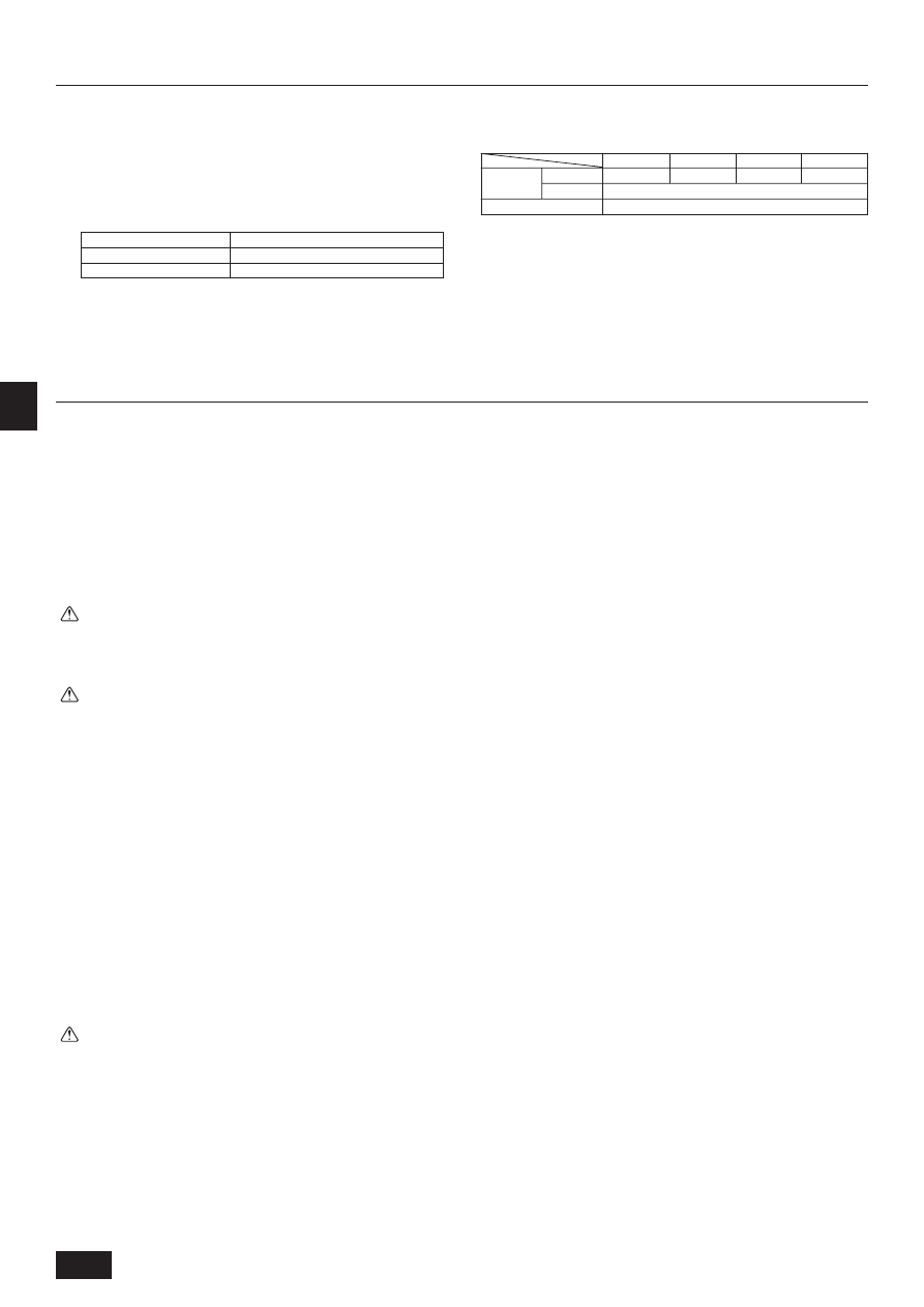
Accessory name
Pipe cover (For field piping connection)
• Small diameter
• Large diameter
Model (Qty*)
PEA-200, 250
PEA-400, 500
1
2
1
2
1
2
1
LCD remote controller
9
G
B
D
K
S
W
N
L
I
E
F
D
R
U
T
R
G
R
P
Service space
[Fig. 3.2.1]
(P.2)
1
When connecting air inlet
2
When installing the suspension fixtures prior to installation of the indoor unit with-
out inlet duct
3
When hanging the indoor unit directly without inlet duct
A
Service space
B
Air inlet
C
Air outlet
4.1. Fixing hanging bolts
Hanging structure
•
Ceiling: The ceiling structure varies from building to one another. For detailed
information, consult your construction company.
1 Reinforcing the ceiling with additional members (edge beam, etc.) must be
required to keep the ceiling at level and to prevent the ceiling from vibrations.
2 Cut and remove the ceiling members.
3 Reinforce the ceiling members, and add other members for fixing the ceiling
boards.
For wooden construction
•
Use the tie beam (for one story building) or second-floor beam (for two story
building) as strength members.
•
To hang the air-conditioner, use a hard square timber of more than 6 cm if the
distance between beams is less than 90 cm and a hard square timber of more
than 9 cm if the distance between beams is less than 180 cm.
4. Fixing hanging bolts
[Fig. 4.1.1]
(P.2)
A
Ceiling board
B
Edge beam
C
Tie beam
D
Square timber for hanging the air conditioner
E
Pitch
For reinforced concrete construction
•
As shown in the figure below, fix the hanging bolts, or use square timbers to fix
the hanging bolts.
[Fig. 4.1.2]
(P.2)
F
Insert: 100 to 150 kg (1 piece) (field supply)
G
Hanging bolt (field supply)
PEA-200, 250 : M10
PEA-400, 500 : M12
H
Reinforcement
Product Weight (kg)
PEA-200
70 kg
PEA-250
77 kg
PEA-400
130 kg
PEA-500
133 kg
5. Installing the unit
5.1. Hanging the unit body
s Bring the indoor unit to an installation site as it is packed.
s To hang the indoor unit, use a lifting machine to lift and pass through the
hanging bolts.
s Install the indoor unit before ceiling work.
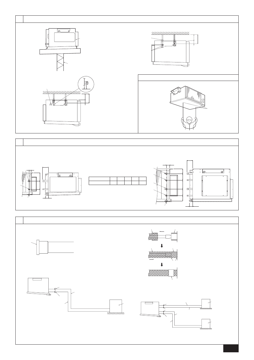
[Fig. 5.1.1]
(P.3)
A
Unit body
B
Lifting machine
* Two installation methods are available
<When hanging the indoor unit directly>
1. Attach a washer and nut(s) to each suspension bolt. (The washers and nuts
are to be supplied locally.)
2. Fit the indoor unit to each suspension bolt.
3. Make sure that the unit is positioned level, then tighten each nut.
[Fig. 5.1.2]
(P.3)
A
Nut
B
Washer
A
B
When using inlet duct
100 or more
130 or more
When not using inlet duct
0 or more
30 or more
Nut (*1) is not required if distance A is 0.
<When installing the suspension fixture prior to installation of the indoor unit>
1. Loosen each suspension fixture bolt slightly, and remove the fixture and U-
shaped washers.
2. Adjust each suspension fixture bolt.
3. Attach a washer, nut and suspension fixture to each suspension bolt. (The
washers and nuts are to be supplied locally.)
4. Hook the indoor unit to the suspension fixtures.
5. Make sure that the unit is positioned level, then tighten each nut.
[Fig. 5.1.3]
(P.3)
A
Be sure to attach a U-shaped washer (4 washers in total).
A
B
When using inlet duct
100 or more
130 or more
When not using inlet duct
25 or more
55 or more
5.2. Confirming the unit’s position and fix-
ing hanging bolts
[Fig. 5.2.1]
(P.3)
A
Level check
s Use the gage supplied with the panel to confirm that the unit body and
hanging bolts are positioned in place. If they are not positioned in place,
it may result in dew drops due to wind leak. Be sure to check the positional
relationship.
s Use a level to check that the surface indicated by A is at level. Ensure
that the hanging bolt nuts are tightened to fix the hanging bolts.
s To ensure that drain is discharged, be sure to hang the unit at level using
a level.
Caution:
Be sure to install the unit body at level.
Suspension bolt pitch
[Fig. 3.2.2]
(P.2)
D
Suspension bolt pitch
E
Top of the unit
F
Suspension bolt holes
PEA-200, 250 : 4-ø12 holes
PEA-400, 500 : 4-ø15 holes
G
Control box
H
Drain pan
I
Main body
3.3. Combining indoor units with outdoor
units
For combining indoor units with outdoor units, refer to the outdoor unit installation
manual.
10
G
B
D
K
S
W
N
L
I
E
F
D
R
U
T
R
G
R
P
6.1. Refrigerant pipe and drain pipe specifi-
cations
6.2. Refrigerant pipe, drain pipe and filling
port
[Fig. 6.2.1]
(P.3)
A
Refrigerant pipe (liquid pipe)
B
Refrigerant pipe (gas pipe)
C
Drain pipe
7.1. Refrigerant piping work
This piping work must be done in accordance with the installation manuals for
outdoor unit.
•
The method of pipe connection is brazing connection.
Cautions on refrigerant piping
s Be sure to use non-oxidative brazing for brazing to ensure that no for-
eign matter or moisture enter into the pipe.
s Provide a metal brace to support the refrigerant pipe so that no load is
imparted to the indoor unit end pipe. This metal brace should be pro-
vided 50 cm away from the indoor unit’s brazing connection.
Warning:
When installing or relocating the unit, make sure that no substance other
than the specified refrigerant (R410A) enters the refrigerant circuit.
- Any presence of foreign substance such as air can cause abnormal pressure
rise or explosion.
Caution:
•
Install the refrigerant piping for the indoor unit in accordance with the
following.
1. Remove the cap.
[Fig. 7.1.1]
(P.3)
A
Remove the cap
2. Pull out the thermal insulation on the site refrigerant piping, braze the unit
piping, and replace the insulation in its original position.
Wrap the piping with insulating tape.
[Fig. 7.1.2]
(P.3)
A
Thermal insulation
B
Pull out insulation
C
Wrap with damp cloth
D
Return to original position
E
Ensure that there is no gap here
F
Wrap with insulating tape
G
Pipe cover (Accessory part)
Note:
•
Pay strict attention when wrapping the copper piping since wrapping the
piping may cause condensation instead of preventing it.
*
Before brazing the refrigerant piping, always wrap the piping on the main
body, and the thermal insulation piping, with damp cloths to prevent heat
shrinkage and burning the thermal insulation tubing.
Take care to ensure
that the flame does not come into contact with the main body itself.
Caution:
•
Use refrigerant piping made of C1220 (CU-DHP) phosphorus deoxidized
copper as specified in the JIS H3300 “Copper and copper alloy seamless
pipes and tubes”. In addition, be sure that the inner and outer surfaces of
the pipes are clean and free of hazardous sulphur, oxides, dust/dirt, shav-
ing particles, oils, moisture, or any other contaminant.
•
Never use existing refrigerant piping.
- The large amount of chlorine in conventional refrigerant and refrigerator oil
in the existing piping will cause the new refrigerant to deteriorate.
•
Store the piping to be used during installation indoors and keep both
ends of the piping sealed until just before brazing.
- If dust, dirt, or water gets into the refrigerant cycle, the oil will deteriorate and
the compressor may fail.
•
Do not use a leak detection additive.
To avoid dew drops, provide sufficient antisweating and insulating work to the re-
frigerant and drain pipes.
When using commercially available refrigerant pipes, be sure to wind commer-
cially available insulating material (with a heat-resisting temperature of more than
100 °C and thickness given below) onto both liquid and gas pipes.
Be also sure to wind commercially available insulating material (with a form
polyethylene’s specific gravity of 0.03 and thickness given below) onto all pipes
which pass through rooms.
1 Select the thickness of insulating material by pipe size.
Pipe size
Insulating material’s thickness
6.4 mm to 25.4 mm
More than 10 mm
28.6 mm to 38.1 mm
More than 15 mm
2 If the unit is used on the highest story of a building and under conditions of
high temperature and humidity, it is necessary to use pipe size and insulating
material’s thickness more than those given in the table above.
3 If there are customer’s specifications, simply follow them.
6. Refrigerant pipe and drain pipe specifications
7. Connecting refrigerant pipes and drain pipes
Additional refrigerant charge
•
Take care not to allow dirt or cutting chips to enter the refrigerant pipes.
•
The refrigerant pipes must be kept warm, so take particular care to insulate
between refrigerant pipes and the gas pipe located inside the indoor unit, since
the gas pipe causes condensation during cooling operation.
•
When connecting the refrigerant pipes, make sure that the stop valve of the
outdoor unit is fully closed (as it was when shipped from the factory). After
connecting all the refrigerant pipes between the indoor and outdoor units, purge
air from the stop valve service port of the outdoor unit and service port of each
connecting pipe. Check that there is no air leakage from any pipe connection,
then fully open the stop valve of the outdoor unit. This will connect the refriger-
ant circuit between the indoor and outdoor units.
•
The refrigerant pipes must be as short as possible.
•
The indoor and outdoor units must be connected with the refrigerant pipes.
[Fig. 7.1.3]
(P.3)
A
Brazing
B
Gas pipe
C
Liquid pipe
D
Indoor unit
E
Outdoor unit
7.2. Drain piping work
[Fig. 7.2.1]
(P.4)
A
Insulator
B
Drain pipe R1
C
Drain pan
D
>
= 70 mm
E
>
= 2 × F >
= 70 mm
F
>
= 35 mm
G
Downward slope 20 mm/m or more H
Drain trap
I
The drain pipe should extend below this level.
J
Open drain
Refrigerant
pipe
Drain pipe
Liquid pipe
Gas pipe
R1 (Male screw)
Model
Item
PEA-200
ø9.52
PEA-250
ø12.7
PEA-400
ø9.52
PEA-500
ø12.7
ø25.4
11
G
B
D
K
S
W
N
L
I
E
F
D
R
U
T
R
G
R
P
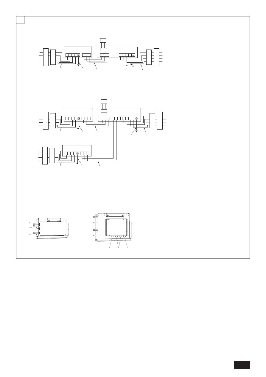
9. Electrical wiring
Precautions on electrical wiring
Warning:
Electrical work should be done by qualified electrical engineers in accord-
ance with “local regulations” and supplied installation manuals. Special cir-
cuits should also be used. If the power circuit lacks capacity or has an instal-
lation failure, it may cause a risk of electric shock or fire.
1. Be sure to take power from the special branch circuit.
2. Be sure to install an earth leakage breaker to the power.
3. Install the unit to prevent that any of the control circuit cables (remote control-
ler, transmission cables) is brought in direct contact with the power cable out-
side the unit.
4. Ensure that there is no slack on all wire connections.
5. Some cables (power, remote controller, transmission cables) above the ceiling
may be bitten by mouses. Use as many metal pipes as possible to insert the
cables into them for protection.
6. Never connect the power cable to leads for the transmission cables. Otherwise
the cables would be broken.
7. Be sure to connect control cables to the indoor unit, remote controller, and the
outdoor unit.
8. Put the unit to the ground on the outdoor unit side.
9. Be sure to connect between the control cable terminal block of the outdoor unit
and that of the indoor unit. (Cables have polarity, so make sure that they are
connected according to the terminal numbers.)
10. Fix power source wiring to control box by using buffer bushing for tensible force
(PG connection or the like). Connect control wiring to control terminal bed
through the knockout hole of control box using ordinary bushing.
11. Do not connect the unit in the reverse phase sequence.
If connected in the reverse phase sequence, the indoor unit will not be able to
provide sufficient cooling air. (PEA-200, 250, 400, 500)
8. Duct work
•
In connecting duct, insert canvas duct between unit and duct.
•
Use incombustible material for duct parts.
•
Provide full insulation to inlet duct flange, outlet duct flange and outlet duct to
prevent condensation.
•
Be sure to apply the air filter near the air inlet grille.
•
Before connecting an inlet duct, remove the air filter, then install that filter in the
inlet grille.
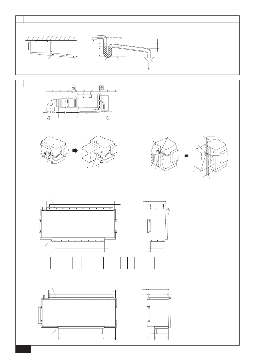
[Fig. 8.0.1]
(P.4)
A
Air inlet
B
Air outlet
C
Access door
D
Ceiling surface
E
Canvas duct
F
Keep duct-work length 850 or more
G
Connect common reference potential wire between duct-work to air conditioner
Caution:
•
Outlet duct is 850 mm or more necessary to construct.
•
To connect the air conditioner main body and the duct for potential equali-
zation.
•
Return air temperature sensor when an inlet duct is installed.
A return air temperature sensor is installed on the inlet duct flange. Before
connecting an inlet duct, this sensor must be removed and installed in the
specified position.
[Fig. 8.0.2]
(P.4)
A
Inlet duct flange
B
Return air temperature sensor
C
Sensor protection plate
D
Sensor fixture
E
Inlet duct
1
Pull out the sensor, and remove the sensor fixture and protection plate. (The
protection plate must be discarded.)
2
Connect the inlet duct.
3
Drill a sensor hole (ø12.5 dia.) on the side on the duct.
4
Assemble the sensor and fixture.
•
When pulling out the sensor, do not pull it by the lead wire. Doing so may result
in wire breakage.
•
Before connecting the inlet duct, make sure that the sensor, its fixture and
protection plate are removed.
•
The sensor removed in step 1 must be re-installed in the position specified in
the drawing. Installation of the sensor in an incorrect position may result in
malfunction.
Mount holes for outlet duct flange and inlet duct.
[Fig. 8.0.3]
(P.4)
A
Inlet duct flange
B
Outlet duct flange
C
Top of the unit
In case of A-control wiring there is high voltage potential on the S3 terminal
caused by electrical circuit design that has no electrical insulation between
power line and communication signal line. Therefore, please turn off the main
power supply when servicing. And do not touch the S1, S2, S3 terminals
when the power is energized. If isolator should be used between indoor unit
and outdoor unit, please use 3-potes type.
Caution:
Be sure to put the unit to the ground on the outdoor unit side. Do not con-
nect the earth cable to any gas pipe, water pipe, lightening rod, or telephone
earth cable. Incomplete grounding may cause a risk of electric shock.
[Fig. 9.0.1]
(P.5)
A
Power supply
B
Earth leakage breaker
C
Circuit breaker or local switch
D
LCD remote controller
E
Outdoor unit
F
Indoor unit
G
Power cable wiring
H
Indoor/Outdoor connection wiring
I
Grounding
Caution:
For PEA-400, 500, make sure that refrigerant pipes and wirings be connected
from Outdoor unit No.1 to Indoor unit No.1 and Outdoor unit No.2 to Indoor
unit No.2 respectively.
Wiring from Outdoor unit No.1 must be connected to terminal bed TB4-1, and
wiring from Outdoor unit No.2 must be connected to TB4-2 in Indoor unit
control box.
Any mistakes on those connections may cause an abnormal refrigerant pipe
temperature and etc.
1. Ensure that a drain trap is installed. If this is neglected, condensation may
occur inside the indoor unit leading to water leakage/equipment breakdown,
etc.
2. Ensure that the drain piping is downward (pitch of more than 20 mm/m) to the
outdoor (discharge) side.
3. Ensure that any cross-wise drain piping is less than 20 m (excluding the differ-
ence of elevation). If the drain piping is long, provide metal braces to prevent it
from waving. Never provide any air vent pipe. Otherwise drain may be ejected.
4. Use a hard vinyl chloride pipe VP-25 (with an external diameter of 32 mm) for
drain piping.
5. Ensure that collected pipes are 10 cm lower than the unit body’s drain port.
6. Put the end of the drain piping in a position where no odor is generated.
7. Do not put the end of the drain piping in any drain where ionic gases are
generated.
12
G
B
D
K
S
W
N
L
I
E
F
D
R
U
T
R
G
R
P
10.1 Grouping by using LCD remote controller
Combination of indoor/outdoor unit can be controlled up to a maximum of 16 refrig-
erant systems.
[Fig. 10.1.1]
(P.6)
A
Outdoor unit
B
Indoor unit
C
Main remote controller
D
Subordinate remote controller
E
Standard (Refrigerant address = 00)
F
Refrigerant address = 01
G
Refrigerant address = 02
H
Refrigerant address = 03
I
Refrigerant address = 14
J
Refrigerant address = 15
* Set the refrigerant address using the DIP switch of the outdoor unit.
*
Refer to the outdoor unit installation manual for setting method of SW1
DIP switch.
1
Wiring from the Remote Control
This wire is connected to TB5 (terminal board for remote controller) of the indoor
unit (non-polar).
2
When a Different Refrigerant System Grouping is Used
Up to 16 refrigerant systems can be controlled as one group using the LCD remote
controller.
Notes:
1. In single refrigerant system, there is no need of wiring 2.
2. LCD remote controller can be installed up to a maximum of 2 units for
one group.
10. System control
Caution:
Do not use anything other than the correct capacity breaker and fuse. Using
fuse, wire or copper wire with too large capacity may cause a risk of mal-
function or fire.
Location of cable holes
[Fig. 9.0.2]
(P.5)
A
For remote controller cables
B
For outdoor unit connection cables
C
For power supply cables
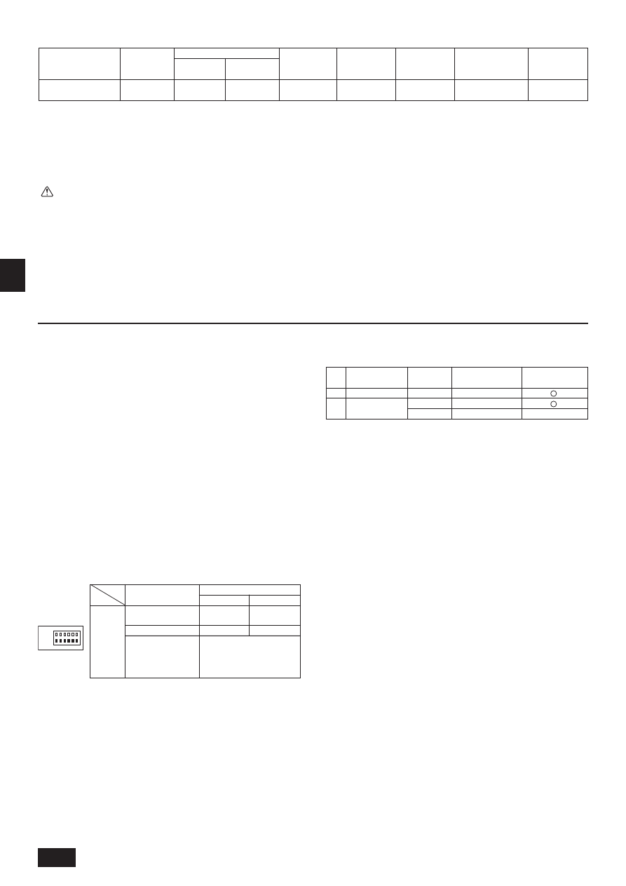
ON
1 2 3 4 5 6
OFF
SW1
Function table
<SW1>
Function
1 Compulsory de-
frosting
2 Error history clear
3
4
5
6
SW1
function
settings
Operation according to switch setting
ON
OFF
Start
Normal
Clear
Normal
Settings for outdoor unit ad-
dresses 0 to 15
Refrigerant sys-
tem address set-
ting
Ex.
1
2
Indoor unit
PEA-200, 250
PEA-400, 500
Outdoor unit
–
No.1
No.2
Outdoor unit refrigerant
system address
00
00
01~15
Remote controller
power supply unit
✕
10.2 Examples of refrigerant system address
setting
* Set the refrigerant system address of one outdoor unit to 00 for the power supply
to the remote controller.
(The refrigerant system address is set to 00 when shipped from the factory.)
Do not duplicate the refrigerant system address settings within the same system.
[Wiring example]
(For metal piping)
Notes:
*1: Connect an earth leakage breaker to the power supply.
*2: Use earth leakage breakers designed exclusively for ground fault protection only in combination with a local switch or a circuit breaker.
*3: The overcurrent protector using a Class-B fuse is shown.
*4: Power supply cords shall not be lighter than polychloroprene sheathed flexible cord. (Design 245 IEC 53 or 227 IEC 53)
*5: Indoor unit/outdoor unit connecting cords shall not be lighter than polychloroprene sheathed flexible cord (Design 245 IEC 57).
*6: A switch with at least 3 mm contact separation in each pole shall be provided by the Air conditioner installation.
*7: The connection wiring between the outdoor and indoor units can be extended up to a maximum of 50 m.
Switch
capacity <A>
16
Circuit breaker
15
Earth leakage
breaker *1, *2
15 A 30 mA
0.1s. or less
PEA-200, 250, 400, 500
Overcurrent
protector *3 <A>
16
Indoor and outdoor
connection wiring *5
1.5 mm
2
or more
Remote controller
wiring
0.3 - 1.25 mm
2
(max. DC 12V)
Local switch
Power cable *4
1.5 mm
2
or more
Earth cable
1.5 mm
2
or more

13
G
B
D
K
S
W
N
L
I
E
F
D
R
U
T
R
G
R
P
11. LCD remote controller
11.1. Installing procedures
(1) Select an installing position for the remote controller (switch box).
Be sure to observe the following precautions.
[Fig.11.1.1]
(P.6)
A
Remote controller profile
B
Required clearances surrounding the remote controller
C
Temperature sensor
D
Installation pitch
1
The temperature sensors are located on both remote controller and indoor
unit. To use the temperature sensor on the remote controller, mainly use the
remote controller for temperature setting or room temperature detection. In-
stall the remote controller in such an area that can detect average room tem-
peratures, free of direct sunlight, airflow from the air conditioner, and other
such heating source.
2
In either case when the remote controller is installed in the switch box or on the
wall, provide the clearances indicated in the diagram.
Note:
Check that there is no electric wire left close to the remote controller sensor.
If any electric wire is near the sensor, the remote controller may fail to detect
a correct room temperature.
3
Procure the following parts locally:
Switch box for two pieces
Thin copper conduit tube
Lock nuts and bushings
(2) Seal the service entrance for the remote controller cord with putty to
prevent possible invasion of dew drops, water, cockroaches or worms.
<A> For installation in the switch box:
•
When the remote controller is installed in the switch box, seal the junction
between the switch box and the conduit tube with putty.
<B> For direct installation on the wall select one of the following:
B-1. To lead the remote controller cord from the back of the controller:
•
Prepare a hole through the wall to pass the remote controller cord (in order to
run the remote controller cord from the back), then seal the hole with putty.
B-2. To run the remote controller cord through the upper portion:
•
Run the remote controller cord through the cut-out upper case, then seal the
cut-out notch with putty similarly as above.
[Fig. 11.1.1]
(P.6)
C
Wall
D
Conduit
E
Lock nut
F
Bushing
G
Switch box
H
Remote controller cord
I
Seal with putty
(3) Install the lower case in the switch box or on the wall.
[Fig. 11.1.1]
(P.6)
<A> For installation in the switch box
C
Switch box for two pieces
D
Remote controller cord
E
Cross-recessed, pan-head screw
G
Seal the remote controller cord service entrance with putty
<B> For direct installation on the wall
H
Wood screw
Caution:
Do not over-tighten the screws to possible deformed or broken lower case.
Note:
•
Select a flat place for installation.
•
Be sure to use two or more locations for securing of the remote control-
ler in the switch box or on the wall.
11.2. Connecting procedures
•
The remote controller cord can be extended up to a maximum of 200 m. Use
electric wires or (two-core) cables of 0.3 mm
2
to 1.25 mm
2
for making connec-
tion of remote controller. Do not use multi-conductor cables to prevent possi-
ble malfunction of the unit.
[Fig. 11.2.1]
(P.6)
(1) Connect the remote controller cord to the terminal block at lower case.
A
To TB5 on the indoor unit
B
Terminal block TB6 in remote controller
No polarity
Caution:
•
Do not use crimp-style terminals for connection to the remote controller
terminal block to eliminate contact with the boards and resultant trouble.
•
Prevent remote cord chips from getting into the remote controller. Elec-
tric shock or malfunction may result.
11.3. Fitting the upper case
[Fig. 11.3.1]
(P.6)
(1) To remove the upper case, put a slotted screwdriver tip in the latches as
shown in the diagram then move the screwdriver in the direction of ar-
row.
(2) To install the upper case, put the upper latches (at two locations) first,
then fit the upper case into the lower case as illustrated.
[Fig. 11.3.2]
(P.6)
Note:
Wiring hole for installing directly on the wall (or open wiring)
•
Cut off the shaded area from the upper case using a knife, nippers, etc.
•
Take out the remote control cord connected to the terminal block via this
portion.
Caution:
•
Do not move the screwdriver while inserting the tip far into the latches to
prevent broken latches.
•
Be sure to put the upper case securely in the latches by pressing it until
a snap sounds. Loosely inserted, the upper case may fall down.
Note:
The operating section is covered with a protective sheet. Before using the
unit, remember to remove the protective sheet.
11.4. Function selection
<Wired remote controller type>
(1) Function selection of remote controller
The setting of the following remote controller functions can be changed using the remote controller function selection mode. Change the setting when needed.
Item 1
1. Change Language
(“CHANGE LANGUAGE”)
2. Function limit
(“FUNCTION
SELECTION”)
3. Mode selection
(“MODE SELECTION”)
4. Display change
(“DISP MODE SETTING”)
Item 3 (Setting content)
• Display in multiple languages is possible.
• Setting the range of operation limit (operation lock)
• Setting the use or non-use of “automatic” operation mode
• Setting the temperature adjustable range (maximum, minimum)
• Setting the use or non-use of the automatic filter elevation panel up/down op-
eration mode
• Setting the use or non-use of the fixed airflow direction mode
• Selecting main or sub remote controller
* When two remote controllers are connected to one group, one controller must be set to sub.
• Setting the use or non-use of clock function
• Setting the timer type
• Contact number display in case of error
• Setting the telephone number
• Setting the temperature unit (°C or °F) to display
• Setting the use or non-use of the display of indoor (suction) air temperature
• Setting the use or non-use of the display of “Cooling” or “Heating” display during
operation with automatic mode
Item 2
Language setting to display
(1) Operation function limit setting (operation lock) (“LOCKING FUNCTION”)
(2) Use of automatic mode setting (“SELECT AUTO MODE”)
(3) Temperature range limit setting (“LIMIT TEMP FUNCTION”)
*(4) Use of automatic filter elevation panel up/down operation mode
setting
*(5) Use of fixed airflow direction mode setting
(1) Remote controller main/sub setting (“CONTROLLER MAIN/SUB”)
(2) Use of clock setting (“CLOCK”)
(3) Timer function setting (“WEEKLY TIMER”)
(4) Contact number setting for error situation (“CALL.”)
(1) Temperature display °C/°F setting (“TEMP MODE °C/°F”)
(2) Suction air temperature display setting (“ROOM TEMP DISP SELECT”)
(3) Automatic cooling/heating display setting (“AUTO MODE DISP C/H”)
* This model is not equipped with this function. The setting is invalid.
14
G
B
D
K
S
W
N
L
I
E
F
D
R
U
T
R
G
R
P
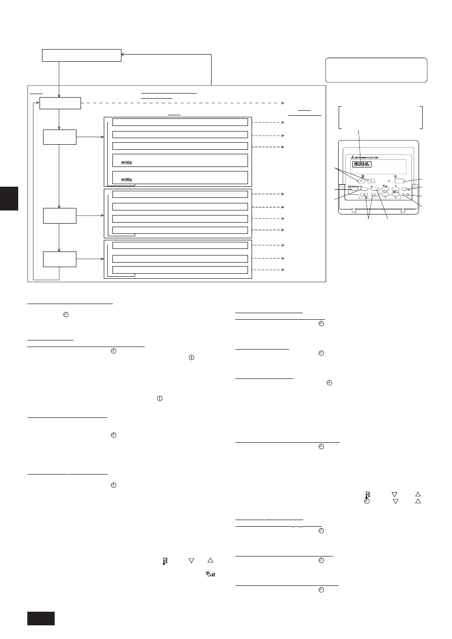
[Function selection flowchart]
[1] Stop the air conditioner to start remote controller function selection mode. !
!
!
!
!
[2] Select from item1. !
!
!
!
!
[3] Select from item2. !
!
!
!
!
[4] Make the setting. (Details
are specified in item3) !
!
!
!
!
[5] Setting completed. !
!
!
!
!
[6] Change the display to the normal one. (End)
[Detailed setting]
[4] -1. CHANGE LANGUAGE setting
The language that appears on the dot display can be selected.
•
Press the [
MENU] button to change the language.
1
Japanese (JP), 2 English (GB), 3 German (D), 4 Spanish (E), 5 Russian
(RU), 6 Italian (I), 7 Chinese (CH), 8 French (F)
[4] -2. Function limit
(1) Operation function limit setting (operation lock)
• To switch the setting, press the [
ON/OFF] button.
1
no1: Operation lock setting is made on all buttons other than the [
ON/OFF]
button.
2
no2: Operation lock setting is made on all buttons.
3
OFF (Initial setting value):
Operation lock setting is not made.
* To make the operation lock setting valid on the normal screen, it is necessary to
press buttons (Press and hold down the [FILTER] and [
ON/OFF] buttons at the
same time for two seconds.) on the normal screen after the above setting is made.
(2) Use of automatic mode setting
When the remote controller is connected to the unit that has automatic operation
mode, the following settings can be made.
• To switch the setting, press the [
ON/OFF] button.
1
ON (Initial setting value):
The automatic mode is displayed when the operation mode is selected.
2
OFF:
The automatic mode is not displayed when the operation mode is selected.
(3) Temperature range limit setting
After this setting is made, the temperature can be changed within the set range.
• To switch the setting, press the [
ON/OFF] button.
1
LIMIT TEMP COOL MODE:
The temperature range can be changed on cooling/dry mode.
2
LIMIT TEMP HEAT MODE:
The temperature range can be changed on heating mode.
3
LIMIT TEMP AUTO MODE:
The temperature range can be changed on automatic mode.
4
OFF (initial setting): The temperature range limit is not active.
* When the setting, other than OFF, is made, the temperature range limit setting
on cooling, heating and automatic mode is made at the same time. However, the
range cannot be limited when the set temperature range has not changed.
• To increase or decrease the temperature, press the [
TEMP (
) or (
)]
button.
• To switch the upper limit setting and the lower limit setting, press the [
]
button. The selected setting will flash and the temperature can be set.
• Settable range
Cooling/Dry mode: Lower limit: 19°C ~ 30°C
Upper limit: 30°C ~ 19°C
Heating mode:
Lower limit: 17°C ~ 28°C
Upper limit: 28°C ~ 17°C
Automatic mode:
Lower limit: 19°C ~ 28°C
Upper limit: 28°C ~ 19°C
* The settable range varies depending on the unit to connect (Mr. Slim units, Free-
plan units, and intermediate temperature units).
[4] -3. Mode selection setting
(1) Remote controller main/sub setting
• To switch the setting, press the [
ON/OFF] button.
1
Main: The controller will be the main controller.
2
Sub: The controller will be the sub controller.
(2) Use of clock setting
• To switch the setting, press the [
ON/OFF] button.
1
ON: The clock function can be used.
2
OFF: The clock function cannot be used.
(3) Timer function setting
• To switch the setting, press the [
ON/OFF] button (Choose one of the
followings).
1
WEEKLY TIMER (Initial setting value):
The weekly timer can be used.
2
AUTO OFF TIMER: The auto off timer can be used.
3
SIMPLE TIMER:
The simple timer can be used.
4
TIMER MODE OFF: The timer mode cannot be used.
* When the use of clock setting is OFF, the “WEEKLY TIMER” cannot be used.
(4) Contact number setting for error situation
• To switch the setting, press the [
ON/OFF] button.
1
CALL OFF:
The set contact numbers are not displayed in case of error.
2
CALL **** *** ****: The set contact numbers are displayed in case of error.
CALL_:
The contact number can be set when the display is as shown
on the left.
• Setting the contact numbers
To set the contact numbers, follow the following procedures.
Move the flashing cursor to set numbers. Press the [
TEMP. (
) and (
)]
button to move the cursor to the right (left). Press the [
CLOCK (
) and (
)]
button to set the numbers.
[4] -4. Display change setting
(1) Temperature display °C/°F setting
• To switch the setting, press the [
ON/OFF] button.
1 °
C: The temperature unit °C is used.
2 °
F: The temperature unit °F is used.
(2) Suction air temperature display setting
• To switch the setting, press the [
ON/OFF] button.
1
ON: The suction air temperature is displayed.
2
OFF: The suction air temperature is not displayed.
(3) Automatic cooling/heating display setting
• To switch the setting, press the [
ON/OFF] button.
1
ON: One of “Automatic cooling” and “Automatic heating” is displayed under the
automatic mode is running.
2
OFF: Only “Automatic” is displayed under the automatic mode.
* This model is not equipped with this function. The setting is invalid.
(Hold down the E button and press the D button for two
seconds.)
* The display cannot be changed during the unit function
selection, the test run and the self diagnosis.
(Hold down the E button and press
the D button for two seconds.)
* The remote controller records the
setting that is made in this way.
Press the
G button.
See [4]-1
Item 3
(Setting content)
Item 1
Remote Controller Function
Selection Mode
Item 2
Mode selection
(“MODE
SELECTION”)
Normal display (Display when the
air condition is not running)
PAR-21MAA
ON/OFF
FILTER
CHECK
OPERATION
CLEAR
TEST
TEMP.
MENU
BACK
DAY
MONITOR/SET
CLOCK
ON/OFF
F
G
C
D
B
I
A
H
E
Change Language
(“CHANGE LANGUAGE”)
Function limit
(“FUNCTION
SELECTION”)
Display change
(“DISP MODE
SETTING”)
NOTE
Timer operation stops when the display for
remote controller function selection is changed
to the normal one.
Press the G button.
Press the E
button.
Press the
E button.
Press the
E button.
Press the
E button.
Press the
G button.
Press the
G button.
See [4]-2. (1)
See [4]-2. (2)
See [4]-2. (3)
See [4]-3. (1)
See [4]-3. (2)
See [4]-3. (3)
See [4]-3. (4)
See [4]-4. (1)
See [4]-4. (2)
See [4]-4. (3)
Dot display
The language that is selected in
CHANGE LANGUAGE mode
appears on this display. English is set
in this manual.
Press the D
button.
Press the D
button.
Press the D
button.
!
!
!
!
!
!
!
Operation function limit setting (“LOCKING FUNCTION”)
Press the G button.
Use of automatic mode setting (“SELECT AUTO MODE”)
!
Temperature display °C/°F setting (“TEMP MODE °C/°F”)
Press the G button.
Automatic cooling/heating display setting (“AUTO MODE DISP C/H”)
Suction air temperature display setting (“ROOM TEMP DISP SELECT”)
!
Remote controller main/sub setting (“CONTROLLER MAIN/SUB”)
Press the G button.
Timer function setting (“WEEKLY TIMER”)
Use of clock setting (“CLOCK”)
Contact number setting for error situation (“CALL.”)
!
!
!
Temperature range limit setting (“LIMIT TEMP FUNCTION”)
* Use of fixed airflow direction mode setting
[ ]
* Use of automatic filter elevation panel up/down operation mode setting
[ ]
15
G
B
D
K
S
W
N
L
I
E
F
D
R
U
T
R
G
R
P
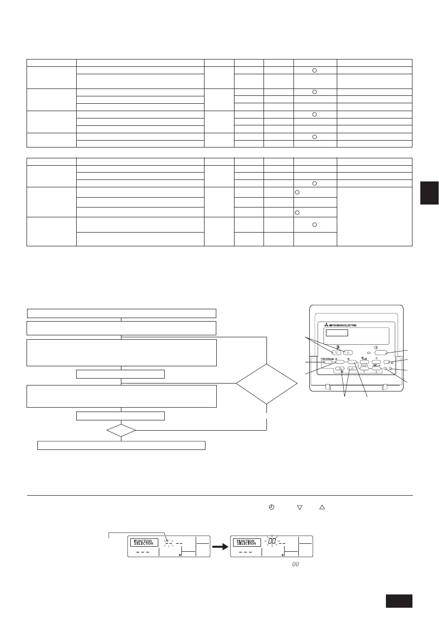
(2) Unit Function Selection
Set the functions of each indoor unit from the remote controller, as required. The functions of each indoor unit can be selected only from the remote controller.
Set the functions by selecting the necessary items from Table 1 and Table 2. (Default settings are also shown below)
Table 1. Itemized functions of the entire refrigerant system (select unit number 00 to 15)
Function
Power failure
automatic recovery
Indoor temperature
detection
LOSSNAY
connectivity
Power voltage
Settings
Not available
Available
Unit operating average
Set by unit’s remote controller
Remote controller’s internal sensor
Not Supported
Supported (unit is not equipped with outdoor-air intake)
Supported (unit is equipped with outdoor-air intake)
240 V
220 V, 230 V
Mode no.
Setting no.
Check
Default settings
1
01
2
1
02
2
3
1
03
2
3
04
1
2
Remarks
Approx. 4-minute wait-period
after power is restored.
Function
Filter sign
Fan operation
during thermo off
in heating
operation
Fan operation
during thermo off
in cooling
operation
Settings
100 Hr
2500 Hr
No filter sign indicator
Mode no.
Setting no.
Check
Default settings
Remarks
1
07
2
3
When selecting fan operation
“Stop”, set setting no. of Mode
no. “02” in Table 1 to “3”. Be sure
to place the remote controller
inside the room to be air-condi-
tioned so that it can monitor the
room temperature.
3
1
25
Operation (Last set fan speed)
Stop
27
1
2
Operation (Last set fan speed)
Table 2. Itemized functions of the indoor unit (select unit numbers 01 to 04 or AL)
Note:
When the indoor unit functions were changed using the function selection after installation is complete, always indicate the set contents by entering j or other
mark in the appropriate check field of Table 1 and Table 2.
2
Stop
Operation (Low speed)
(PEA-400/500)
(PEA-200/250)
[Function selection flow]
First grasp the function selection flow. The following describes setting of “Power voltage” of Table 1 as an example.
(For the actual setting procedure, see [Setting procedure] 1 to 0.)
PAR-21MAA
ON/OFF
FILTER
CHECK
OPERATION
CLEAR
TEST
TEMP.
MENU
BACK
DAY
MONITOR/SET
CLOCK
ON/OFF
F
G
C
D
B
I
A
H
E
1
Check the function selection set contents.
5
Registration (Press button E.)
6
Mode No. Selection ! 04 (Power voltage)
7
Setting No. selection ! 2 (220 V, 230 V)
(Buttons F and G operation)
(Specified indoor unit !
Fan operation)
3
Refrigerant address specification ! 00 (Outdoor unit specification)
(Unnecessary for single refrigerant system.)
4
Unit address No. specification
!
00 (Indoor unit specification)
(Buttons C and D operation)
End?
8
Register (Press button E.)
0
Ending function display (Press buttons A and B simultaneously.)
Change
refrigerant
address and unit
address No.?
9
YES
NO
2
Switch to the FUNCTION SELECTION mode.
(Press A and B simultaneously in the remote controller OFF state.)
YES
NO
[Procedure] (Set only when change is necessary.)
1 Check the set contents of each mode. When the set contents of a mode were changed by function selection, the functions of that mode also change.
Check the set contents as described in steps 2 to 7 and change the setting based on the entries in the Table 1 and Table 2. (Refer default settings, when change the
setting)
2 Set the remote controller to Off.
Press and hold down the A [FILTER] and B [TEST] buttons at the same time
for two seconds or longer.
“FUNCTION SELECTION” blinks for a while, then the remote controller display
changes to the display shown below.
3 Set the outdoor unit refrigerant address No.
When the C [
CLOCK (
) and (
)] buttons are pressed, the refrigerant
address No. decreases and increases between 00 and 15. Set it to the refriger-
ant address No. whose function you want to select.
(This step is unnecessary for single refrigerant system.)
* If the remote controller enters the OFF state after the “FUNCTION SELECTION” and room temperature displays “
” have flashes for two seconds, communication is
probably abnormal. Make sure there are no noise sources near the transmission line.
Note:
If you make a mistake during operation, end function selection by step ? and repeat selection from step 2.
Refrigerant address display
16
G
B
D
K
S
W
N
L
I
E
F
D
R
U
T
R
G
R
P
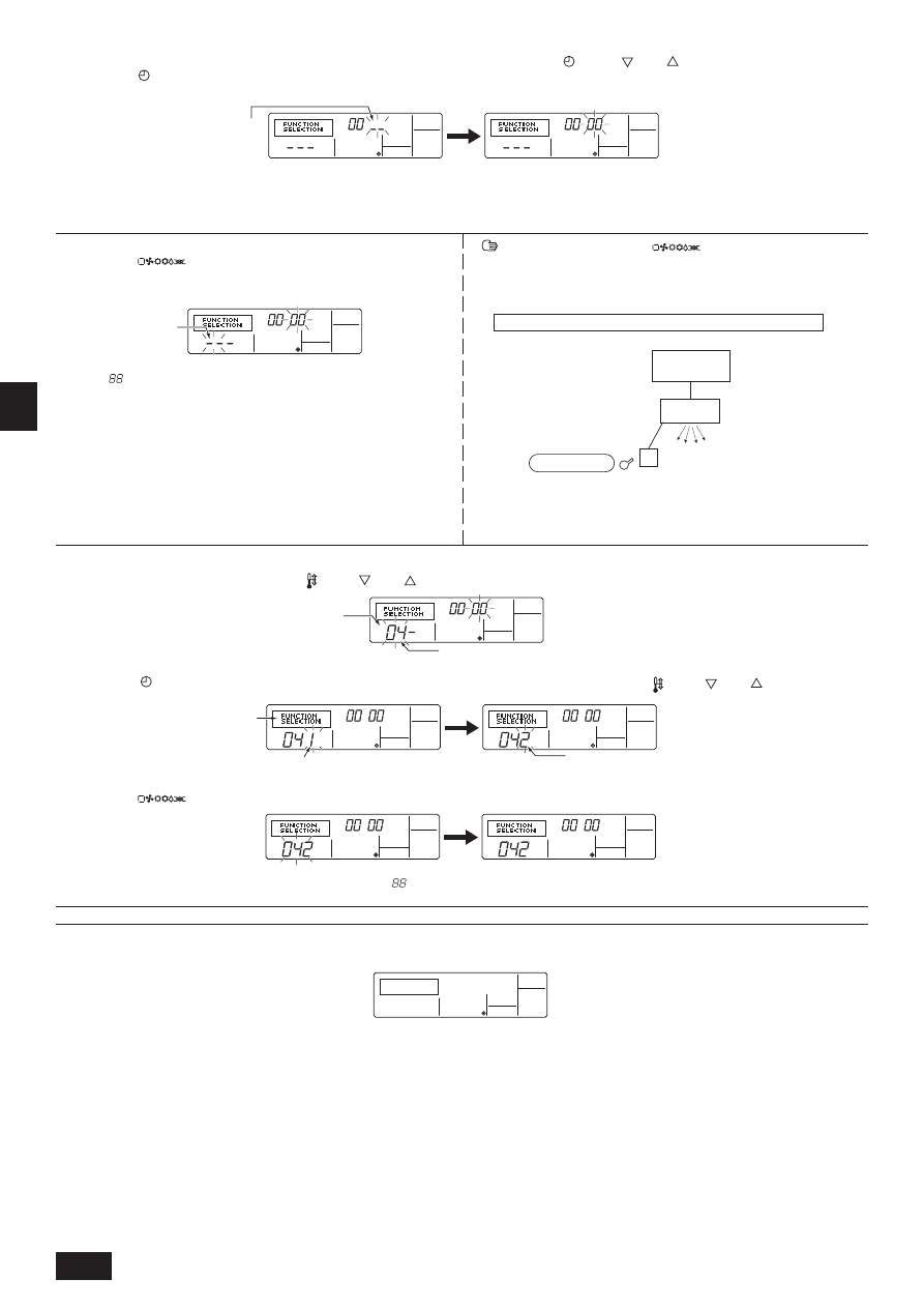
4 Set the indoor unit address No.
Press the D [
ON/OFF] button. The unit address No. display “– –” flashes.
When the C [
CLOCK (
) and (
)] buttons are pressed, the unit address
No. changes in 00 ! 01 ! 02 ! 03 ! 04 ! AL order. Set it to the unit address
No. of the indoor unit whose functions you want to set.
* When setting mode 01 to 04, set the unit address No. to “00”.
* When setting modes 07, 25, 27:
- When setting for each indoor unit, set the unit address No. to “01-04”.
- When batch setting for all indoor units, set the unit address No. to “AL”.
Unit address No. display
5 Refrigerant address and unit address No. registration
Press the E [
] button. The refrigerant address and unit address No.
are registered.
After a while, the mode No. display “– –” flashes.
* When “
” flashes at the room temperature display, the selected refrigerant
address is not in the system.
When “F” is displayed at the unit address No. display, and when it flashes to-
gether with the refrigerant address display, the selected unit address No. does
not exist. Correctly set the refrigerant address and unit address No. by repeat-
ing steps 2 and 3.
When registered using the E [
] button, the registered indoor unit
begins fan operation. When you want to know the location of the indoor units of
the unit address No. whose functions were selected, check here. When the unit
address No. is 00 or AL, all the indoor units of the selected refrigerant address
perform the fan operation.
Ex) When refrigerant address 00, unit address No. = 01 registered
Mode No. display
Outdoor unit
Indoor unit
Refrigerant address 00
Unit address
No. 01
Fan operation
Registration
Remote Controller
* When grouping by different refrigerant systems and an indoor unit other than
the specified refrigerant address performs the fan operation, the refrigerant
address set here is probably duplicated.
Recheck the refrigerant address at the outdoor unit DIP switches.
6
Mode No. selection
Select the mode No. you want to set with the F [
TEMP. (
) and (
)] buttons. (Only the settable mode numbers can be selected.)
7
Select the setting contents of the selected mode.
When the G [
MENU] button is pressed, the current setting No. flashes.
Use this to check the currently set contents.
8
The contents set at steps 3 to 7 are registered.
When the E [
] button is pressed, the mode No. and setting No. flash and registration begins. The flashing mode No. and setting No. change to a steady light
and setting ends.
* When “– –” appears at the mode No. and setting No. displays and “
” flashes at the room temperature display, communication is probably abnormal.
Make sure there are no noise sources near the transmission line.
9
To select more functions, repeat steps 3 to 8.
0
End function selection.
Press and hold down the A [FILTER] and B [TEST] buttons at the same time for two seconds or longer.
After a while, the function selection display disappears and the remote controller returns to the air conditioner off display.
* Do not operate the air conditioner from the remote controller for 30 seconds after the end of function selection.
Note:
When the functions of an indoor unit were changed by function selection after the end of installation, always indicate the set contents by entering a j or other
mark in the appropriate check field of Table 1 and Table 2.
Mode No. 04 = Power voltage
Mode No. display
Setting No. display
Setting No. 1 = 240 V
Setting No. 2 = 220 V, 230 V
Select the setting No. using the F [
TEMP. (
) and (
)] buttons.
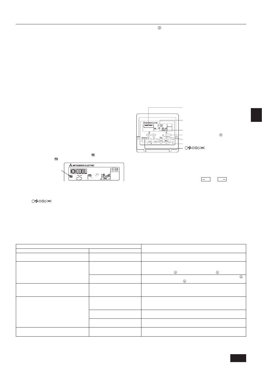
17
G
B
D
K
S
W
N
L
I
E
F
D
R
U
T
R
G
R
P
12. Test run
ON/OFF
TEMP.
˚C
˚C
“CENTRALLY CONTROLLED”
indicator
12.1. Before test run
The test run can be carried out either from the outdoor unit or the indoor unit.
For the test run from outdoor unit, please check the outdoor unit installation manual.
1. Checklist
•
After the installation, piping setup, and wiring of the indoor and outdoor units is
complete, check that refrigerant is not leaking, the power and control wires are
not loose, and the poles are not reversed.
•
Use a 500 V insulation resistance tester to make sure that the resistance be-
tween the power terminal and the ground is 1.0 M" or more. If it is less than
1.0 M", do not operate the unit. * Absolutely do not touch the tester to indoor/
outdoor connection terminals S1, S2, and S3. An accident could occur.
•
Before turning the power ON, make sure that test run switch (SW4) of outdoor
controller board is OFF.
•
Check the electrical power phase. If the phase is reversed, the fan may rotate
in the wrong direction or stop, or unusual sounds may be produced. (PEA-
200, 250, 400, 500)
•
Starting at least 12 hours before the test run, send current through the
crankcase heater. (If the current is running for a shorter period of time,
damage to the compressor could result.)
•
For specific models requiring changing of settings for higher ceilings or selec-
tion of power supply ON/OFF capability, make proper changes referring to the
description for Selection of Functions through Remote Controller.
After the above checks are complete, carry out the test run as indicated in the
following outline.
12.2. Test run procedures
1 Turn on the main power supply
While the display on the remote controller indicates “
”, the remote controller
is disabled. Turn off the “
” indicator before using the remote controller.
2 Press the [TEST] button twice successively within three seconds. Test
run starts.
“TEST RUN” and “OPERATION MODE” are displayed alternately.
3 Press [
] button
Cooling/drying mode: Cool air should start to blow.
Heating mode: Warm air should start to blow (after a while).
4 Check the outdoor unit fan for correct running
The outdoor unit features automatic capacity control to provide optimum fan
speeds. The fan keeps running at a low speed to meet the current outside air
condition unless it exceeds its available maximum power. Then, in actuality,
the fan may stop or run in the reverse direction depending on the outside air,
which does not mean malfunction.
5 Press the [
ON/OFF] button to reset the test run in progress
•
The test run will be automatically shut down after two hours in response to the
AUTO STOP setting of two hours on the timer.
•
During the test run, the room temperature display shows the indoor unit tubing
temperatures.
•
In the case of the test run, the OFF timer will activate, and the test run will
automatically stop after two hours.
•
The room temperature display section shows the control temperature for the
indoor units during the test run.
•
Check that all the indoor units are running properly for simultaneous twin and
triple operation.
Malfunctions may not be displayed even if the wiring is incorrect.
6 Register a telephone number
The telephone number of the repair shop, sales office, etc., to contact if an
error occurs can be registered in the remote controller. The telephone number
will be displayed when an error occurs.
For registration procedures, refer to 11.4 Function selection of remote control-
ler.
Operation mode display
“TEST RUN” and “OPERATION MODE” are
displayed alternately.
Timer stops test run after two hours.
Piping temperature display
Stop test run by pressing the [
ON/OFF] button.
During test run, the RUN lamp remains on.
[TEST] button
[
] button
(*1)
After turning ON the power, the system will go into startup mode, and the remote
controller operation lamp (green) and the display section’s “PLEASE WAIT” will
flash. Also, in the case of the indoor substrate LEDs, LED 1 and LED 2 light up
(when address is 0) or become dim (when address is not 0), and LED 3 flashes. In
the case of the outdoor substrate LED display,
and
are displayed
alternatively at 1-second intervals.
•
If one of the above operations does not function correctly, the following causes
should be considered, and if applicable, dealt with. (The following symptoms
have been determined under test run mode. Note that “startup” in the chart
means the *1 display above.)
Symptoms
Remote Controller Display
Outdoor Substrate LED Display
Cause
Remote controller is displaying “PLEASE WAIT”, and
operation is not possible.
After power is turned ON, “PLEASE WAIT” is dis-
played for 3 mins., then error code is displayed.
Power is turned ON, and “EE” or “EF” are displayed
after “PLEASE WAIT” is displayed.
Display messages do not appear even when remote
controller operation switch is turned ON (operation
lamp does not light up).
Operation display appears but soon disappears even
when remote controller operations are executed.
After “startup” display, “00” is dis-
played (correct operation).
After “startup” display, error code is
displayed.
After “startup” display, “F1” (negative
phase) is displayed.
After “startup” display, “00” or “EE” is
displayed (“EE” is displayed when a
test run is made).
After “startup” display, “EA” (error for
number of units) or “Eb” (unit number
error) is displayed.
After “startup” display, “00” is dis-
played (correct operation).
After “startup” display, “00” is dis-
played (correct operation).
After “startup” display, “00” is dis-
played (correct operation).
• After power is turned ON, system startup lasts for about 2 mins., and
“PLEASE WAIT” is displayed (correct operation).
• Outdoor unit’s safeguard installation connector is open.
• Negative phase and open phase of outdoor unit’s power terminal board
(Single phase: L, N,
/triple phase: L1, L2, L3, N,
)
• Incorrect connection of outdoor terminal board (Single phase: L, N,
/
triple phase: L1, L2, L3, N,
grounding and S1, S2, S3)
• Outdoor unit and indoor unit construction differ.
• Wiring for the indoor and outdoor unit is not connected correctly. (Polarity
is wrong for S1, S2, S3)
• Remote controller transmission wire short
• There is no outdoor unit for address 0 (address is something other than
0).
• Remote controller transmission wire burnout
• After cancellation of function selection, operation is not possible for about
30 secs. (correct operation).
˚C
PAR-21MAA
ON/OFF
FILTER
CHECK
OPERATION
CLEAR
TEST
TEMP.
MENU
BACK
DAY
MONITOR/SET
CLOCK
ON/OFF
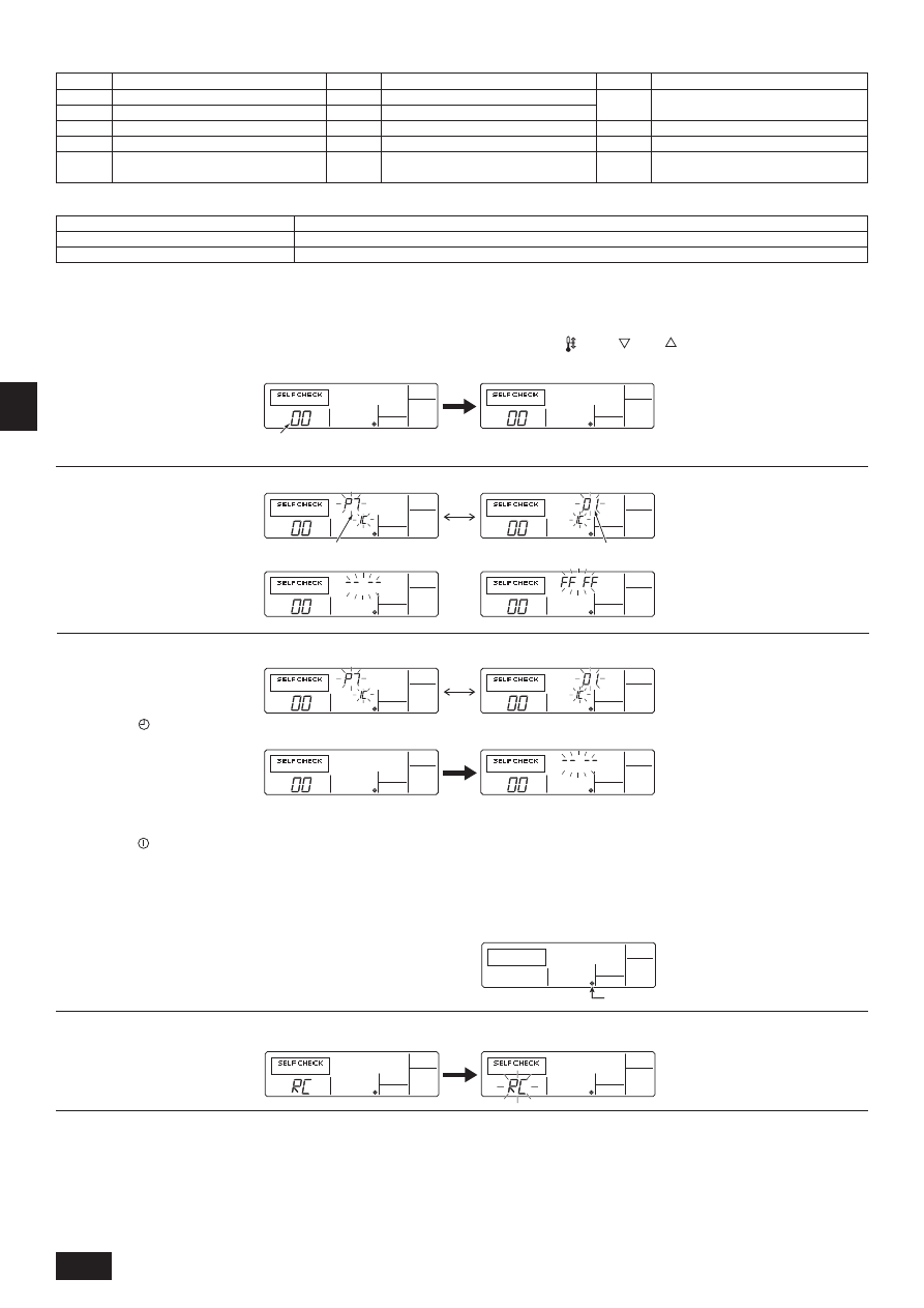
18
G
B
D
K
S
W
N
L
I
E
F
D
R
U
T
R
G
R
P
*
Press the remote controller’s “CHECK” button twice consecutively to be able to run a self-check. See the chart below for content of error code displays.
LCD
Nonconformity Content
E6 ~ EF
Signal error between indoor and outdoor
units
- - - -
No error history
FFFF
No relevant unit
LCD
Nonconformity Content
LCD
Nonconformity Content
P8
Pipe temperature error/Outdoor unit error
P9
Open/short in condenser/evaporater temp thermistor
U0 ~ UP
Outdoor unit nonconformity
F1 ~ FA
Outdoor unit nonconformity
E0 ~ E5
Signal error between remote controller and
indoor unit
P1
Return air temperature sensor error
P2
Pipe (TH2) sensor error
P4
Drain sensor error/Float switch connector open
P5
Drain pump error
P6
Freezing/overheating safeguard operation
See the chart below for details of the LED displays (LED 1, 2, 3) on the indoor substrate.
LED 1 (microcomputer power supply)
Displays the ON/OFF of power for control. Check that this is lit during normal use.
LED 2 (remote controller feed)
Displays the ON/OFF of feed to wired remote controller. Is only lit for indoor unit linked to outdoor unit with address “00”.
LED 3 (indoor and outdoor signals)
Displays signal between indoor and outdoor units. Check that this is flashing during normal use.
12.3. Self-check
Retrieve the error history of each unit using the remote controller.
1
Switch to the self check mode.
When the H [CHECK] button is pressed twice successively within three sec-
onds, the display shown below appears.
2
Set the address or refrigerant address No. you want to self check.
When the F [
TEMP. (
) and (
)] buttons are pressed, the address de-
creases and increases between 01 and 50 or 00 and 15. Set it to the address
No. or refrigerant address No. you want to self check.
Approximately three seconds after the change operation, the self check refrig-
erant address changes from flashing to a steady light and self check begins.
Self check address or self check refrigerant address
3
Self check result display <Error history> (For the contents of the error code, refer to 13. Troubleshooting, error code list.)
4
Error history reset
The error history is displayed in 3 Self check results display.
5
Self check reset
There are the following two ways of resetting self check.
Press the H [CHECK] button twice successively within three seconds ! Resets self check and returns to the state before self check.
Press the I [
ON/OFF] button ! Self check resets and indoor units stop.
(When operation is prohibited, this operation is ineffective.)
Error code 4 digits or error code 2 digits
Address 3 digits or unit address No. 2 digits
<When opposite side does not exist>
<When there is no error history>
When the D [
MENU] button is pressed twice successively within three sec-
onds, the self check address or refrigerant address flashes.
When the error history was reset, the display shown below appears.
When error history reset failed, the error contents are displayed again.
12.4. Remote controller check
If operation cannot be carried out from the remote controller, use this function to diagnose the remote controller.
Power mark
1
First check the power mark.
When normal voltage (DC12 V) is not applied to the remote controller, the power
mark goes off.
When the power mark is off, check the remote controller wiring and the indoor
unit.
2
Switch to the remote controller check mode.
When the H [CHECK] button is held down for five seconds or longer, the dis-
play shown below appears.
When the A [FILTER] button is pressed, remote controller check begins.
ERROR CODE
ERROR CODE
ERROR CODE
ERROR CODE
ERROR CODE
ERROR CODE
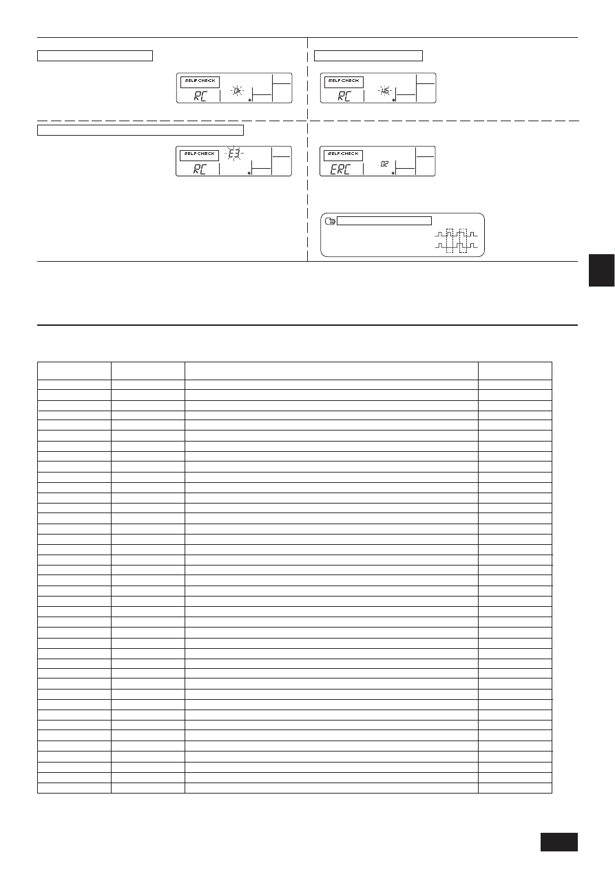
19
G
B
D
K
S
W
N
L
I
E
F
D
R
U
T
R
G
R
P
When remote controller is faulty
(Error display 1) “NG” flashes ! Remote controller send/receive circuit abnormal
Remote controller switching is necessary.
(Error display 3) “ERC” and data error count are displayed ! Data error generation
“Data error count” is the difference between the number of bits of remote controller
send data and the number of bits actually sent to the transmission line. In this case,
the send data was disturbed by the noise, etc. Check the transmission line.
Send data on transmission line
When data error count is 02
Remote controller send data
3
Remote controller check result
When remote controller is normal
Since there is no problem at the remote controller, check for other causes.
When the problem is other than the checked remote controller
(Error code 2) “E3” “6833” “6832” flash ! Cannot send
There is noise on the transmission line, or the indoor unit or another remote con-
troller is faulty. Check the transmission line and the other remote controllers.
4
Remote controller check reset
When the H [CHECK] button is held down for five seconds or longer, remote controller check resets and the “PLEASE WAIT” and RUN lamp flash. Approximately 30
seconds later, the remote controller returns to the state before remote controller check.
13. Troubleshooting
13.1. How to handle problems with the test run
Error code list: details
Remote controller communication – reception error
Remote controller board error
Remote controller communication – transmission error
Remote controller communication – reception error
Remote controller communication – transmission error
Communication between indoor and outdoor units – reception error
Communication between indoor and outdoor units – transmission error
Communication between indoor and outdoor units – reception error
Communication between indoor and outdoor units – transmission error
Indoor/outdoor connection wiring error, indoor unit overload (5 units or more)
Indoor/outdoor connection wiring error (interference, loose)
Excessive time in use
Serial communication error
Serial communication error
Reverse phase, out of phase verification
Faulty input circuit
Duplicated M-NET address setting
M-NET error in PH/W transmission
M-NET bus busy
M-NET communication error with P transmission
M-NET error – no ACK
M-NET error- no response
Undefined error code
Outlet temperature error
CN23 Short-circuit Connector Unplugged
Open/short in discharge temp thermistor
Open/short in liquid temp thermistor
Compressor overcurrent interruption (51C operation)
High pressure error (63H1 operation)
Low pressure error (63L operation)
Power synchronous idle circuit error
Return air temperature sensor error
Pipe (TH2) sensor error
Drain sensor error/Float switch connector open
Drain pump error
Water leak error (PDH only)
Freeze prevention operation
Surge prevention operation
Pipe temperature error/Outdoor unit error
Open/short in condenser/evaporater temp thermistor
Error details
Problem location
Remote Controller
Remote Controller
Remote Controller
Indoor unit
Indoor unit
Indoor unit
Indoor unit
Outdoor unit
Outdoor unit
Outdoor unit
Outdoor unit
Outdoor unit
Outdoor unit
M-NET board
Outdoor unit
Outdoor unit
M-NET board
M-NET board
M-NET board
M-NET board
M-NET board
M-NET board
–
Outdoor unit
Outdoor unit
Outdoor unit
Outdoor unit
Outdoor unit
Outdoor unit
Outdoor unit
Outdoor unit
Indoor unit
Indoor unit
Indoor unit
Indoor unit
Indoor unit
Indoor unit
Indoor unit
Indoor unit
Indoor unit
MELANS display
6831,6834
6201,6202
6832,6833
6831,6834
6832,6833
6740,6843
6841,6842
6840,6843
6841,6842
6844
6845
6846
0403
0403
4103
4115
6600
6602
6603
6606
6607
6608
undefined
1102
1108
5104
5105
4101
1302
1300
4115
5101
5102
2503
2502
2500
1503
1504
1110
5103
Remote controller
display
E0
E1, E2
E3
E4
E5
E6
E7
E8
E9
EA
EB
EC
ED
EE
F1
F8
A0
A2
A3
A6
A7
A8
EF
U2
U2
U3
U4
U6
UE
UL
F8
P1
P2
P4
P5
P5
P6
P6
P8
P9
ERROR CODE

20
G
B
D
K
S
W
N
L
I
E
F
D
R
U
T
R
G
R
P
13.2. The following occurrences are not problems or errors
During thermostat OFF mode, low speed air operation will take place.
During thermostat ON mode, low speed air will switch automatically to set notch (fan
speed) on the basis of time or piping temperature.
During defrosting, the fan will stop.
After the switch is turned ON, low speed air will take place, for 7 minutes (or after pipe
temperature reaches 35°C, 2 minutes) before automatically switch to set notch (fan
speed).
(Hot adjustment)
There is a risk of the power to the outdoor unit being connected in reverse phase. Be
sure to check that the phase is correct.
Ordinary display
Defrosting display
Remote controller display
Problem
Cause
Heating preparations
underway
Ordinary display
When the switch is turned ON, the fan does
not begin to operate. (PEA-200, 250)
The outdoor unit fan turns in reverse or stops,
and an unusual sound is heard.
The fan setting changes during heating.
(PEA-200, 250)
The fan stops during heating.
Note:
If the fan in the indoor unit does not operate, check the over-current relay on the fan motor to determine whether it has been tripped.
If the over-current relay has been tripped, reset it after eliminating the cause of the problem (e.g. motor lock).
To reset the over-current relay, open the control box and press the green claw on bottom-right of the relay until a click is heard. Release the claw and check that
it returns to its original position.
Note that if it is pressed too hard it will not return to its original position.
Wyszukiwarka
Podobne podstrony:
BWE0704A PartsList PEA RP200 500GA TH AF Apr 2009
IM PAC SE51CRB WT03594X05 GB Aug 2009
IM PKFY P32 50VHM E RG79D439H03 Aug 2009
IM CMY Q100VBK WT05688X01 GB Aug 2009
IM PFAV P250 900VM E WT05474X02 Oct 2009
IM PCA RP2 6GA BG79U334H01 Aug 2004
IM PAR W21MAA WT05312X01 GB Aug 2008
IM PUHZ RP200 250YHA BG79U638H01
IM PKA RP60 100KAL RG79D349H01 Jul 2009
IM PEH RP200 250MYA WT04594X01 2oo5
IM PCA RP50 140KA RG79D451H01 Jul 2009
IM PUHZ RP200 250YHA BG79U637H03 GB 03 2007
BWE09210 PARTS PEFY P20 140AMA ER1 VMAL ER1 Aug 2009
Biogasanlagen im EEG 2009
IM jednolity tekst 2009
ZESPÓŁ SZKÓŁ PONADGIMNAZJALNYCH NR l IM, 12.PRACA W SZKOLE, ZSG NR 1 2008-2009
Materialy do seminarium IM 2009 10 czesc I
więcej podobnych podstron