Air-Conditioners
PKA-RP·KAL
INSTALLATION MANUAL
For safe and correct use, read this manual and the outdoor unit installation manual thoroughly before installing
the air-conditioner unit.
INSTALLATIONSHANDBUCH
Aus Sicherheitsgründen und zur richtigen Anwendung vor Installation der Klimaanlage die vorliegende
Bedienungsanleitung und das Installationshandbuch gründlich durchlesen.
MANUEL D’INSTALLATION
Avant d’installer le climatiseur, lire attentivement ce manuel, ainsi que le manuel d’installation de l’appareil
extérieur pour une utilisation sûre et correct.
INSTALLATIONSMANUAL
Läs bruksanvisningen och utomhusenhetens installationshandbok noga innan luftkonditioneringen installeras så
att den används på ett säkert och korrekt sätt.
INSTALLATIEHANDLEIDING
Lees deze handleiding en de installatiehandleiding van het buitenapparaat zorgvuldig door voordat u met het
installeren van de airconditioner begint.
MANUALE DI INSTALLAZIONE
Per un uso sicuro e corretto, prima di installare il condizionatore d’aria leggere attentamente il presente
manuale ed il manuale d’installazione dell’unità esterna.
MANUAL DE INSTALACIÓN
Para un uso seguro y correcto, lea detalladamente este manual de instalación antes de montar la unidad de
aire acondicionado.
MANUAL DE INSTALAÇÃO
Para uma utilização segura e correcta, leia atentamente este manual e o manual de instalação da unidade
exterior antes de instalar o aparelho de ar condicionado.
INSTALLATIONSMANUAL
Læs af sikkerhedshensyn denne manual samt manualen til installation af udendørsenheden grundigt, før du
installerer klimaanlægget.
E!XEIPI"IO O"H!I#N E!KATA$TA$H$
!"# $%$&' (#" #$)#*' +,'$-, ."#/0$&1 2,3$1(&"(0 #4&5 &3 16+1",7."3, (#89: (#" &3 16+1",7."3 16(#&0$&#$-:
&-: 1;%&1,"(': <3=0.#:, 2,"= #25 &-= 16(#&0$&#$- &-: <3=0.#: (*"<#&"$&"(3>.
MONTAJ ELK%TABI
Emniyetli ve do?ru kullanõm için, klima cihazõnõ monte etmeden önce bu kõlavuzu ve dõ@ ünite montaj kõlavuzunu
tamamõyla okuyun.
&'()*)+,-*) .) ',-/0)*(1
ABC DEFGHFIFJKC EFLDHMGJDN K JMOBFPMQFN RSGHBTMUMVKK WJKXMUFBYJD HZDIUKUF OMJJDF ZTSDWDOGUWD K
ZTSDWDOGUWD HD TGUMJDWSF JMZTPJD[D HZKEDZM HFZFO TGUMJDWSDN SDJOKVKDJFZM.
FOR INSTALLER
FÜR INSTALLATEURE
POUR L’INSTALLATEUR
FÖR INSTALLATÖREN
VOOR DE INSTALLATEUR
PER L’INSTALLATORE
PARA EL INSTALADOR
PARA O INSTALADOR
TIL INSTALLATØREN
!23 34567 864 937:2 5;7 :!9353$53$;
MONTÖR %Ç%N
+<= ',-/0)*>-1<=
English
Deutsch
Français
Nederlands
Español
Italiano
:??@ABCD
Português
Dansk
Svenska
Türkçe
&EFFGHI
Ҿጎຫກ
ҾጎۙഗኮമLj൩ံཚ܁ԨຫກࢅྔऐፇҾጎຫກLjᅜՍҾඇኟඓں๑ᆩԨऐă
Ҿጎටᇵᆩ
ዐ࿔
2
! Before installing the unit, make sure you read all the “Safety
precautions”.
! Please report to your supply authority or obtain their consent before
connecting this equipment to the power supply system.
Warning:
Describes precautions that must be observed to prevent danger of injury or
death to the user.
Caution:
Describes precautions that must be observed to prevent damage to the unit.
Contents
Warning:
• Ask a dealer or an authorized technician to install the unit.
• For installation work, follow the instructions in the Installation Manual and
use tools and pipe components specifically made for use with refrigerant
specified in the outdoor unit installation manual.
• The unit must be installed according to the instructions in order to
minimize the risk of damage from earthquakes, typhoons, or strong winds.
An incorrectly installed unit may fall down and cause damage or injuries.
• The unit must be securely installed on a structure that can sustain its
weight.
• If the air conditioner is installed in a small room, measures must be taken
to prevent the refrigerant concentration in the room from exceeding the
safety limit in the event of refrigerant leakage. Should the refrigerant leak
and cause the concentration limit to be exceeded, hazards due to lack of
oxygen in the room may result.
• Ventilate the room if refrigerant leaks during operation. If refrigerant
comes into contact with a flame, poisonous gases will be released.
• All electric work must be performed by a qualified technician according to
local regulations and the instructions given in this manual.
• Use only specified cables for wiring.
• The terminal block cover panel of the unit must be firmly attached.
• Use only accessories authorized by Mitsubishi Electric and ask a dealer or
an authorized technician to install them.
• The user should never attempt to repair the unit or transfer it to another
location.
• After installation has been completed, check for refrigerant leaks. If
refrigerant leaks into the room and comes into contact with the flame of a
heater or portable cooking range, poisonous gases will be released.
1.1. Before installation (Environment)
Caution:
• Do not use the unit in an unusual environment. If the air conditioner is
installed in areas exposed to steam, volatile oil (including machine oil), or
sulfuric gas, areas exposed to high salt content such as the seaside, the
performance can be significantly reduced and the internal parts can be
damaged.
• Do not install the unit where combustible gases may leak, be produced,
flow, or accumulate. If combustible gas accumulates around the unit, fire
or explosion may result.
• Do not keep food, plants, caged pets, artwork, or precision instruments in
the direct airflow of the indoor unit or too close to the unit as these items
can be damaged by temperature changes or dripping water.
• When the room humidity exceeds 80% or when the drainpipe is clogged,
water may drip from the indoor unit. Do not install the indoor unit where
such dripping can cause damage.
• When installing the unit in a hospital or communications office, be
prepared for noise and electronic interference. Inverters, home appliances,
high-frequency medical equipment, and radio communications equipment
can cause the air conditioner to malfunction or breakdown. The air
conditioner may also affect medical equipment, disturbing medical care,
and communications equipment, harming the screen display quality.
1. Safety precautions
After installation work has been completed, explain the “Safety precautions,” use,
and maintenance of the unit to the customer according to the information in the
Operation Manual and perform the test run to ensure normal operation. Both the
Installation Manual and Operation Manual must be given to the user for keeping.
These manuals must be passed on to subsequent users.
: Indicates a part which must be grounded.
Warning:
Carefully read the labels affixed to the main unit.
1.4. Before starting the test run
Caution:
• Turn on the main power switch more than 12 hours before starting
operation. Starting operation just after turning on the power switch can
severely damage the internal parts.
• Before starting operation, check that all panels, guards and other
protective parts are correctly installed. Rotating, hot, or high voltage parts
can cause injuries.
• Do not operate the air conditioner without the air filter set in place. If the
air filter is not installed, dust may accumulate and breakdown may result.
• Do not touch any switch with wet hands. Electric shock may result.
• Do not touch the refrigerant pipes with bare hands during operation.
• After stopping operation, be sure to wait at least five minutes before turning
off the main power switch. Otherwise, water leakage or breakdown may
result.
1.3. Before electric work
Caution:
• Be sure to install molded case circuit brakers. If not installed, electric
shock may result.
• For the power lines, use standard cables of sufficient capacity. Otherwise,
a short circuit, overheating, or fire may result.
• When installing the power lines, do not apply tension to the cables.
• Be sure to ground the unit. If the unit is not properly grounded, electric
shock may result.
• Use circuit breakers (ground fault interrupter, isolating switch (+B fuse),
and molded case circuit breaker) with the specified capacity. If the circuit
breaker capacity is larger than the specified capacity, breakdown or fire
may result.
1.2. Before installation or relocation
Caution:
• Be extremely careful when transporting the units. Two or more persons
are needed to handle the unit as it weighs 20 kg or more. Do not grasp the
packaging bands. Wear protective gloves as you can injure your hands on
the fins or other parts.
• Be sure to safely dispose of the packaging materials. Packaging materials,
such as nails and other metal or wooden parts may cause stabs or other
injuries.
• Thermal insulation of the refrigerant pipe is necessary to prevent
condensation. If the refrigerant pipe is not properly insulated, condensation
will be formed.
• Place thermal insulation on the pipes to prevent condensation. If the
drainpipe is installed incorrectly, water leakage and damage to the ceiling,
floor, furniture, or other possessions may result.
• Do not clean the air conditioner unit with water. Electric shock may result.
• Tighten all flare nuts to specification using a torque wrench. If tightened
too much, the flare nut can break after an extended period.
1. Safety precautions .............................................................................................2
2. Installation location ............................................................................................3
3. Installing the indoor unit ....................................................................................3
4. Installing the refrigerant piping ..........................................................................7
5. Drainage piping work .........................................................................................8
6. Electrical work ...................................................................................................9
7. Test run ............................................................................................................14
8. Easy maintenance function (Option) ...............................................................16
3
2. Installation location
3. Installing the indoor unit
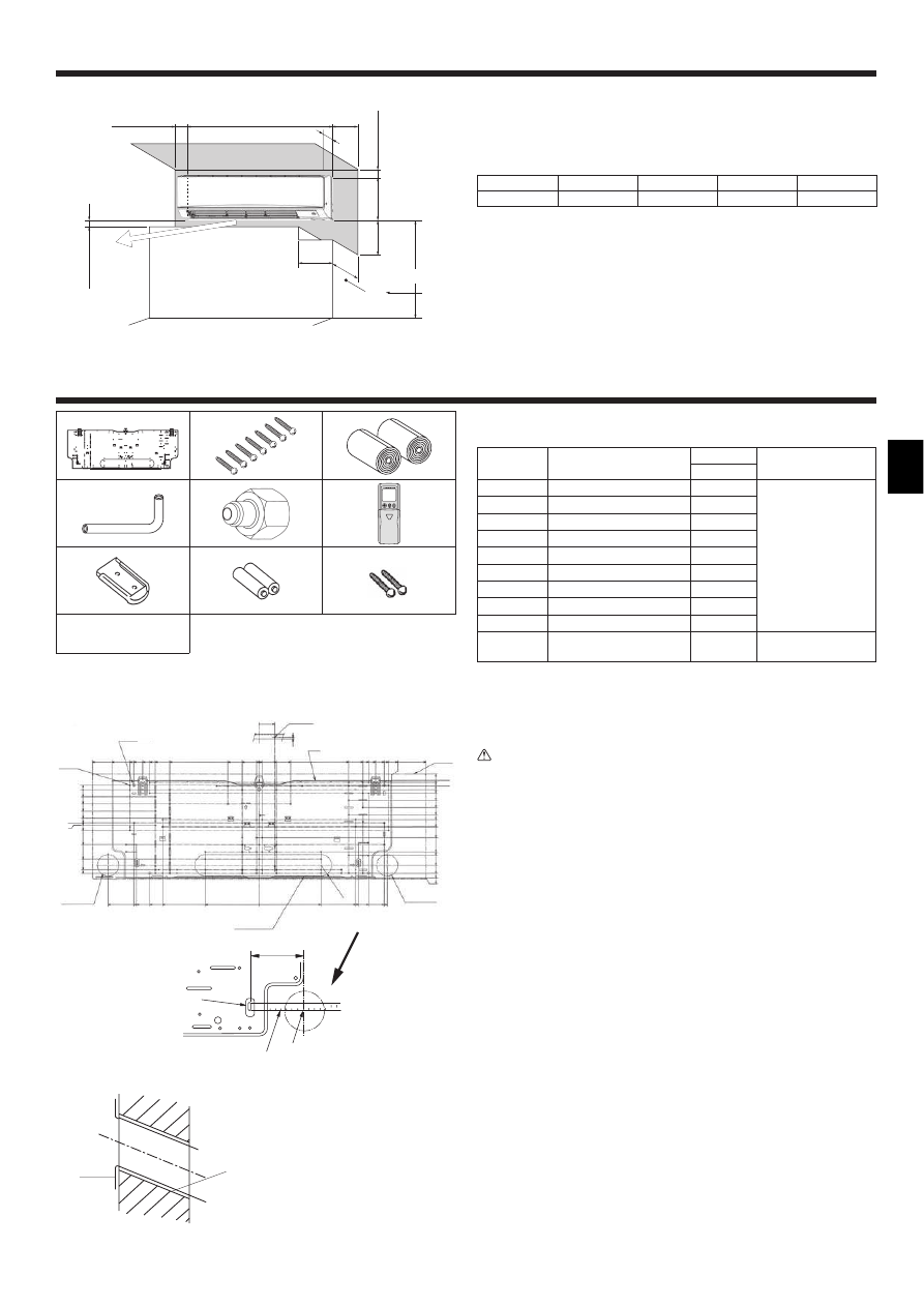
3.1. Check the indoor unit accessories (Fig. 3-1)
The indoor unit should be supplied with the following accessories.
PART NUMBER
ACCESSORY
QUANTITY
LOCATION OF
SETTING
60, 71, 100
1
Mount board
1
Fix at the back of the
unit
2
Tapping screw 4 ! 25
7
3
Felt tape
2
4
L-shaped connection pipe
1
5
Charge nut
1
6
Wireless remote controller
1
7
Remocon holder
1
8
Alkali batteries (size AAA)
2
9
Tapping screw 3.5 ! 16
2
0
Spacer
1
Make use of
packaging material
3.2. Installing the wall mounting fixture (Fig. 3-2)
3.2.1. Setting the wall mounting fixture and piping positions
! Using the wall mounting fixture, determine the unit’s installation position
and the locations of the piping holes to be drilled.
Warning:
Before drilling a hole in the wall, you must consult the building contractor.
! PKA-RP60, 71, 100KAL
A Mount board 1
B Indoor unit
C Bottom left rear pipe hole (ø75-ø80)
D Bottom right rear pipe hole (ø75-ø80)
E Knockout hole for left rear hole (75 × 480)
F Bolt hole (4-ø9 hole)
G Center measurement hole (ø2.5 hole)
H Tapping hole (75-ø5.1 hole)
I Hole centre
J Align the scale with the line.
K Insert scale.
3.2.2. Drilling the piping hole (Fig. 3-3)
! Use a core drill to make a hole of 75-80 mm diameter in the wall in the
piping direction, at the position shown in the diagram to the left.
! The hole should incline so that the outside opening is lower than the
inside opening.
! Insert a sleeve (with a 75 mm diameter and purchased locally) through the
hole.
Note:
The purpose of the hole’s inclination is to promote drain flow.
Fig. 2-1
2.1. Outline dimensions (Indoor unit) (Fig. 2-1)
Select a proper position allowing the following clearances for installation and
maintenance.
! PKA-RP60, 71, 100KAL
(mm)
A
B
C
D
E
Min. 100.5
Min. 22.4
Min. 48
Min. 250
Min. 220
F Air outlet: Do not place an obstacle within 1500 mm of the air outlet.
G Floor surface
H Furnishing
I When the projection dimension of a curtain rail or the like from the wall exceeds 60 mm,
extra distance should be taken because the fan air current may create a short cycle.
J 1800 mm or greater from the floor surface (for high location mounting)
K 108 mm or greater with left or rear left piping and optional drain pump installation
L 550 mm or greater with optional drain pump installation
M Minimum 7 mm: 265 mm or greater with optional drain pump installation
Fig. 3-1
! PKA-RP60, 71, 100KAL
Fig. 3-2
A
K
J
I
100m
25
0
12.5
37.5
62.5
87.5
104.5
129.5
167
217
229.5
264
292
308.5
311
54
585
465.5
454
439
408.5
384.5
364
314
110
54
0
3
60
10
0
10
60
110
314
364
384
408.5
439
454
517.4
585
530.5
439
430.5
384
339
189
0
216.5
339
R37.5
349.2
384
439
449.2
15.5
0
25
50
75
100
117
125
142
192
242
279.5
292
A
B
C
H
F
G
D
E
(mm)
! PKA-RP60, 71, 100KAL
Fig. 3-3
A
C
D
E
B
A Sleeve
B Hole
C (Indoors)
D Wall
E (Outdoors)
G
F
A
B
L
1170
365
H
E
J
*
M
I
D
C
295
K
(mm)
1
2
3
4
5
6
7
8
9
0
–
4
3. Installing the indoor unit
Fig. 3-4
A
B
C
D
I
G
F
H
E
! PKA-RP60, 71, 100KAL
Fig. 3-5
Fig. 3-7
Fig. 3-6
A
A
Fig. 3-8
A
B
D
C
E
Fig. 3-10
Fig. 3-9
B
A
C
D
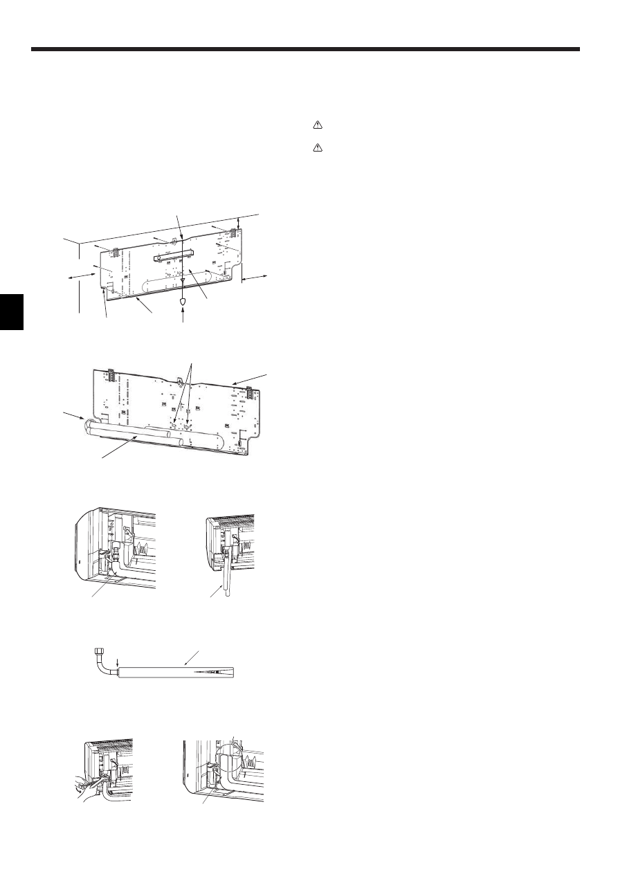
3.2.3. Installing the wall mounting fixture
! Since the indoor unit weighs near 21 kg, selection of the mounting
location requires thorough consideration. If the wall does not seem to be
strong enough, reinforce it with boards or beams before installation.
! The mounting fixture must be secured at both ends and at the centre, if
possible. Never fix it at a single spot or in any nonsymetrical way.
(If possible, secure the fixture at all the positions marked with a bold arrow.)
Warning:
If possible, secure the fixture at all positions indicated with a bold arrow.
Caution:
• The unit body must be mounted horizontally.
• Fasten at the holes marked with " as shown by the arrows.
! PKA-RP60, 71, 100KAL (Fig. 3-4)
A Min. 90 mm (617.6 mm or greater with optional drain pump installation)
B Min. 200 mm
C Min. 70 mm (130 mm or greater with left, rear left, or lower left piping, and optional drain
pump installation)
D Fixing screws (4 × 25) 2
E Level
F Fasten a thread to the hole.
G Place the level against the horizontal reference line of the mount board and mount so that it is
level. Hang a weight from the thread and align with # EPK of the mount board to permit leveling.
H Weight
I Mount board 1
3.3. When embedding pipes into the wall (Fig. 3-5)
• The pipes are on the bottom left.
• When the cooling pipe, drain pipes internal/external connection lines etc are to
be embedded into the wall in advance, the extruding pipes etc, may have to be
bent and have their length modified to suit the unit.
• Use marking on the mount board as a reference when adjusting the length of the
embedded cooling pipe.
• During construction, give the length of the extruding pipes etc some leeway.
A Mount board 1
B Reference marking for flare connection
C Through hole
D On-site piping
3.4. Preparing the indoor unit
* Check beforehand because the preparatory work will differ depending on the
exiting direction of the piping.
* When bending the piping, bend gradually while maintaining the base of the
piping exiting portion. (Abrupt bending will cause misshaping of the piping.)
! PKA-RP60, 71, 100KAL
Attachment of L-shaped connection pipe 4
Right, left and rear piping (Fig. 3-6)
1. Remove the flare nut and cap of the indoor unit. (Gas pipe only)
2. Apply refrigerating machine oil to the flare sheet surface. (Preparation on
location)
3. Facing the direction in which the L-shaped connection pipe 4 will be removed,
make a quick connection to the indoor unit flare connection opening.
4. Tighten the flare nut using a double open-end wrench. (Fig. 3-9)
Tightening force: 68 to 82 N•m
5. Attach the charge nut 5 to the liquid pipe side joint portion, and check for
leakage of the L-shaped connection pipe 4 connection portion.
Remove the charge nut 5 after completion of the work.
Tightening force: 34 to 42 N•m
6. Cover the flare connection portion with the pipe cover of the L-shaped
connection pipe 4 so that it is not exposed. (Fig. 3-10)
A L-shaped connection pipe 4
B Cut-off position (Straight pipe portion)
C Tightening direction
D Cover with pipe cover
E Cover the flare nut connection portion with the pipe cover.
Lower piping (Fig. 3-7)
1. Cut L-shaped connection pipe 4 at the position indicated in (Fig. 3-8).
2. Insert the flare nut that was removed earlier onto the straight pipe side of the cut
L-shaped connection pipe 4 and then flare the end of the pipe.
3. Remove the flare nut and cap of the indoor unit. (Gas pipe only)
4. Apply refrigerating machine oil to the flare sheet surface. (Preparation on
location)
5. Quickly connect the L-shaped connection pipe 4 that has been processed as
described in part 2) to the indoor unit flare connection opening.
6. Tighten the flare nut using a double open-end wrench. (Fig. 3-9)
Tightening force: 68 to 82 N•m
7. Attach the charge nut 5 to the liquid pipe side joint portion, and check for
leakage of the L-shaped connection pipe 4 connection portion.
Remove the charge nut 5 after completion of the work.
Tightening force: 34 to 42 N•m
8. Cover the flare connection portion with the pipe cover of the L-shaped
connection pipe 4 so that it is not exposed. (Fig. 3-10)
5
3. Installing the indoor unit
Fig. 3-11
B
A
C
E
D
Leakage check of the L-shaped connection pipe connection portion
1. Attach the charge nut 5 to the liquid pipe side joint portion.
Tightening force: 34 to 42 N•m
2. Pressurize by filling with nitrogen gas from the charge nut.
Do not pressurize to the current constant pressure all at once. Pressurize
gradually.
1) Pressurize to 0.5 MPa, wait five minutes, and make sure the pressure does
not decrease.
2) Pressurize to 1.5 MPa, wait five minutes, and make sure the pressure does
not decrease.
3) Pressurize to 4.15 MPa and measure the surrounding temperature and
refrigerant pressure.
3. If the specified pressure holds for about one day and does not decrease, the
pipes have passed the test and there are no leaks.
• If the surrounding temperature changes by 1°C, the pressure will change by
about 0.01 MPa. Make the necessary corrections.
4. If the pressure decreases in steps (2) or (3), there is a gas leak. Look for the
source of the gas leak.
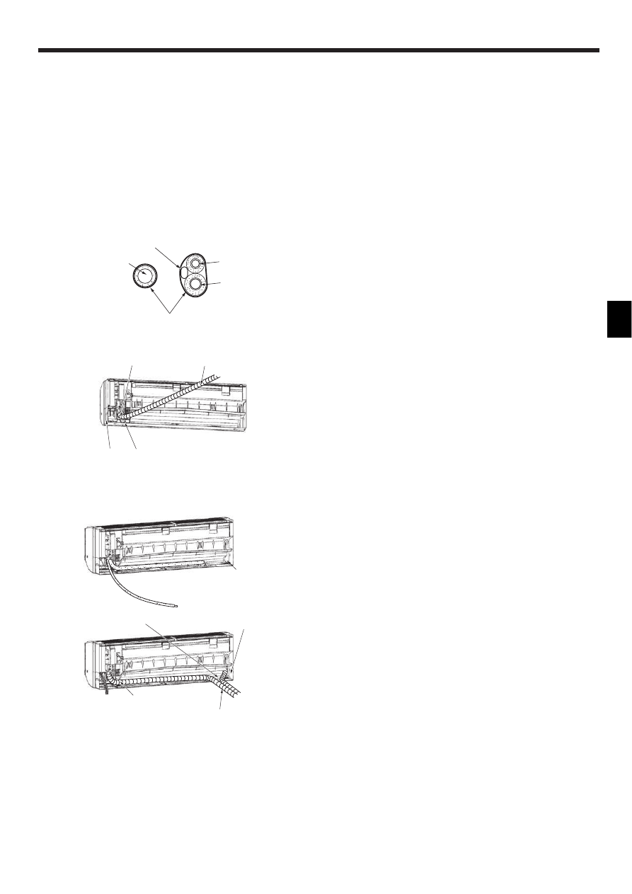
Extraction and processing of the piping and wiring (Fig. 3-11)
1. Connection of indoor/outdoor wiring $ See page. 9.
2. Wrap the felt tape 3 in the range of the refrigerant piping and drain hose which
will be housed within the piping space of the indoor unit.
• Wrap the felt tape 3 securely from the base for each of the refrigerant piping
and the drain hose.
• Overlap the felt tape 3 at one-half of the tape width.
• Fasten the end portion of the wrapping with vinyl tape.
A Liquid pipe
B Gas pipe
C Indoor/outdoor connection cable
D Drain hose
E Felt tape 3
3. Be careful that the drain hose is not raised, and that contact is not made with the
indoor unit box body.
Do not pull the drain hose forcefully because it might come out.
Rear, right and lower piping (Fig. 3-12)
1) Be careful that the drain hose is not raised, and that contact is not made with
the indoor unit box body.
Arrange the drain hose at the underside of the piping and wrap it with felt
tape 3.
2) Securely wrap the felt tape 3 starting from the base. (Overlap the felt tape at
one-half of the tape width.)
A Cut off for right piping.
B Cut off for lower piping.
Left and left rear piping (Fig. 3-13)
4. Drain hose replacement $ See 8. Drainage piping work
Be sure to replace the drain hose and the drain cap for the left and rear left
piping. Dripping may occur if you forget to install or fail to replace these parts.
C Drain cap
1) Be careful that the drain hose is not raised, and that contact is not made with
the indoor unit box body.
2) Securely wrap the felt tape 3 starting from the base. (Overlap the felt tape at
one-half of the tape width.)
3) Fasten the end portion of the felt tape 3 with vinyl tape.
D Cut off for left piping.
Fig. 3-12
Fig. 3-13
B
A
1)
2)
C
D
1)
3)
2)
6
Fig. 3-14
Fig. 3-15
Fig. 3-16
C
B
A
E
D
! PKA-RP60, 71, 100KAL
B
A
C
D
A
C
B
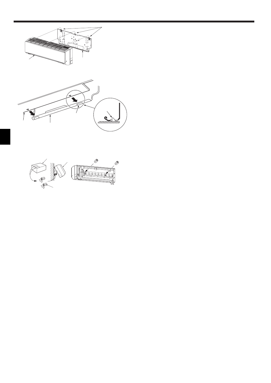
3.5. Mounting the indoor unit
1. Affix the mount board 1 to the wall.
2. Hang the indoor unit on the hook positioned on the upper part of the mount
board.
Rear, right and lower piping (Fig. 3-14)
3. While inserting the refrigerant piping and drain hose into the wall penetration
hole (penetration sleeve), hang the top of the indoor unit to the mount board 1.
4. Move the indoor unit to the left and right, and verify that the indoor unit is hung
securely.
5. Fasten by pushing the bottom part of the indoor unit onto the mount board 1.
(Fig. 3-15)
* Check that the knobs on the bottom of the indoor unit are securely hooked into
the mount board 1.
6. After installation, be sure to check that the indoor unit is installed level.
A Mount board 1
B Indoor unit
C Hook
D square hole
Left and left rear piping (Fig. 3-16)
3. While inserting the drain hose into the wall penetration hole (penetration sleeve),
hang the top of the indoor unit to the mount board 1.
Giving consideration to the piping storage, move the unit all the way to the left
side, then cut part of the packaging carton and wrap into a cylindrical form as
illustrated in the diagram. Hook this to the rear surface rib as a spacer, and raise
the indoor unit.
4. Connect the refrigerant piping with the site-side refrigerant piping.
5. Fasten by pushing the bottom part of the indoor unit onto the mount board 1.
* Check that the knobs on the bottom of the indoor unit are securely hooked into
the mount board 1.
6. After installation, be sure to check that the indoor unit is installed level.
A Indoor unit
B Packaging carton
C Cut off
D Wrap into a cylindrical form
E Fasten with tape
3. Installing the indoor unit
7
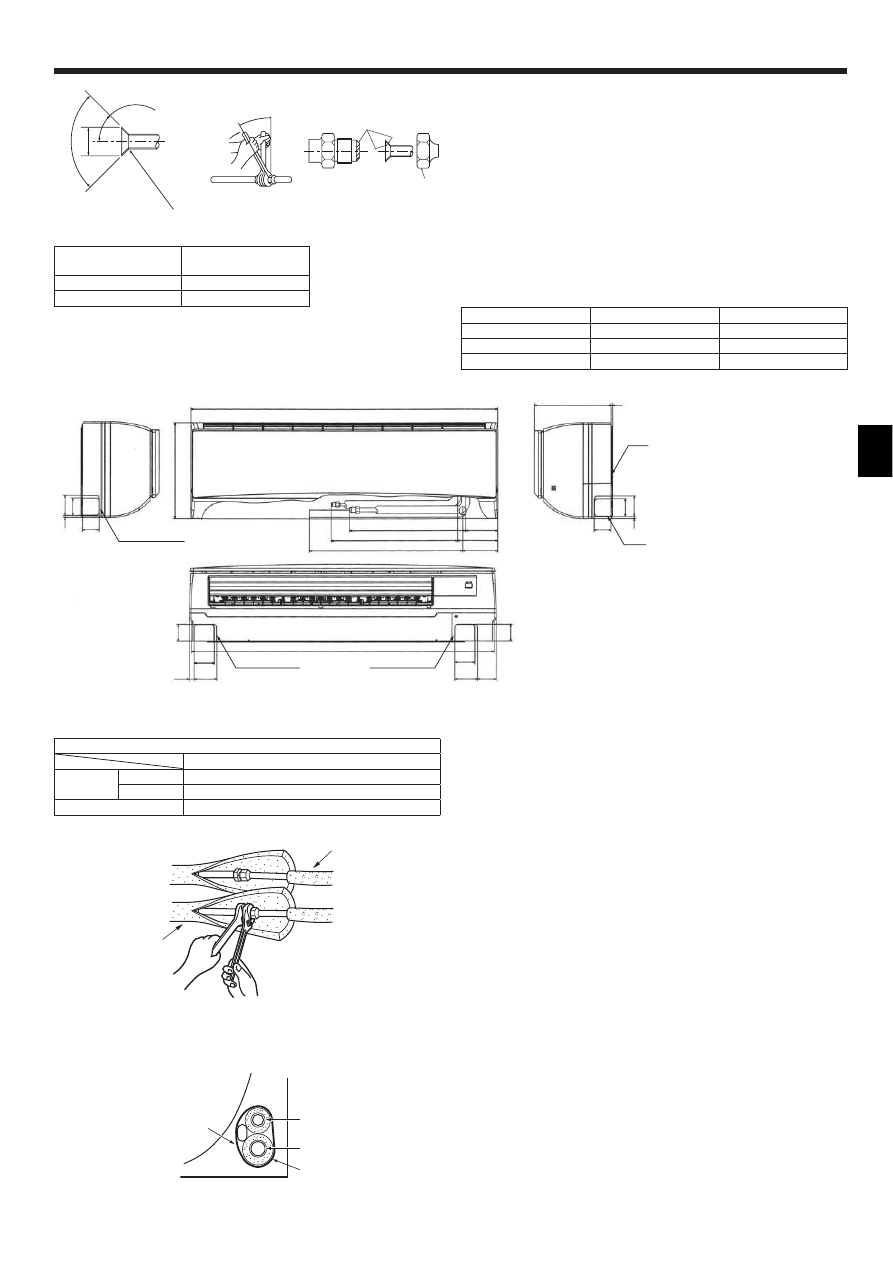
4. Installing the refrigerant piping
A Flare cutting dimensions
Copper pipe O.D.
(mm)
Flare dimensions
øA dimensions (mm)
ø9.52
12.8 - 13.2
ø15.88
19.3 - 19.7
90°±0.5°
øA
R0.4~R0.8
A
45±2°
B
C
D
Fig. 4-1
Fig. 4-2
D
65
7
7
7
.8
6
7
3
6
5
1170
444 (A)*
123
482 (B)
154
585 (C)
1155
6
5
6
5
77
87
F
F
77
87
71.2
18.2
134
295
5
65
6
7
7
7
7
.8
G
E
4.1. Connecting pipes (Fig. 4-1)
• When commercially available copper pipes are used, wrap liquid and gas pipes
with commercially available insulation materials (heat-resistant to 100 °C or
more, thickness of 12 mm or more).
• The indoor parts of the drain pipe should be wrapped with polyethylene foam
insulation materials (specific gravity of 0.03, thickness of 9 mm or more).
• Apply thin layer of refrigerant oil to pipe and joint seating surface before
tightening flare nut.
• Use two wrenches to tighten piping connections.
• Use refrigerant piping insulation provided to insulate indoor unit connections.
Insulate carefully.
B
Flare nut tightening torque
C
Do not apply refrigerating machine oil to the screw portions.
(This will make the flare nuts more apt to loosen.)
D
Be certain to use the flare nuts that are attached to the main unit.
(Use of commercially-available products may result in cracking.)
Copper pipe O.D.
Flare nut O.D.
Tightening torque
(mm)
(mm)
(N·m)
ø9.52
22
34 - 42
ø15.88
29
68 - 82
! PKA-RP60, 71, 100KAL
Fig. 4-3
Fig. 4-4
! PKA-RP60, 71, 100KAL
B
A
D
C
B
A
4.2. Indoor unit
Refrigerant and Drainage Piping Sizes
Item
Model
PKA-RP60, 71, 100KAL
Refrigerant
piping
Liquid
ODø9.52 (3/8")
Gas
ODø15.88 (5/8")
Drainage piping
ODø16
4.3. Positioning refrigerant and drain piping (Fig. 4-2)
! PKA-RP60, 71, 100KAL
A Gas pipe
* Indicates the condition with accessories mounted.
B Liquid pipe
C Drain hose
D Left-side piping knockout hole
E Right-side piping knockout hole
F Lower piping knockout hole
G Mount board 1
4.4. Refrigerant piping (Fig. 4-3)
Indoor unit
1. Remove the flare nut and cap of the indoor unit.
2. Make a flare for the liquid pipe and gas pipe and apply refrigerating machine oil
(available from your local supplier) to the flare sheet surface.
3. Quickly connect the on site cooling pipes to the unit.
4. Wrap the pipe cover that is attached to the gas pipe and make sure that the
connection join is not visible.
5. Wrap the pipe cover of the unit’s liquid pipe and make sure that it covers the
insulation material of the on site liquid pipe.
6. The portion where the insulation material is joined is sealed by taping.
A Site-side refrigerant piping
B Unit side refrigerant piping
4.4.1. Storing in the piping space of the unit (Fig.4-4)
1. Wrap the supplied felt tape in the range of the refrigerant piping which will be
housed within the piping space of the unit to prevent dripping.
2. Overlap the felt tape at one-half of the tape width.
3. Fasten the end portion of the wrapping with vinyl tape, etc.
A Gas pipe
B Liquid pipe
C Indoor/outdoor connection cable
D Felt tape 3
8
Fig. 5-1
5. Drainage piping work
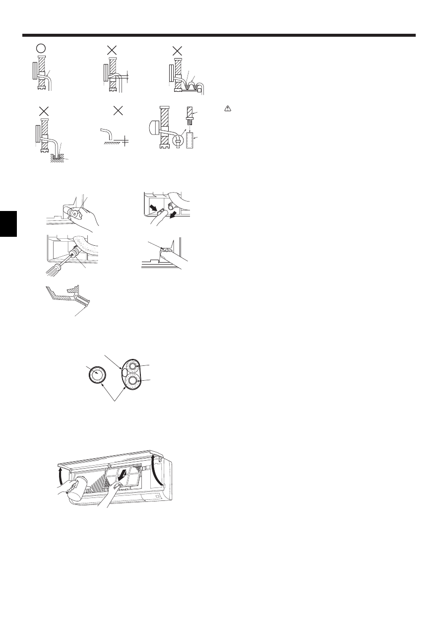
5.1. Drainage piping work (Fig. 5-1)
• Drain pipes should have an inclination of 1/100 or more.
• For extension of the drain pipe, use a soft hose (inner dia. 15 mm) available on
the market or hard vinyl chloride pipe (VP-16/O.D. ø22 PVC TUBE). Make sure
that there is no water leakage from the connections.
• Do not put the drain piping directly in a drainage ditch where sulphuric gas may
be generated.
• When piping has been completed, check that water flows from the end of the
drain pipe.
Caution:
The drain pipe should be installed according to this Installation Manual to
ensure correct drainage. Thermal insulation of the drain pipes is necessary
to prevent condensation. If the drain pipes are not properly installed and
insulated, condensation may drip on the ceiling, floor or other possessions.
A Inclined downwards
B Must be lower than outlet point
C Water leakage
D Trapped drainage
E Air
F Wavy
G The end of drain pipe is under water.
H Drainage ditch
I 5 cm or less between the end of drain pipe and the ground.
J Drain hose
K Soft PVC hose (Inside diameter 15 mm)
or
Hard PVC pipe (VP-16)
* Bond with PVC type adhesive
Preparing left and left rear piping (Fig. 5-2)
1 Remove the drain cap.
• Remove the drain cap by holding the bit that sticks out at the end of the pipe and
pulling.
A Drain cap
2 Remove the drain hose.
• Remove the drain hose by holding on to the base of the hose a (shown by
arrow) and pulling towards yourself b.
3 Insert the drain cap.
• Insert a screwdriver etc into the hole at the end of the pipe and be sure to push
to the base of the drain cap.
4 Insert the drain hose.
• Push the drain hose until it is at the base of the drain box connection outlet.
• Please make sure the drain hose hook is fastened properly over the extruding
drain box connection outlet.
B Hooks
! Storing in the piping space of the indoor unit (Fig. 5-3)
* When the drain hose will be routed indoors, be sure to wrap it with commercially
available insulation.
* Gather the drain hose and the refrigerant piping together and wrap them with the
supplied felt tape 3.
* Overlap the felt tape 3 at one-half of the tape width.
* Fasten the end portion of the wrapping with vinyl tape, etc.
A Gas pipe
B Liquid pipe
C Drain hose
D Indoor/outdoor connection wiring
E Felt tape 3
! Check of drainage (Fig. 5-4)
1. Open the front grille and remove the filter.
2. Facing the fins of the heat exchanger, slowly fill with water.
3. After the drainage check, attach the filter and close the grille.
A
B
C
E
D
C
F
C
G
H
I
A
a
b
A
A
B
1
3
2
Fig. 5-2
Fig. 5-3
Fig. 5-4
A
B
D
E
C
J
K
4
9
6. Electrical work
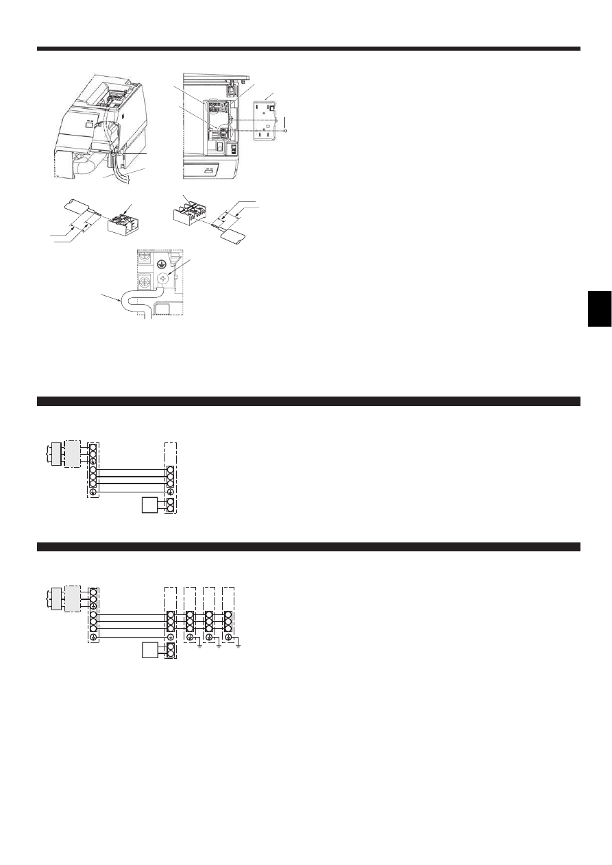
6.1. Indoor unit
! PKA-RP60, 71, 100KAL (Fig. 6-1)
Connection can be made without removing the front panel.
1. Open the front grille, remove the screw (1 piece), and remove the electrical
parts cover.
2. Securely connect each wire to the terminal board.
* In consideration of servicing, provide extra length for each of the wires.
* Take care when using strand wires, because beards may cause the wiring to
short out.
3. Install the parts that were removed back to their original condition.
4. Fasten each of the wires with the clamp under the electrical parts box.
A Electrical box cover
B Fixing screw
C Clamp
D Ground wire connection portion
E Wired remote control terminal board: (option) 1 and 2, do not have polarity
F Indoor/outdoor connection terminal board: S1, S2, and S3, have polarity
G Lead
H Terminal screw
I Ground wire: Connect the ground wire in the direction illustrated in the diagram.
J Wired remote control cord
K Indoor/outdoor connection cord
! PKA-RP60, 71, 100KAL
Fig. 6-1
H
H
12mm
55mm
D
12mm
55mm
E
F
K
J
C
J
K
D
F
E
A
B
S3
I
G
6.1.1. Indoor unit power supplied from outdoor unit
The following connection patterns are available.
The outdoor unit power supply patterns vary on models.
S1
S2
L
N
1
2
S1
S2
S3
S3
A
B
C
D
E
F
G
S1
S2
L
N
1
2
S1
S2
S3
S1
S2
S3
S3
S1
S2
S3
S1
S2
S3
A
B
C
D
E
F
H
H
H
G
G
G
G
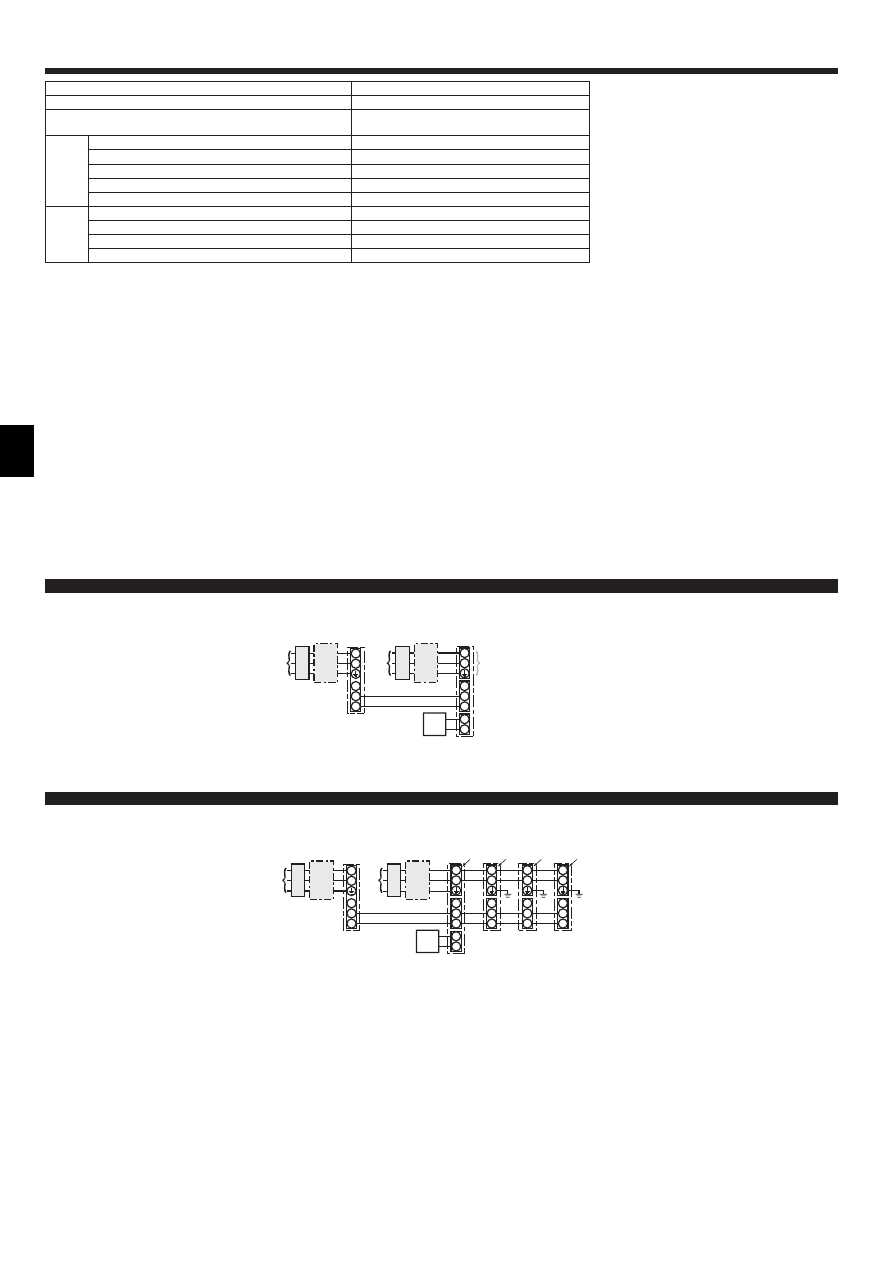
Simultaneous twin/triple/four system
* Affix a label A that is included with the manuals near each wiring diagram for the indoor and outdoor units.
A Outdoor unit power supply
B Earth leakage breaker
C Wiring circuit breaker or isolating switch
D Outdoor unit
E Indoor/outdoor unit connecting cords
F Wired remote controller (option)
G Indoor unit
H Indoor unit earth
1:1 System
10
Indoor unit model
PKA-RP·KAL
Indoor unit power supply
–
Indoor unit input capacity
*1
Main power switch (Breaker)
–
Wiring
Wire No. × size
(mm
2
)
Indoor unit power supply
–
Indoor unit earth
1 × Min. 1.5
Indoor unit-Outdoor unit
*2
3 × 1.5 (Polar)
Indoor unit-Outdoor unit earth
*2
1 × Min. 1.5
Wired remote controller (option) Indoor unit
*3
2 × Min. 0.3
Circuit
rating
Indoor unit L-N
*4
–
Indoor unit-Outdoor unit S1-S2
*4
AC 230 V
Indoor unit-Outdoor unit S2-S3
*4
DC 24 V
Wired remote controller (option) Indoor unit
*4
DC 12 V
*1. A breaker with at least 3 mm contact separation in each pole shall be provided. Use non-fuse breaker (NF) or earth leakage breaker (NV).
*2. <For 25-140 outdoor unit application>
Max. 45 m
If 2.5 mm
2
used, Max. 50 m
If 2.5 mm
2
used and S3 separated, Max. 80 m
For PUHZ-RP100/125/140 YHA application, use shield wires. The shield part must be grounded with the indoor unit OR the outdoor unit, NOT with both.
<For 200/250 outdoor unit application>
Max. 18 m
If 2.5 mm
2
used, Max. 30 m
If 4 mm
2
used and S3 separated, Max. 50 m
If 6 mm
2
used and S3 separated, Max. 80 m
*3. Max. 500 m
*4. The figures are NOT always against the ground.
S3 terminal has DC 24 V against S2 terminal. However between S3 and S1, these terminals are not electrically insulataed by the transformer or other device.
Notes: 1. Wiring size must comply with the applicable local and national code.
2. Power supply cords and Indoor unit/Outdoor unit connecting cords shall not be lighter than polychloroprene sheathed flexible cord. (Design 245 IEC
57)
3. Install an earth longer than other cords.
6. Electrical work
6.1.2. Separate indoor unit/outdoor unit power supplies (For PUHZ application only)
The following connection patterns are available.
The outdoor unit power supply patterns vary on models.
* The optional wiring replacement kit is required.
S1
S2
L
N
1
2
L
N
S1
S2
S3
S3
A
C
B
D
J
E
B
C
F
G
H
S1
S2
L
N
1
2
L
N
S1
S2
S3
L
N
S1
S2
S3
L
N
S1
S2
S3
L
N
S1
S2
S3
S3
A
B
C
D
E
J
B
C
F
H
G
G
G
G
H
H
H
K
K
K
* Affix a label B that is included with the manuals near each wiring diagram for the indoor and outdoor units.
A Outdoor unit power supply
B Earth leakage breaker
C Wiring circuit breaker or isolating switch
D Outdoor unit
E Indoor/outdoor unit connecting cords
F Wired remote controller (option)
G Indoor unit
H Option
J Indoor unit power supply
* The optional wiring replacement kits are required.
Simultaneous twin/triple/four system
* Affix a label B that is included with the manuals near each wiring diagram for the indoor and outdoor units.
A Outdoor unit power supply
B Earth leakage breaker
C Wiring circuit breaker or isolating switch
D Outdoor unit
E Indoor/outdoor unit connecting cords
F Wired remote controller (option)
G Indoor unit
H Option
J Indoor unit power supply
K Indoor unit earth
1:1 System
11
S1
S2
S3
L
N
BLUE
BLUE
YELLO
W
YELLO
W
CN01
CN01
BLACK
CN01
BLACK
S1
S2
S3
L
N
YELLO
W
BLUE
BLUE
YELLO
W
CN01
Indoor unit model
PKA-RP·KAL
Indoor unit power supply
~/N (single), 50 Hz, 230 V
Indoor unit input capacity
*1
Main power switch (Breaker)
16 A
Wiring
Wire No. × size
(mm
2
)
Indoor unit power supply & earth
3 × Min. 1.5
Indoor unit earth
1 × Min. 1.5
Indoor unit-Outdoor unit
*2
2 × Min. 0.3
Indoor unit-Outdoor unit earth
–
Wired remote controller (option) Indoor unit
*3
2 × Min. 0.3 (Non-polar)
Circuit
rating
Indoor unit L-N
*4
AC 230 V
Indoor unit-Outdoor unit S1-S2
*4
–
Indoor unit-Outdoor unit S2-S3
*4
DC 24 V
Wired remote controller (option) Indoor unit
*4
DC 12 V
*1. A breaker with at least 3 mm contact separation in each pole shall be provided. Use non-fuse breaker (NF) or earth leakage breaker (NV).
*2. Max. 120 m
For PUHZ-RP100/125/140 YHA application, use shield wires. The shield part must be grounded with the indoor unit OR the outdoor unit, NOT with both.
*3. Max. 500 m
*4. The figures are NOT always against the ground.
Notes: 1. Wiring size must comply with the applicable local and national code.
2. Power supply cords and indoor unit/outdoor unit connecting cords shall not be lighter than polychloroprene sheathed flexible cord. (Design 245 IEC
57)
3. Install an earth longer than other cables.
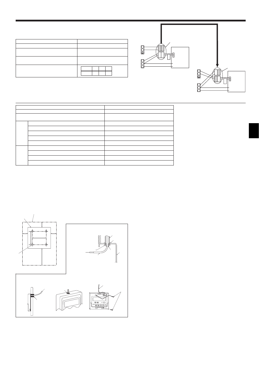
If the indoor and outdoor units have separate power supplies, refer to the table
at the below. If the optional wiring replacement kit is used, change the indoor unit
electrical box wiring refering to the figure in the right and the DIP switch settings of
the outdoor unit control board.
Indoor unit specifications
Indoor power supply terminal kit (option)
Required
Indoor unit electrical box connector
connection change
Required
Label affixed near each wiring diagram for
the indoor and outdoor units
Required
Outdoor unit DIP switch settings (when
using separate indoor unit/outdoor unit
power supplies only)
ON
OFF
1
2
(SW8)
3
* There are three types of labels (labels A, B, and C). Affix the appropriate labels to
the units according to the wiring method.
Connectors (connections when shipped
from the factory are for indoor unit power
supplied from outdoor unit)
Indoor unit power supplied from outdoor unit
(when shipped from factory)
If the indoor and
outdoor units have
separate power
supplies, change the
connections of the
connectors as shown
in the following
figure.
Connectors
Indoor unit
control board
Separate indoor unit/outdoor unit power
supplies
Indoor unit
control board
6. Electrical work
6.2. Remote controller
6.2.1. For wired remote controller
1) Installing procedures
(1) Select an installing position for the remote controller. (Fig. 6-2)
The temperature sensors are located on both remote controller and indoor unit.
! Procure the following parts locally:
Two piece switch box
Thin copper conduit tube
Lock nuts and bushings
A Remote controller profile
B Required clearances surrounding the remote controller
C Installation pitch
(2) Seal the service entrance for the remote controller cord with putty to prevent
possible invasion of dew drops, water, cockroaches or worms. (Fig. 6-3)
A For installation in the switch box:
B For direct installation on the wall select one of the following:
• Prepare a hole through the wall to pass the remote controller cord (in order to run
the remote controller cord from the back), then seal the hole with putty.
• Run the remote controller cord through the cut-out upper case, then seal the cut-
out notch with putty similarly as above.
B-1. To lead the remote controller cord from the back of the controller:
B-2. To run the remote controller cord through the upper portion:
(3) For direct installation on the wall
C Wall
D Conduit
E Lock nut
F Bushing
G Switch box
H Remote controller cord
I Seal with putty
J Wood screw
30
46
30
30
120
83.5
A
B
C
F
A
H
C
D
E
G
I
I
I
H
B
B-1.
B-2.
Fig. 6-3
Fig. 6-2
J
H
12
6. Electrical work
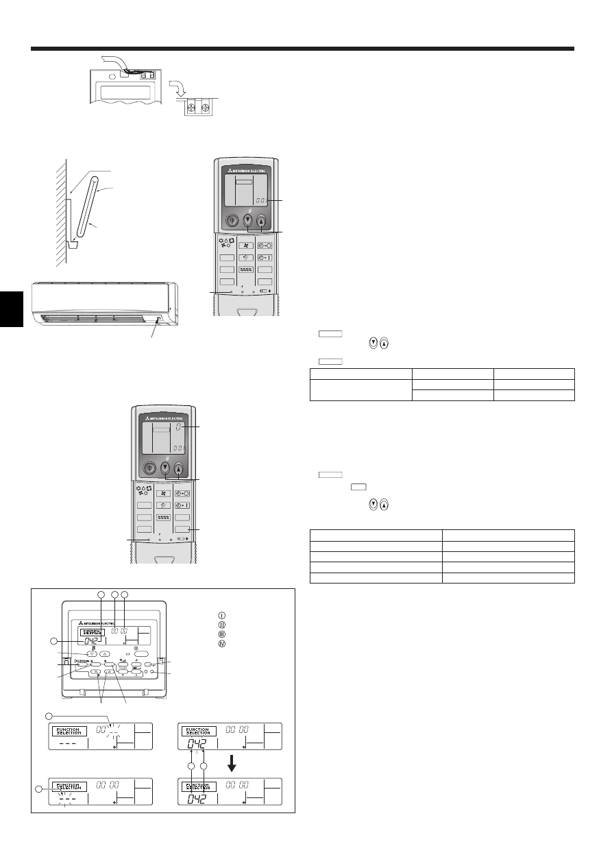
2) Connecting procedures (Fig. 6-4)
1 Connect the remote controller cord to the terminal block.
A To TB5 on the indoor unit
B TB6 (No polarity)
3) Two remote controllers setting
If two remote controllers are connected, set one to “Main” and the other to “Sub”.
For setting procedures, refer to “Function selection of remote controller” in the
operation manual for the indoor unit.
6.2.2. For wireless remote controller
1) Installation area
• Area in which the remote controller is not exposed to direct sunshine.
• Area in which there is no nearby heating source.
• Area in which the remote controller is not exposed to cold (or hot) winds.
• Area in which the remote controller can be operated easily.
• Area in which the remote controller is beyond the reach of children.
2) Installation method (Fig. 6-5)
1 Attach the remote controller holder to the desired location using two tapping
screws.
2 Place the lower end of the controller into the holder.
A Remote controller
B Wall
C Display panel
D Receiver
• The signal can travel up to approximately 7 meters (in a straight line) within 45
degrees to both right and left of the center line of the receiver.
3) Setting (Fig. 6-6)
1 Insert batteries.
2 Press the SET button with something sharp at the end.
MODEL SELECT
blinks and Model No. is lighted.
3 Press the temp
button to set the Model No.
4 Press the SET button with something sharp at the end.
MODEL SELECT
and Model No. are lighted for three seconds, then turned off.
Indoor
Outdoor
A Model No.
PKA (60, 71, 100)
PUH, PUHZ
002
PU
034
4) Assigning a remote controller to each unit (Fig. 6-7)
Each unit can be operated only by the assigned remote controller.
Make sure each pair of an indoor unit PC board and a remote controller is
assigned to the same pair No.
5) Wireless remote controller pair number setting operation
1 Press the SET button with something sharp at the end.
Start this operation from the status of remote controller display turned off.
MODEL SELECT
blinks and Model No. is lighted.
2 Press the
min
button twice continuously.
Pair No. “0” blinks.
3 Press the temp
button to set the pair number you want to set.
4 Press the SET button with something sharp at the end.
Set pair number is lighted for three seconds then turned off.
A Pair No. of wireless remote controller
Indoor PC board
0
Factory setting
1
Cut J41
2
Cut J42
3–9
Cut J41, J42
6.3. Function settings
6.3.1 Function setting on the unit (Selecting the unit functions)
1) For wired remote controller (Fig. 6-8)
Changing the power voltage setting
• Be sure to change the power voltage setting depending on the voltage used.
1 Go to the function setting mode.
Switch OFF the remote controller.
Press the A and B buttons simultaneously and hold them for at least 2
seconds. FUNCTION will start to flash.
2 Use the C button to set the refrigerant address (III) to 00.
3 Press D and [--] will start to flash in the unit number (IV) display.
4 Use the C button to set the unit number (IV) to 00.
5 Press the E MODE button to designate the refrigerant address/unit number. [--]
will flash in the mode number (I) display momentarily.
6 Press the F buttons to set the mode number (I) to 04.
7 Press the G button and the current set setting number (II) will flash.
Use the F button to switch the setting number in response to the power supply
voltage to be used.
Power supply voltage
240 V
: setting number = 1
220 V, 230 V : setting number = 2
8 Press the MODE button E and mode and the setting number (I) and (II) will
change to being on constantly and the contents of the setting can be confirmed.
9 Press the FILTER A and TEST RUN B buttons simultaneously for at least two
seconds. The function selection screen will disappear momentarily and the air
conditioner OFF display will appear.
A
AB
TB6
B
ON/OFF
TEMP
FAN
VANE
TEST RUN
AUTO STOP
AUTO START
h
min
LOUVER
MODE
CHECK
RESET
SET
CLOCK
MODEL SELECT
2,4
3
A
Fig. 6-5
Fig. 6-6
Fig. 6-4
B
1
C
A
2
D
PAR-21MAA
ON/OFF
FILTER
CHECK
OPERATION
CLEAR
TEST
TEMP.
MENU
BACK
DAY
MONITOR/SET
CLOCK
ON/OFF
A
B
D
C
G
E
F
II
III IV
I
IV
I
II
I
Fig. 6-7
Fig. 6-8
Mode number
Setting number
Refrigerant address
Unit number
ON/OFF
TEMP
FAN
VANE
TEST RUN
AUTO STOP
AUTO START
h
min
LOUVER
MODE
CHECK
RESET
SET
CLOCK
MODEL SELECT
1,4
3
A
2
13
6. Electrical work
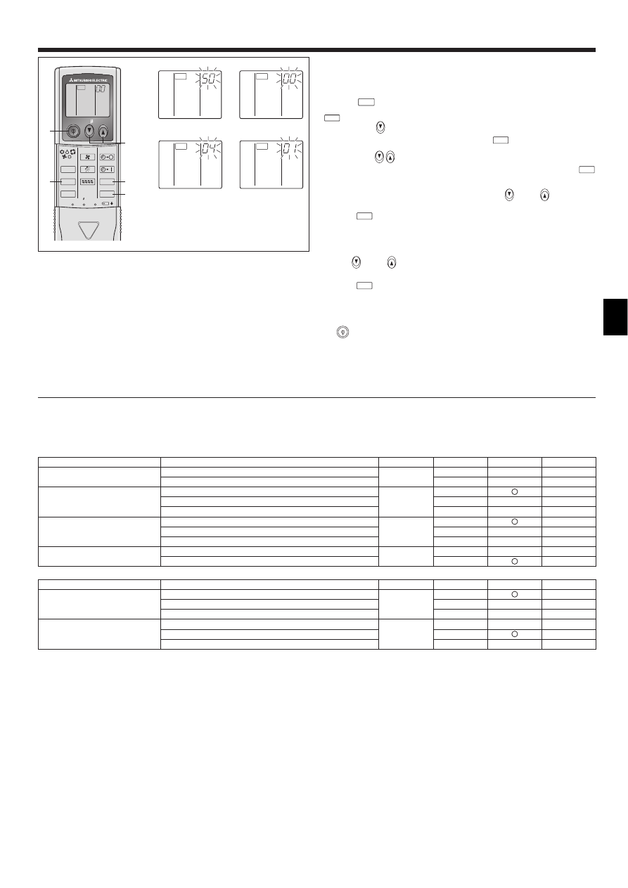
2) For wireless remote controller (Fig. 6-9)
Changing the power voltage setting
• Be sure to change the power voltage setting depending on the voltage used.
1 Go to the function select mode
Press the
CHECK
button F twice continuously.
(Start this operation from the status of remote controller display turned off.)
CHECK
is lighted and “00” blinks.
Press the temp
button C once to set “50”. Direct the wireless remote controller
toward the receiver of the indoor unit and press the
h
button A.
2 Setting the unit number
Press the temp
button C and D to set the unit number “00”. Direct the
wireless remote controller toward the receiver of the indoor unit and press the
min
button B.
3 Selecting a mode
Enter 04 to change the power voltage setting using the
C and
D buttons.
Direct the wireless remote controller toward the receiver of the indoor unit and
press the
h
button A.
Current setting number:
1 = 1 beep (one second)
2 = 2 beeps (one second each)
3 = 3 beeps (one second each)
4 Selecting the setting number
Use the
C and
D buttons to change the power voltage setting to 01 (240
V). Direct the wireless remote controller toward the sensor of the indoor unit and
press the
h
button A.
5 To select multiple functions continuously
Repeat steps 3 and 4 to change multiple function settings continuously.
6 Complete function selection
Direct the wireless remote controller toward the sensor of the indoor unit and press
the
button E.
Note:
Whenever changes are made to the function settings after installation or
maintenance, be sure to record the changes with a mark in the “Setting”
column of the Function table.
3
CHECK
4
CHECK
ON/OFF
TEMP
FAN
VANE
TEST RUN
AUTO STOP
AUTO START
h
min
LOUVER
MODE
CHECK
RESET
SET
CLOCK
CHECK
E
C,D
F
A
B
Fig. 6-9
2
CHECK
CHECK
1
6.3.2 Function setting on the remote controller
Refer to the indoor unit operation manual.
Function table
Select unit number 00
Mode
Settings
Mode no.
Setting no.
Initial setting
setting
Power failure automatic recovery
Not available
01
1
*2
Available
*1
2
*2
Indoor temperature detecting
Indoor unit operating average
02
1
Set by indoor unit’s remote controller
2
Remote controller’s internal sensor
3
LOSSNAY connectivity
Not Supported
03
1
Supported (indoor unit is not equipped with outdoor-air inlet)
2
Supported (indoor unit is equipped with outdoor-air inlet)
3
Power voltage
240 V
04
1
220 V, 230 V
2
Select unit numbers 01 to 03 or all units (AL [wired remote controller]/07 [wireless remote controller])
Mode
Settings
Mode no.
Setting no.
Initial setting
setting
Filter sign
100Hr
07
1
2500Hr
2
No filter sign indicator
3
Fan speed
Silent
08
1
Standard
2
High ceiling
3
–
*1 When the power supply returns, the air conditioner will start 3 minutes later.
*2 Power failure automatic recovery initial setting depends on the connecting outdoor unit.
14
7. Test run
7.1. Before test run
! After completing installation and the wiring and piping of the indoor and
outdoor units, check for refrigerant leakage, looseness in the power
supply or control wiring, wrong polarity, and no disconnection of one
phase in the supply.
! Use a 500-volt megohmmeter to check that the resistance between the
power supply terminals and ground is at least 1.0 M
!.
! Do not carry out this test on the control wiring (low voltage circuit)
terminals.
Warning:
Do not use the air conditioner if the insulation resistance is less than 1.0 M".
Insulation resistance
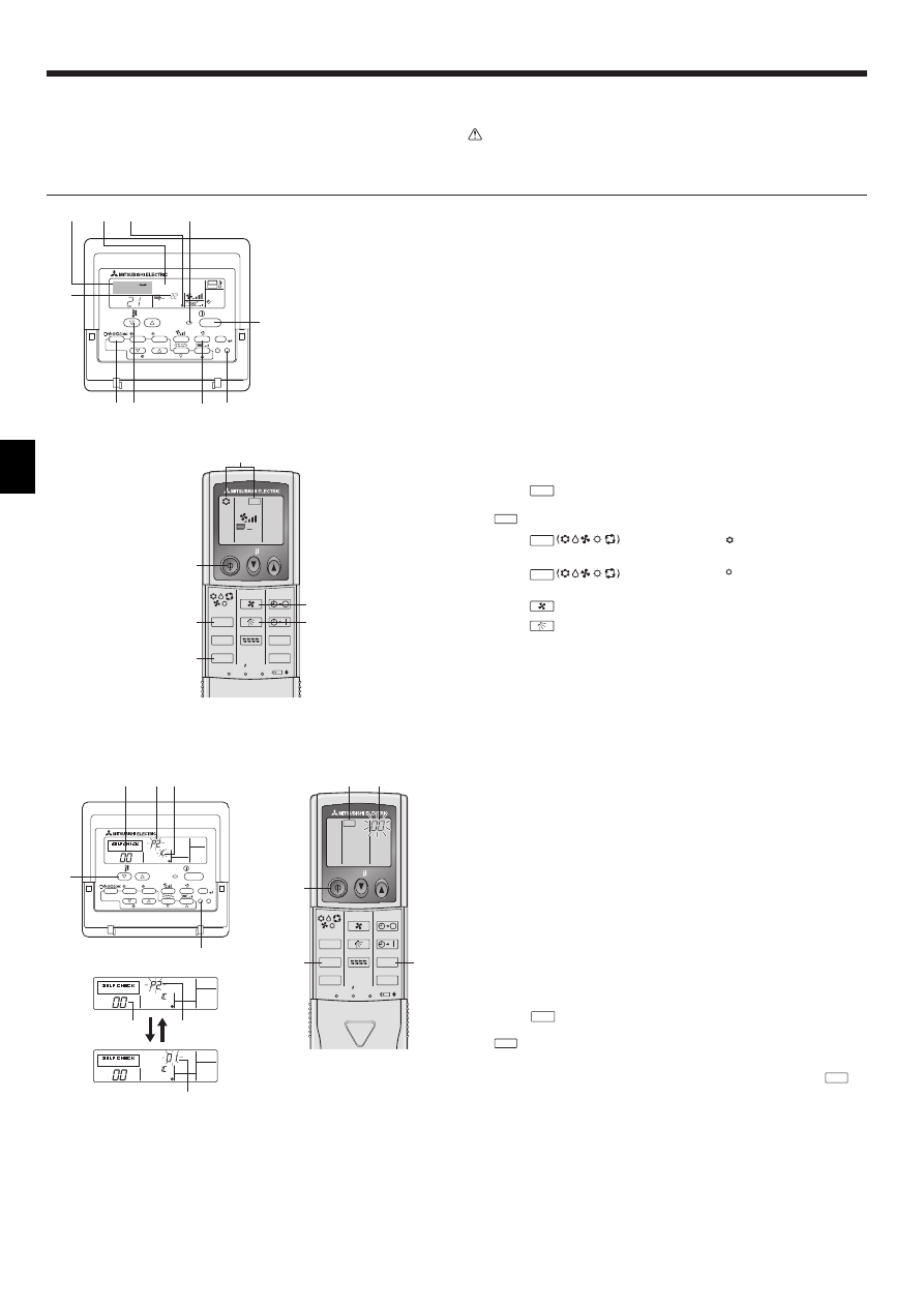
7.2. Test run
The following 3 methods are available.
7.2.1. Using wired remote controller (Fig. 7-1)
1 Turn on the power at least 12 hours before the test run.
2 Press the [TEST] button twice. $ “TEST RUN” liquid crystal display
3 Press the [Mode selection] button. $ Make sure that wind is blown out.
4 Press the [Mode selection] button and switch to the cooling (or heating) mode.
$ Make sure that cold (or warm) wind is blown out.
5 Press the [Fan speed] button. $ Make sure that the wind speed is switched.
6 Check operation of the outdoor unit fan.
7 Release test run by pressing the [ON/OFF] button. $ Stop
8 Register a telephone number.
The telephone number of the repair shop, sales office, etc., to contact if an
error occurs can be registered in the remote controller. The telephone number
will be displayed when an error occurs. For registration procedures, refer to the
operation manual for the indoor unit.
7.2.2. Using wireless remote controller (Fig. 7-2)
1 Turn on the power to the unit at least 12 hours before the test run.
2 Press the
TEST RUN
button twice continuously.
(Start this operation from the status of remote controller display turned off.)
A TEST RUN and current operation mode are displayed.
3 Press the
MODE
button to activate
COOL
mode, then check whether
cool air is blown out from the unit.
4 Press the
MODE
button to activate
HEAT
mode, then check whether
warm air is blown out from the unit.
5 Press the
FAN
button and check whether fan speed changes.
6 Press the
VANE
button and check whether the auto vane operates properly.
7 Press the ON/OFF button to stop the test run.
Note:
• Point the remote controller towards the indoor unit receiver while
following steps 2 to 7.
• It is not possible to run the in FAN, DRY or AUTO mode.
7.2.3. Using SW4 in outdoor unit
Refer to the outdoor unit installation manual.
7.3. Self-check
7.3.1. Wired remote controller (Fig. 7-3)
1 Turn on the power.
2 Press the [CHECK] button twice.
3 Set refrigerant address with [TEMP] button if system control is used.
4 Press the [ON/OFF] button to stop the self-check.
A CHECK button
B Refrigerant address
C TEMP. button
D IC: Indoor unit
OC: Outdoor unit
E Check code
F Unit address
7.3.2. Wireless remote controller (Fig. 7-4)
1 Turn on the power.
2 Press the
CHECK
button twice.
(Start this operation from the status of remote controller display turned off.)
A CHECK begins to light.
B “00” begins to blink.
3 While pointing the remote controller toward the unit’s receiver, press the
h
button. The check code will be indicated by the number of times that the buzzer
sounds from the receiver section and the number of blinks of the operation lamp.
4 Press the ON/OFF button to stop the self-check.
ON/OFF
TEMP
FAN
VANE
TEST RUN
AUTO STOP
AUTO START
h
min
LOUVER
MODE
CHECK
RESET
SET
CLOCK
TEST RUN
5
7
A
3,4
2
6
Fig. 7-2
Fig. 7-1
°C
°C
SIMPLE
PAR-21MAA
ON/OFF
FILTER
CHECK
OPERATION
CLEAR
TEST
TEMP.
MENU
BACK
DAY
MONITOR/SET
CLOCK
ON/OFF
TEST RUN
COOL, HEAT
A
F
C
E
D
B
M
I
HG
A ON/OFF button
B Test run display
C Indoor temperature liquid
line temperature display
D ON/OFF lamp
E Power display
F Error code display
Test run remaining time
display
G Set temperature button
H Mode selection button
I Fan speed button
M TEST button
ON/OFF
TEMP
FAN
VANE
TEST RUN
AUTO STOP
AUTO START
h
min
LOUVER
MODE
CHECK
RESET
SET
CLOCK
CHECK
2
4
A
3
B
Fig. 7-4
Fig. 7-3
PAR-21MAA
ON/OFF
FILTER
CHECK
OPERATION
CLEAR
TEST
TEMP.
MENU
BACK
DAY
MONITOR/SET
CLOCK
ON/OFF
ERROR CODE
ERROR CODE
ERROR CODE
C
B
A
B
F
E
E D
15
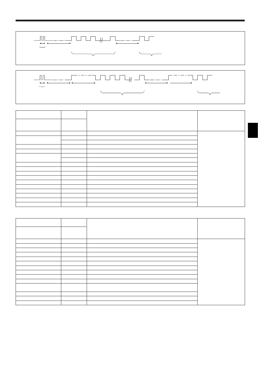
7. Test run
[Output pattern A] Errors detected by indoor unit
Wireless remote controller
Wired remote
controller
Symptom
Remark
Beeper sounds/OPERATION
INDICATOR lamp flashes
(Number of times)
Check code
1
P1
Inlet sensor error
2
P2
Pipe (TH2) sensor error
P9
Pipe (TH5) sensor error
3
E6, E7
Indoor/outdoor unit communication error
4
P4
Drain sensor error/Float switch connector open
5
P5
Drain pump error
PA
Forced compressor
6
P6
Freezing/Overheating safeguard operation
7
EE
Communication error between indoor and outdoor units
8
P8
Pipe temperature error
9
E4
Remote controller signal receiving error
10
–
–
11
–
–
12
Fb
Indoor unit control system error (memory error, etc.)
No sound
E0, E3
Wired remote controller transmission error
No sound
E1, E2
Wired remote controller control board error
No sound
– – – –
No corresponding
[Output pattern B] Errors detected by unit other than indoor unit (outdoor unit, etc.)
Wireless remote controller
Wired remote
controller
Symptom
Remark
Beeper sounds/OPERATION
INDICATOR lamp flashes
(Number of times)
Check code
1
E9
Indoor/outdoor unit communication error (Transmitting error) (Outdoor unit)
For details, check the LED
display of the outdoor controller
board.
2
UP
Compressor overcurrent interruption
3
U3, U4
Open/short of outdoor unit thermistors
4
UF
Compressor overcurrent interruption (When compressor locked)
5
U2
Abnormal high discharging temperature/49C worked/insufficient refrigerant
6
U1, Ud
Abnormal high pressure (63H worked)/Overheating safeguard operation
7
U5
Abnormal temperature of heat sink
8
U8
Outdoor unit fan safeguard stop
9
U6
Compressor overcurrent interruption/Abnormal of power module
10
U7
Abnormality of super heat due to low discharge temperature
11
U9, UH
Abnormality such as overvoltage or voltage shortage and abnormal
synchronous signal to main circuit/Current sensor error
12
–
–
13
–
–
14
Others
Other errors (Refer to the technical manual for the outdoor unit.)
*1 If the beeper does not sound again after the initial two beeps to confirm the self-check start signal was received and the OPERATION INDICATOR lamp does not come
on, there are no error records.
*2 If the beeper sounds three times continuously “beep, beep, beep (0.4 + 0.4 + 0.4 sec.)” after the initial two beeps to confirm the self-check start signal was received, the
specified refrigerant address is incorrect.
OPERATION
INDICATOR
lamp flash
pattern
Beep
Beep
Beep
Beep
Beep
Beep
Beep
Off
Approx. 2.5 sec.
On
Approx. 3 sec.
On
0.5 sec.
On
0.5 sec.
On
0.5 sec.
On
0.5 sec.
Off
Approx. 2.5 sec.
On
Approx. 3 sec.
On
0.5 sec.
On
0.5 sec.
· · · Repeated
Number of flashes/beeps in pattern indicates the check
code in the following table (i.e., n=5 for “P5”)
Number of flashes/beeps in pattern indicates
the check code in the following table
n
th
1
st
2
nd
3
rd
1
st
2
nd
Self-check
starts
(Start signal
received)
Beeper sounds
[Output pattern B]
OPERATION
INDICATOR
lamp flash
pattern
Beep
Beep
Beep
Beep
Beep
Beep
Beep
Off
Approx. 2.5 sec.
On
0.5 sec.
On
0.5 sec.
On
0.5 sec.
On
0.5 sec.
Off
Approx. 2.5 sec.
On
0.5 sec.
On
0.5 sec.
· · · Repeated
Number of flashes/beeps in pattern indicates the check
code in the following table (i.e., n=5 for “P5”)
Number of flashes/beeps in pattern indicates
the check code in the following table
n
th
1
st
2
nd
3
rd
1
st
2
nd
Self-check
starts
(Start signal
received)
Beeper sounds
• Refer to the following tables for details on the check codes. (Wireless remote controller)
[Output pattern A]
16
7. Test run
• On wireless remote controller
The continuous buzzer sounds from receiving section of indoor unit.
Blink of operation lamp
• On wired remote controller
Check code displayed in the LCD.
• If the unit cannot be operated properly after the above test run has been performed, refer to the following table to remove the cause.
Symptom
Cause
Wired remote controller
LED 1, 2 (PCB in outdoor unit)
PLEASE WAIT
For about 2
minutes following
power-on
After LED 1, 2 are lighted, LED 2 is turned off,
then only LED 1 is lighted. (Correct operation)
• For about 2 minutes following power-on, operation of
the remote controller is not possible due to system
start-up. (Correct operation)
PLEASE WAIT ! Error code
After about 2
minutes has
expired following
power-on
Only LED 1 is lighted. ! LED 1, 2 blink.
• Connector for the outdoor unit’s protection device is
not connected.
• Reverse or open phase wiring for the outdoor unit’s
power terminal block (L1, L2, L3)
Display messages do not appear even
when operation switch is turned ON
(operation lamp does not light up).
Only LED 1 is lighted. ! LED 1 blinks twice,
LED 2 blinks once.
• Incorrect wiring between indoor and outdoor units
(incorrect polarity of S1, S2, S3)
• Remote controller wire short
On the wireless remote controller with condition above, following phenomena takes place.
• No signals from the remote controller are accepted.
• OPE lamp is blinking.
• The buzzer makes a short pipng sound.
Note:
Operation is not possible for about 30 seconds after cancellation of function selection. (Correct operation)
For description of each LED (LED 1, 2, 3) provided on the indoor controller, refer to the following table.
LED 1 (power for microcomputer)
Indicates whether control power is supplied. Make sure that this LED is always lit.
LED 2 (power for remote controller)
Indicates whether power is supplied to the remote controller. This LED lights only in the case of the
indoor unit which is connected to the outdoor unit refrigerant address “0”.
LED 3 (communication between indoor and outdoor units)
Indicates state of communication between the indoor and outdoor units. Make sure that this LED
is always blinking.
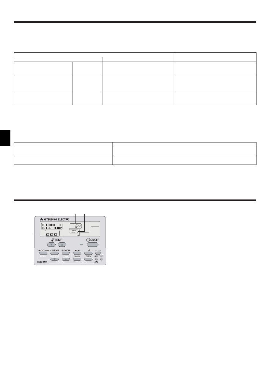
8. Easy maintenance function (Option)
By using the maintenance mode, you can display many types of maintenance data
on the remote controller such as the heat exchanger temperature and compressor
current consumption for the indoor and outdoor units.
This function can be used whether the air conditioner is operating or not.
During air conditioner operation, data can be checked during either normal
operation or maintenance mode stable operation.
* This function cannot be used during the test run.
* The availability of this function depends on the connecting outdoor unit. Refer to
the brochures.
D
A
C
B
Display example (Comp discharge temperature 64°C)
17
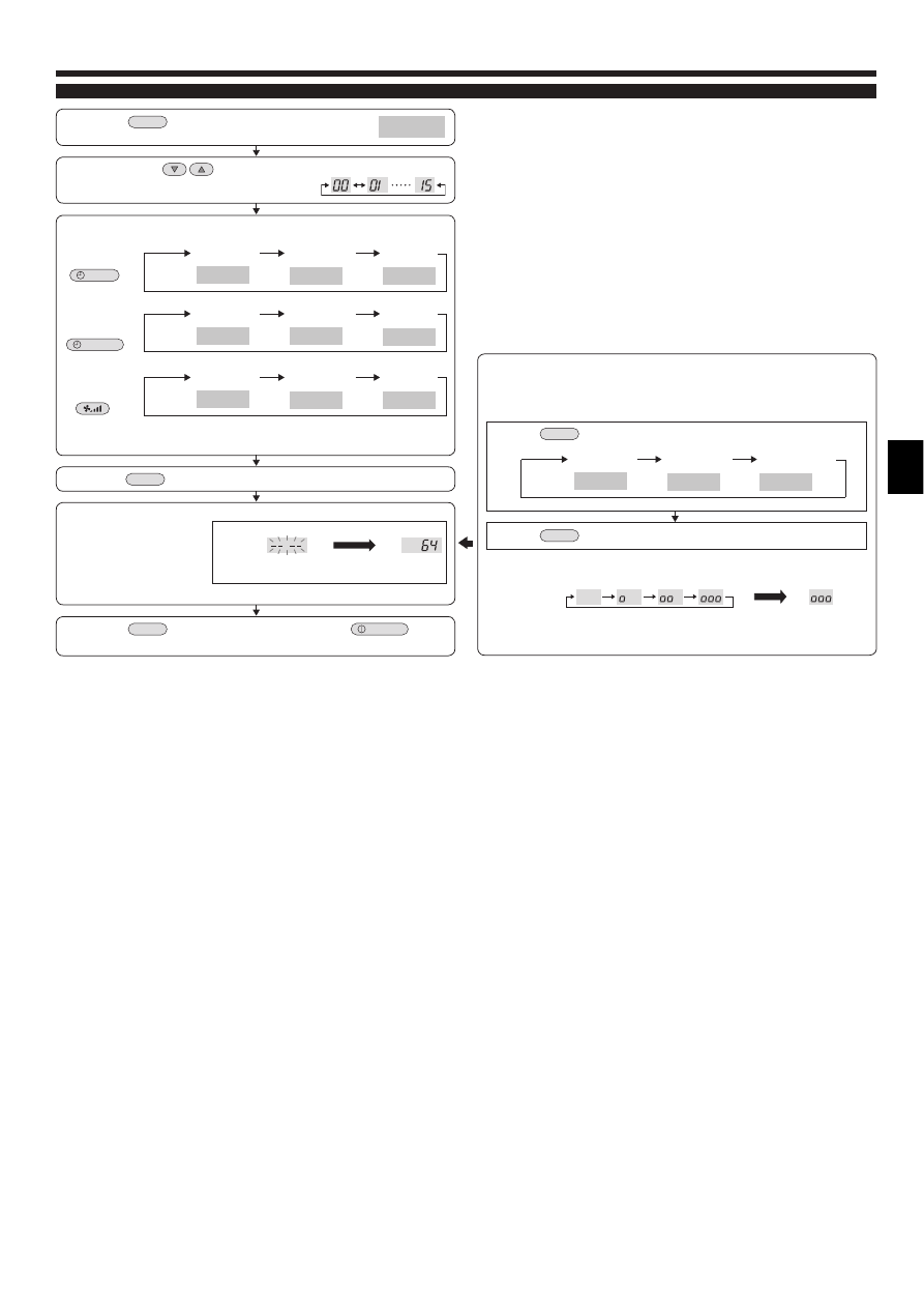
8. Easy maintenance function (Option)
Maintenance mode operation procedures
(1) Press the
TEST
button for three seconds to
activate the maintenance mode.
(2) Press the TEMP.
buttons to set the refrigerant address.
MAINTENANCE
(3) Select the data you want to display.
MENU
ON/OFF
Compressor
information
COMP ON
x10 HOURS
COMP ON
x100 TIMES
COMP ON
CURRENT (A)
Cumulative
operation time
ON/OFF
number
Operation
current
Display A
Display B
Display A
OUTDOOR UNIT
H·EXC. TEMP
OUTDOOR UNIT
OUTLET TEMP
OUTDOOR UNIT
OUTDOOR TEMP
Heat exchanger
temperature
Comp discharge
temperature
Outdoor ambient
temperature
Display A
Outdoor unit
information
INDOOR UNIT
INLET TEMP
INDOOR UNIT
H·EXC. TEMP
INDOOR UNIT
FILTER USE H
Indoor room
temperature
Heat exchanger
temperature
Filter operation
time
Display A
Indoor unit
information
* The filter operation time displayed is the number of hours the filter has been
used since the filter reset was performed.
(4) Press the
FILTER
button.
(5) The data is displayed in C.
(Airflow temperature display example)
Flashing
Waiting for
response
Approx.
10 sec.
64°C
* Repeat steps (2) to (5) to check another date.
(6) Press the
TEST
button for three seconds or press the
ON/OFF
button
to deactivate the maintenance mode.
Stable operation
Using the maintenance mode, the operation frequency can be fixed and the
operation can be stabilized. If the air conditioner is stopped, use the following
procedure to start this operation.
COOL
STABLE MODE
HEAT
STABLE MODE
STABLE MODE
CANCEL
Stable cooling
operation
Stable heating
operation
Stable operation
cancellation
Display A
Press the
MODE
button to select the operation mode.
Press the
FILTER
button.
Waiting for stable
operation
Display D
Stable
operation
10-20 min.
* You can check the data using steps (3) to (5) of the maintenance mode
operation procedures while waiting for the stable operation.
Display C
Wyszukiwarka
Podobne podstrony:
IM PKA RP60 71 100FAL BG79U616H01 2005
IM PKA RP60 71 100FAL2 PKH P BG79U616H02 2006
IM PCA RP50 140KA RG79D451H01 Jul 2009
IM PUMY P100 125 140YHMB BG79U713H05 Jul 2009
IM PFAV P250 900VM E WT05474X02 Oct 2009
IM PKA RP35 50GAL BG79U615H01 2005
BWE0630A PartsList PAC YT40ANRA E Jul 2009
IM PAC SE51CRB WT03594X05 GB Aug 2009
IM PKFY P32 50VHM E RG79D439H03 Aug 2009
IM PEA RP200 500GA WT05126X03 Aug 2009
IM CMY Q100VBK WT05688X01 GB Aug 2009
IM PUHZ HRP71 100 125VHA2 YHA2 RG79D355H03 GB 01 2009
Biogasanlagen im EEG 2009
IM jednolity tekst 2009
2009 4 JUL New Concepts in Diagnostic Radiology
ZESPÓŁ SZKÓŁ PONADGIMNAZJALNYCH NR l IM, 12.PRACA W SZKOLE, ZSG NR 1 2008-2009
Materialy do seminarium IM 2009 10 czesc I
więcej podobnych podstron