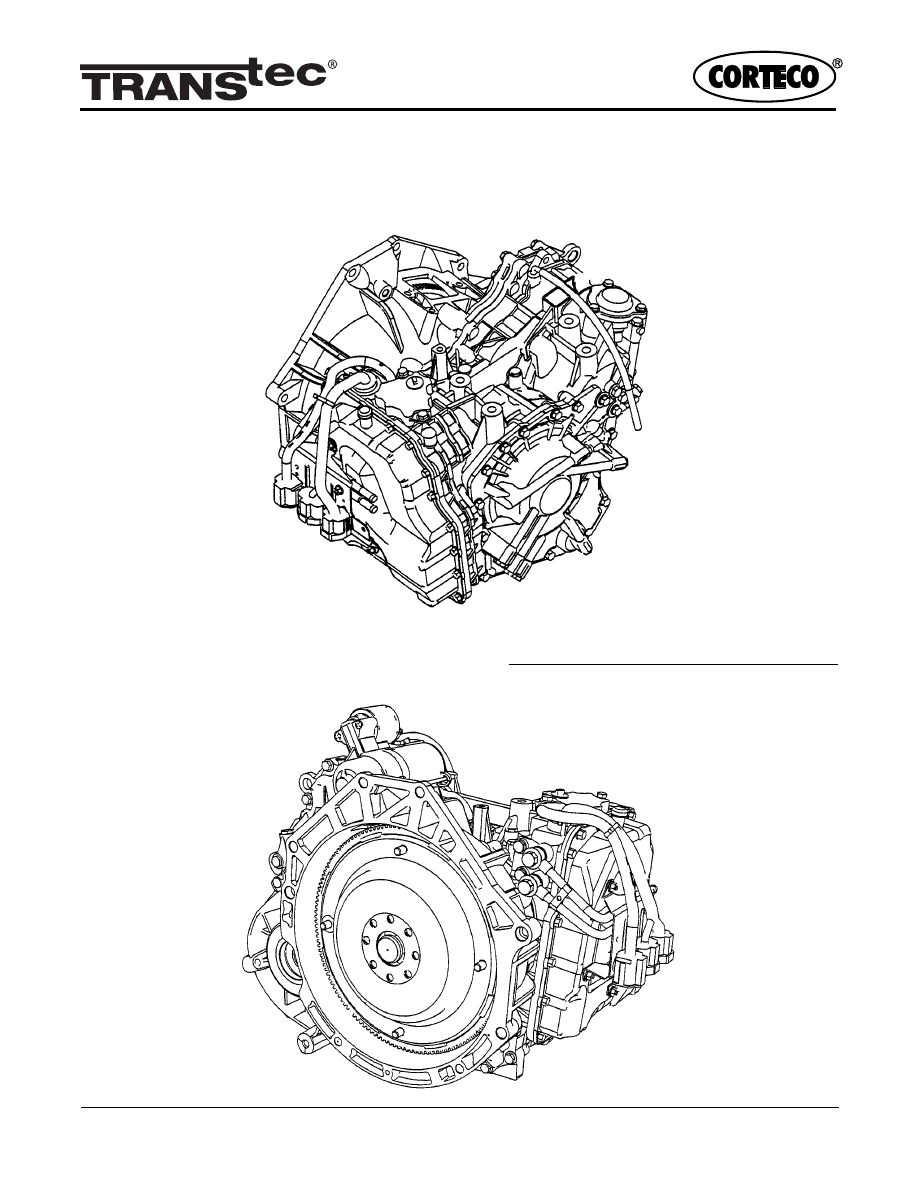
JF506E / 5F31J / 09A / JA5A-EL
FORD, MAZDA, VOLKSWAGEN, ROVER, SEAT
94231
MPV Van, Mondeo, Galaxy, X-type,
Freelander, 75 / 45, Sharan, Jetta / Golf, Alhambra
2
3
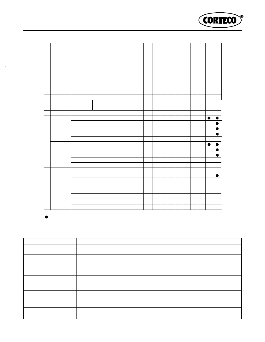
O
: Operating
: Transmits the torque only when driving
* : To prevent engine overspeed, inhibits downshift until the engine speed is reduced to the preset speed
P
-
-
O
Reverse
Yes
O
O
O
Reverse Inhibition Control No
O
O
N
-
-
-
O
First
No O
Second
No O
O
Third
No O
O
Fourth
No
O
O
Fifth
Yes
O
O
O
Fifth
No O
Fifth
No O
O
Fifth
No O
O
Yes
O
O
O
Fifth*
Yes
O
O
O
No O
O
Yes O
O
O
Fourth*
Yes
O
O
O
Fifth*
Yes
O
O
O
Yes O
O
O
Third*
Yes O
O
O
Fourth*
Yes
O
O
O
Fifth*
Yes
O
O
O
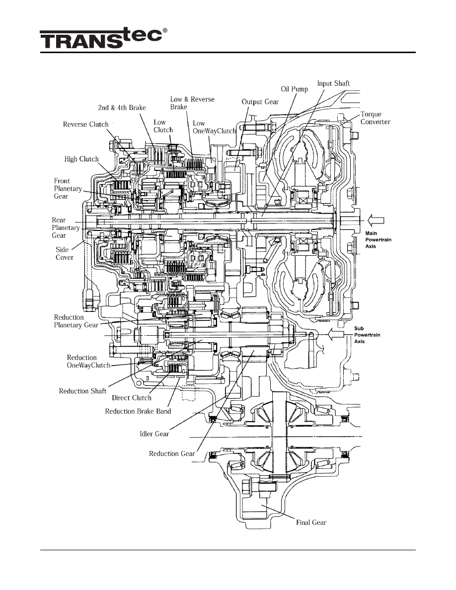
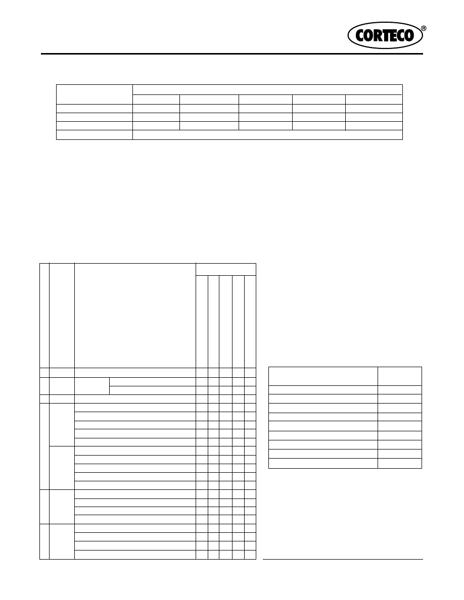
Low clutch
• Transmits rotation of low clutch drum to rear internal gear
• Operates in 1GR, 2GR, and 3GR position
2-4 brake
• Prevents rotation of front sun gear
• Operates in 2GR, 4GR, and 5GR position
High clutch
• Transmits rotation of high clutch drum to front planetary carrier
• Operates in 3GR, 4GR, and 5Gr position
Reverse clutch
• Transmits rotation of reverse clutch drum to front sun gear
• Operates when vehicle is reversing
Reduction brake
• Prevents rotation of direct clutch drum and prevents rottion of reduction sun gear
Low and reverse brake
• Prevents rotation of low clutch drum and front planetary carrier
Direct clutch
• Transmits rotation of reduction planetary carrier to reduction sun gear
• Operates in 5GR position
Low one-way clutch
• Locks clockwise rotation of front planetary carrier
Reduction one-way clutch
• Locks counterclockwise rotation of reduction sun gear
Component Function
Component description
Note: • All rotation are viewed from the side cover.
Gear Position
O/D
OFF
Switch
OFF
O/D
OFF
Switch
ON
-
R -
Engine braking ef
fect
Low clutch
2-4 brake
High clutch
Reverse clutch
Low and r
everse brake
Reduction brake
Dir
ect clutch
Low one-way clutch
Reduction one-way clutch
O. D. Switch
D
3
2
4
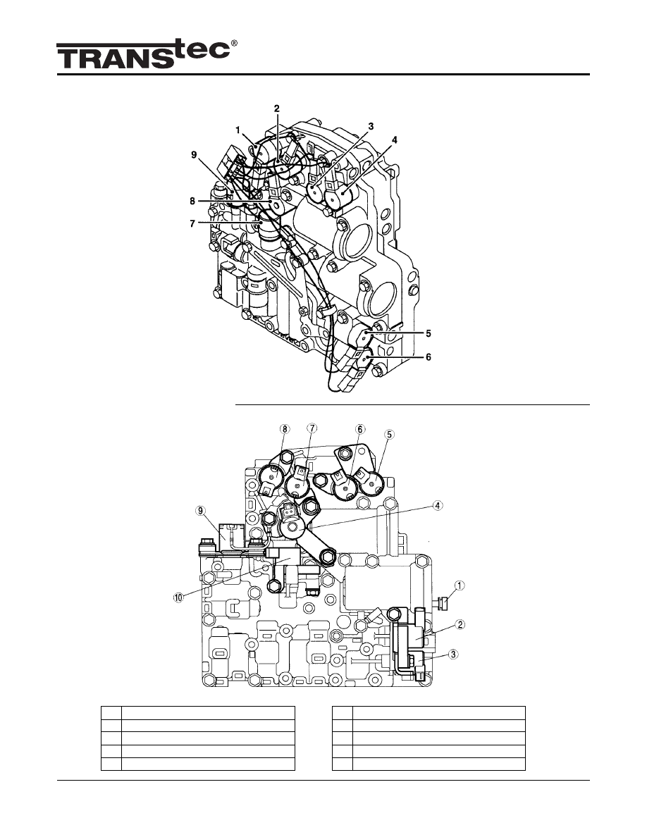
The On/Off Solenoid Valves Are:
• Shift Solenoid Valve A
• Shift Solenoid Valve B
• Shift Solenoid Valve C
• Low Clutch Timing Solenoid Valve
• Reduction Timing Solenoid Valve
• 2-4 Brake Timing Solenoid Valve
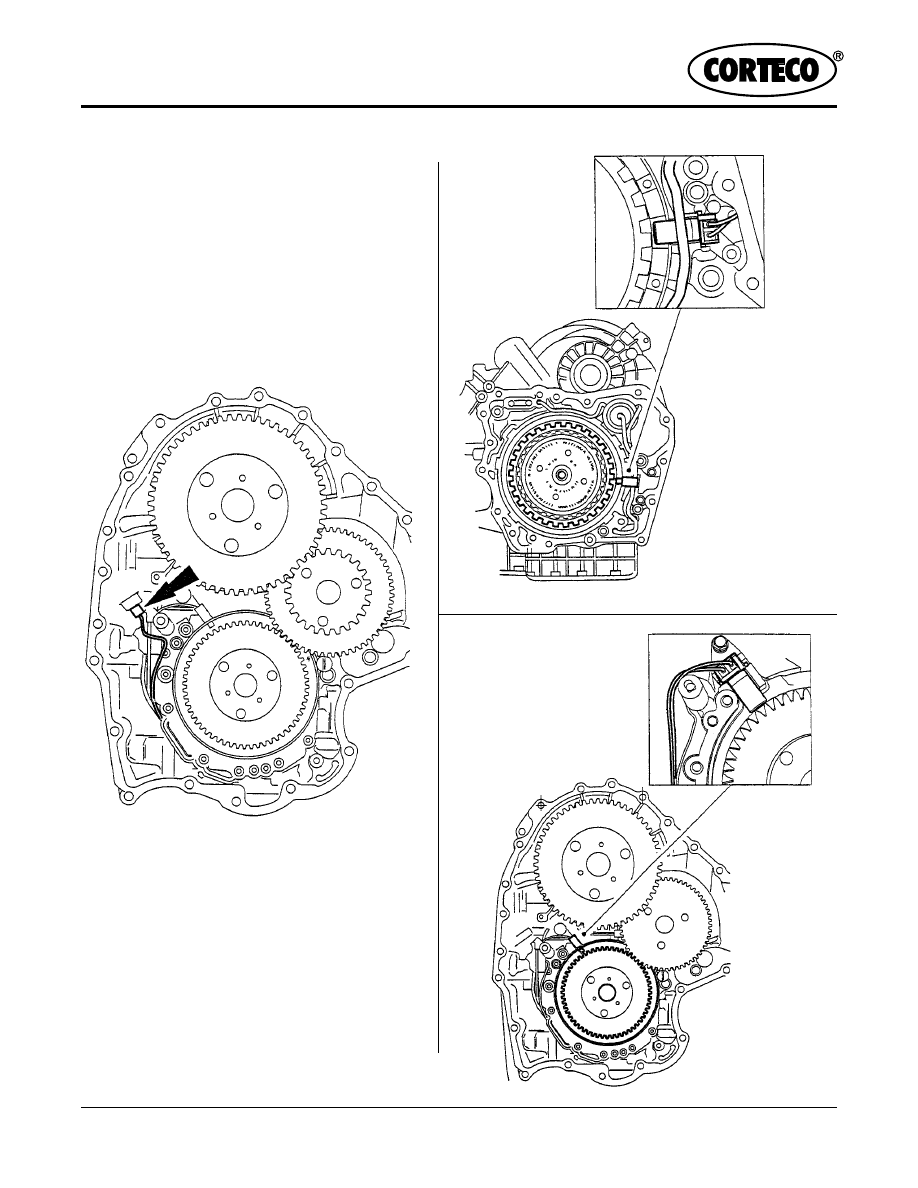
1 Manual valve
2 2-4 Brake Solenoid Valve
3 Neutral Shift Solenoid Valve
4 TCC Solenoid Valve
5 Shift Solenoid C
6 Shift Solenoid B
7 Reduction Timing Solenoid Valve
8 Shift Solenoid A
9 Pressure Control Solenoid
10 High Clutch Solenoid Valve
MAZDA
FORD / VW
1. Shift Solenoid Valve A
2. Reduction Timing Solenoid Valve
3. Shift Solenoid Valve B
4. Shift Solenoid Valve C
5. 2-4 Brake Duty Solenoid Valve
6. 2-4 Brake Timing Solenoid Valve
7. Low Clutch Timing Solenoid Valve
8. Lock-up Solenoid Valve
9. Line Pressure Duty Solenoid Valve
5
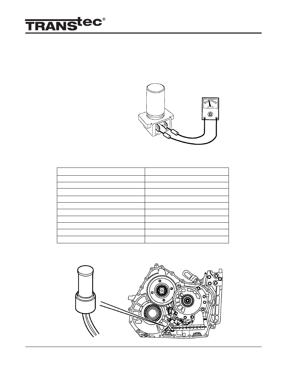
Resistance
(ohm)
2-4 Brake Solenoid Valve
2.6-3.2
TCC Solenoid Valve
12.0-13.2
High Clutch Solenoid Valve
2.6-3.2
Pressure Control Solenoid
2.6-3.2
Reduction Timing Solenoid Valve
14-18
Shift Solenoid C
14-18
Shift Solenoid B
14-18
Neutral Shift Solenoid Valve
14-18
Shift Solenoid A
14-18
Solenoid Valve
P
O O O
O O O
O O O
O
-
-
O O O
First
O O O
O
Second
O O
O
Third
O
O
Fourth
O
O
Fifth
O
O
O
Fifth
O O O
O
Fifth
O O
O
Fifth
O
O
O
Fifth*
O
O
O
O O
O
O
Fourth*
O
Fifth*
O
O
O
O O
Third*
O
Fourth*
O
Fifth*
O
O
O
O. D. Switch
Gear Position
Shift Solenoid A
Shift Solenoid B
Shift Solenoid C
Reduction Timing Solenoid
Neutral Shift Solenoid
D
3
2
O/D
OFF
Switch
OFF
O/D
OFF
Switch
ON
-
Mode
R
-
Solenoid Valve
MAZDA
The reduction timing solenoid valve, low clutch timing solenoid valve and 2-4 timing solenoid valve are utilised by
the EAT ECU to control the timing of the gear shift changes. These solenoid valves carry out four main functions:
• Shift timing control: For some shifts these three solenoid valves are used to assist line pressure control or 2-4
brake pressure control.
• Line pressure cut back: When the gearbox takes up the drive, there should be a high line pressure present. The
EAT ECU controls the low clutch timing solenoid valve which is related to the vehicle speed in order to switch
the fluid circuit of the line pressure to on or off therefore controlling cut back.
• Reverse inhibition: If the vehicle exceeds 6 mph (10 km/h) and Reverse (R) is selected, the EAT ECU switches
the low clutch timing solenoid valve on. This drains the gearbox fluid from the reverse clutch, therefore the clutch
will be unable to engage.
• Idle neutral: The EAT ECU uses the low clutch timing and reduction timing solenoid valves to engage idle neutral.
1st
2nd
3rd
4th
5th
A
X
O
X
X
O
B
O
O
O
X
X
C
O
X
X
O
O
X = Solenoid Valve Off; O - Solenoid Valve On
FORD/VW
Shift Solenoid Sequence
Shift Solenoid Valve
Reverse inhibition control
Reverse
N
ATF Temperature: 20
O
C (68
O
F)
6
Vehicle Speed (Output) Sensor
Intermediate Shaft Sensor
Input Speed Sensor
Resistance
(ATF temperature: 20
o
C (68
o
F)
513-627 ohms
Fluid Temperature Sensor
Resistance, k
Ω
-40 (-40)
54.90
-20 (-4)
16.70
0 (32)
6.02
20 (68)
2.50
40 (104)
1.16
60 (140)
0.59
80 (176)
0.33
100 (212)
0.19
120 (248)
0.12
140 (284)
0.08
Temperature,
o
C (
o
F)
Fluid Temperature Sensor Resistance Values
VSS
OSS
ISS
7
Intermediate Shaft
Speed Sensor
Selector Lever
Lock Solenoid
Output Shaft Speed
(OSS) Sensor
SOME OF THE INFORMATION IN THIS BOOKLET MAY HAVE BEEN PROVIDED
OR APPROVED BY THE AUTOMATIC TRANSMISSION SERVICE GROUP AND/OR
THE AUTOMATIC TRANSMISSION REBUILDERS ASSOCIATION. THE INFOR-
MATION CONTAINED HEREIN IS ACCURATE TO THE BEST OF OUR KNOWLEDGE.
WE ARE NOT RESPONSIBLE FOR ANY INACCURACIES OR WARRANTY CLAIMS
WHICH MAY RESULT FROM THE USE OF THIS INFORMATION.
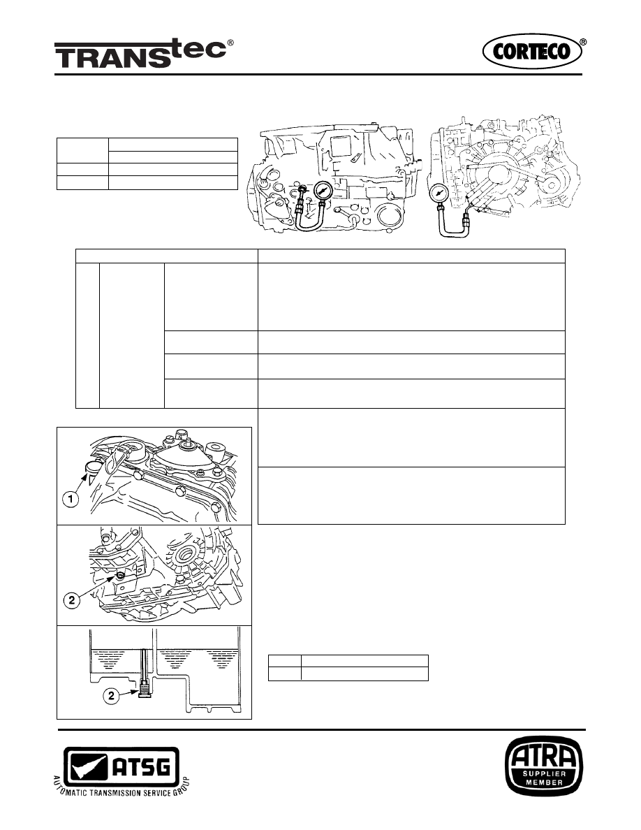
- Once the temperature has reached 35
o
C/95
o
F remove the
fluid level check plug. #2
- If transmission fluid flows out from the opening, wait until
the flow stops.
- If no transmission fluid flows out, top up with transmission
fluid through the filler neck #1 until fluid starts to escape
from the level check plug opening.
- Install the fluid level check plug.
Condition Possible Cause
Evaluation of Line Pressure Test
Low pressure in
all ranges
Below
Specification
Idle
Worn oil pump
Poor operation of each solenoid
Fluid leaking from oil strainer, oil pump, pressure regulator
valve, torque converter relief valve, and/or pressure relief valve
Pressure regulator valve or pilot valve sticking
Damaged pressure regulator valve spring or pilot valve spring
Fluid leaking from hydraulic circuit of low clutch
Fluid leaking from hydraulic circuit of low clutch and 2-4 brake
Fluid leaking from hydraulic circuit of reverse clutch
Fluid leaking from hydraulic circuit of low and reverse brake clutch
Throttle position sensor out of adjustment
TFT sensor malfunction
Poor operation of shift solenoid
Pilot valve sticking
Pressure reducing valve or plug sticking
Throttle position sensor out of adjustment
Pressure control solenoid malfunction
Poor operation of shift solenoid
Pilot valve sticking
Pressure reducing valve or plug sticking
D, 3, 2 Ranges
Low pressure in D
range only
Low pressure in
R position only
Low pressure in 3
and 2 ranges only
Fluid Level Check
1
Oil Filler Neck
2
Fluid Level Check Plug
Position/ Line Pressure (kPa(psi)
Range
Idle
D, 3
290-490 (42-71)
2, R
550-750 (80-109)
Wyszukiwarka
Podobne podstrony:
Analiza pracy Opis stanowiska pracy
opis techniczny
Opis taksacyjny
OPIS JAKO ĆWICZENIE W MÓWIENIU I PISANIU W ppt
2 Opis RMDid 21151 ppt
Bliższy opis obiektów Hauneb
opis techniczny
Opis zawodu Sprzedawca
opis 21 04
Opis silnikow krokowych id 3370 Nieznany
klimatex venta airwasher opis czesci
KRAŚNIK opis przyłącza
Opis skał
Opis zawodu Spec kontroli jakości
OPIS G
Opis baz danych zgodny z TERYT
opis zadania hydrologia
więcej podobnych podstron