PMG manual
page 1
June 2001
Contract R 7105
The Permanent Magnet Generator (PMG):
A manual for manufacturers and developers
By Hugh Piggott
Scoraig Wind Electric
In association with
ITDG-UK; ITDG Peru and ITDG South Asia

PMG manual
page 2
June 2001
Background
This research on small wind energy systems for battery charging is the result of a
collaborative effort involving numerous contributors.
The project was managed by Intermediate Technology (known as The Intermediate
Technology Development Group or ITDG) under a contract to the UK Department for
International Development.
The overall international project was co-ordinated by Dr Smail Khennas, Senior
Energy Specialist from ITDG, with support from Simon Dunnett. The field work in
Peru and Sri Lanka were respectively managed by Teo Sanchez and Rohan Senerath
with technical support from Sunith Fernando
Hugh Piggott, a technical consultant for the project, is the main author of this
manual on the Permanent Magnet Generator.
The views expressed in this report are those of the authors and do not necessarily
represent the views of the sponsoring organisations, the reviewers or the other
contributors.

PMG manual
page 3
June 2001
PMG construction manual
Contents
page
1. Introduction
4
2. List of materials and tools
8
3. Jigs and Moulds
10
4. Stator construction
25
5. Rotor construction
31
6. Assembly
36
7. Testing and connecting
41
8. Additional information
49
PMG manual
page 4
June 2001
Introduction
This manual describes how to build a 'permanent magnet generator' (PMG). We can
also call it an 'alternator', because it generates alternating current (AC). It will not
generate 'mains voltage' or 'utility power' AC. It generates low voltage, 'three phase'
AC, and then changes it into 'direct current' (DC) for charging a 12 volt battery.
What this PMG is made of
SPINE
REAR
ROTOR
SHAFT
FRONT
ROTOR
STATOR
12V
BATTERY
RECTIFIER
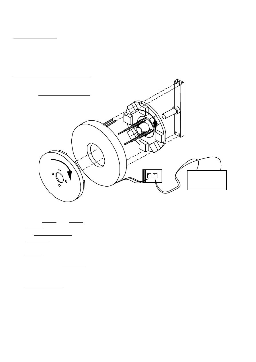
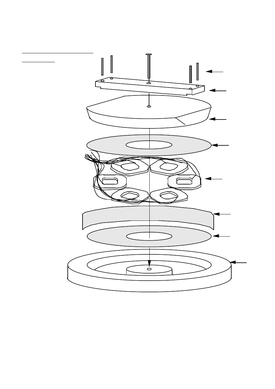
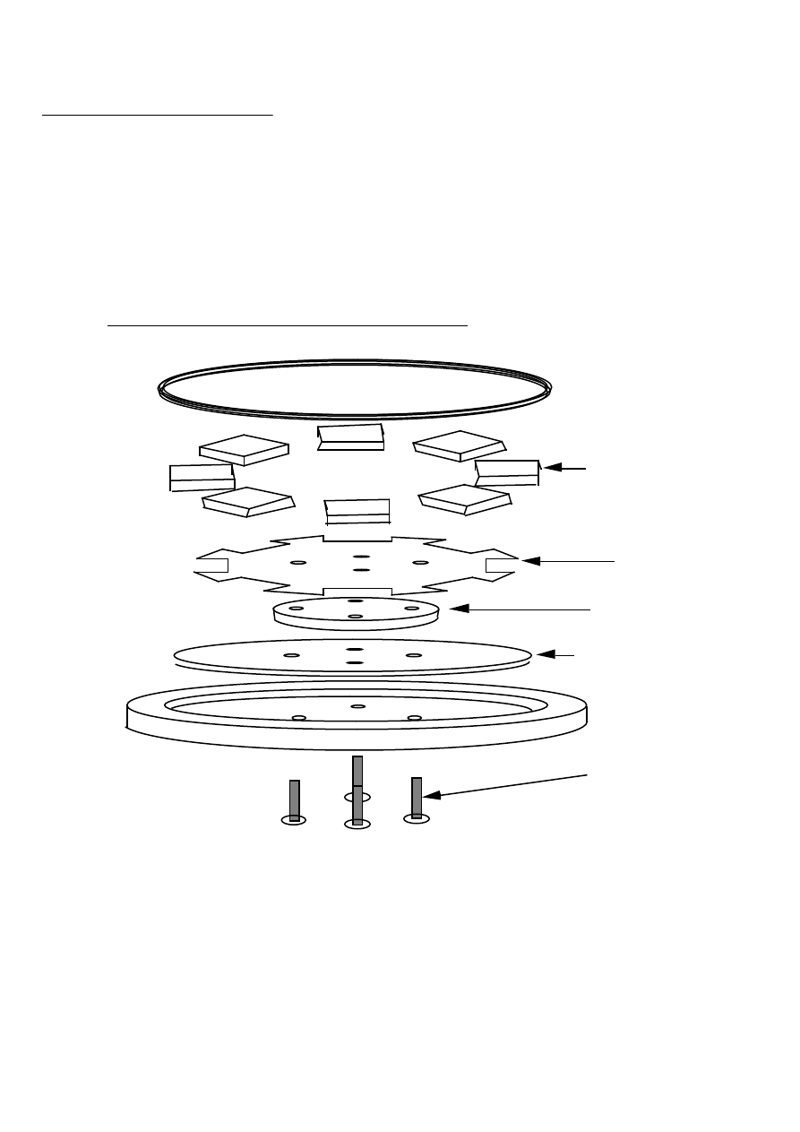
1. EXPLODED PMG
The PMG (see diagram 1) consists of:-
• A steel spine and shaft
.
• A stator containing coils of wire
• Two magnet rotors
• A rectifier
The stator contains six coils of copper wire, cast in fibreglass resin. This stator
casting is mounted onto the spine; it does not move. Wires from the coils take
electricity to the rectifier, which changes the AC to DC for charging the battery. The
rectifier is mounted on an aluminium 'heatsink' to keep it cool.
The magnet rotors are mounted on bearings, which turn on the shaft. The rear rotor
is behind the stator, and enclosed within it. The front one is on the outside, fixed to
the rear one by long studs which pass through a hole in the stator. The wind turbine
rotor blades will be mounted on the same studs. They will turn the magnet rotors,
and move the magnets past the coils. Magnetic flux passes from one rotor to the
other through the stator. This moving magnetic flux is what produces the electric
power.

PMG manual
page 5
June 2001
Building the PMG
This manual describes how to build the PMG. Read right through it before starting.
Section 2. is a list of materials and tools for the job.
Section 3 explains how to build the special tools (called jigs) and the moulds which
are needed. You can build more than one PMG with them. There are many possible
ways to make these jigs and moulds, but there is only room in this manual to
describe one way to do it.
Section 4 is about the stator. It describes how to wind the coils of enamelled
copper wire, and cast them in resin, using the jigs and moulds.
Section 5 shows how to build the magnet rotors, using magnet blocks and steel
disks, set in another resin casting.
Section 6 shows how to assemble the parts into a whole PMG. It explains how to
build the mechanical parts, how to balance the rotors, and what is required to
connect the wiring from the stator.
Section 7 is about testing the PMG. It contains procedures for checking that it is
correctly balanced and ready to use. It describes the options for connecting up the
electrical output. It also explains how to connect the PMG to the battery.
Section 8 contains additional information about the use of polyester resins, and
about using the PMG for hydro power.
What this PMG can do
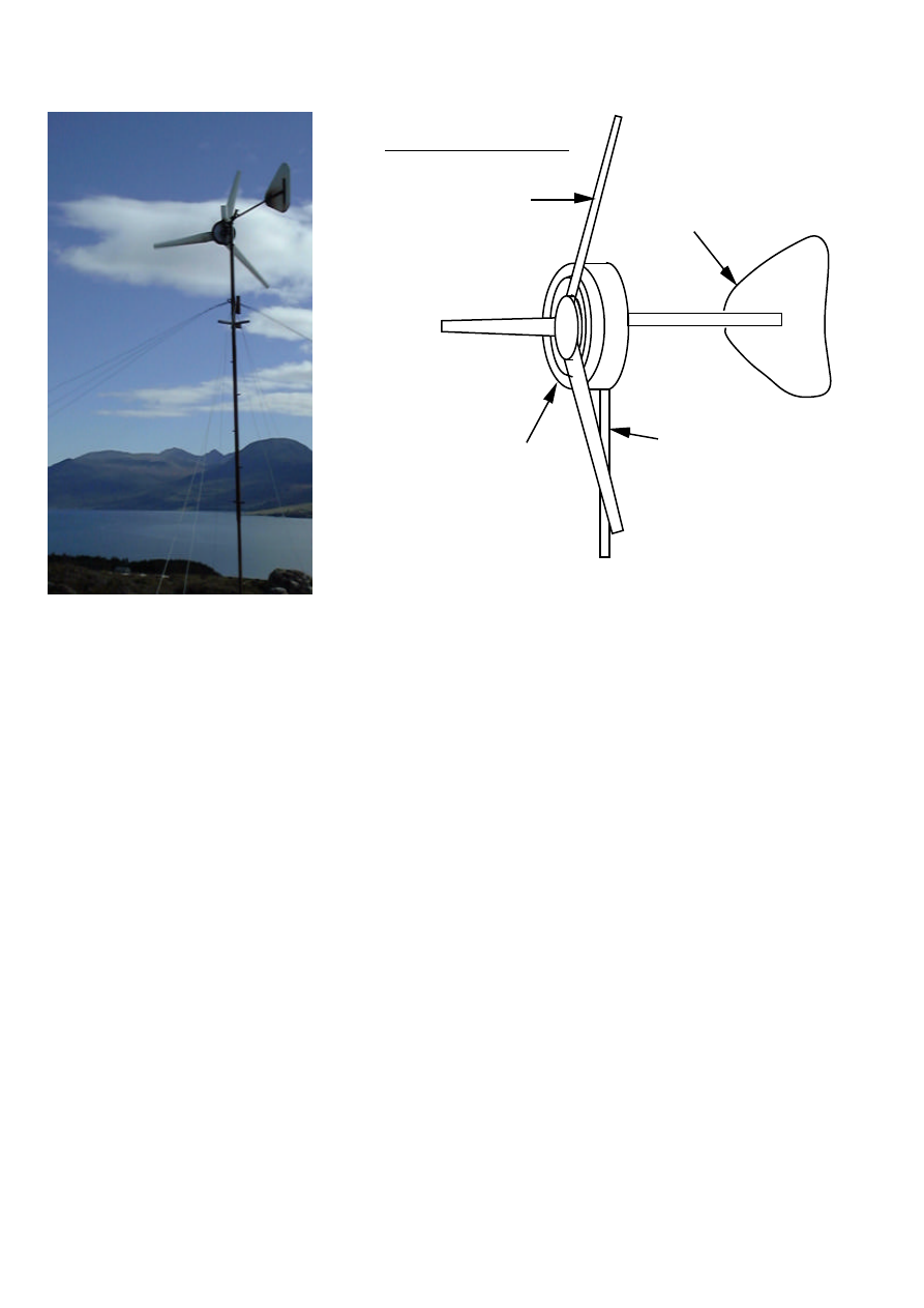
This PMG is made for small wind generators (see diagram 2). To build a complete
wind generator, you also need
• a tower : perhaps a steel pipe, supported with guy ropes,
• a 'yaw head' swivelling on the tower top,
• a tail, to keep it facing towards the wind,
• a set of blades, to turn it.
The spine of the PMG bolts on to the yaw head. The blade assembly fits on to the
front of the PMG. The yaw head and tail need to be so constructed that the wind
generator will turn from strong winds, to protect itself. (This manual does not
describe the blades, tower, or yaw head.)
PMG manual
page 6
June 2001
BLADES
ALTERNATOR
TAIL
TOWER
2. WIND TURBINE
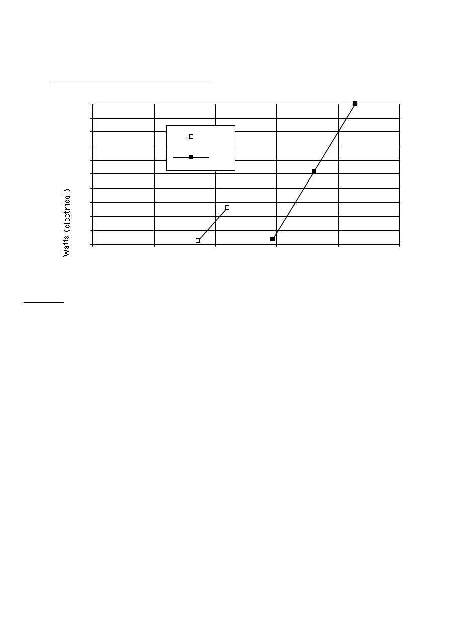
The PMG works at low rotational speed. The chart shows the power output of the
PMG, charging a 12 volt battery. At 420 rpm it generates 180 watts, which is 15
amps at 12 volts (15A x 12V = 180W).
At higher speed, the PMG can generate more power. But high currents cause the coils
to heat up, and so the efficiency gets worse as the output current gets higher. For
higher speed it is better to change the stator coils, either by using different size
wire, or by changing the way they are connected.
If the PMG is always used at higher speeds, it is better to use thicker wire, which
can carry more current without getting so hot. Using thicker wire means there are
fewer turns on the coils, which means that the PMG would not work at low speed.
To use the same PMG for both low and high speeds, it is possible to change the
connections. There are two ways to connect the stator wires to the rectifier. They
can be connected 'star' or 'delta'. See Section 7 for a detailed description of the star
and delta connections.
See diagram 3 for the graph of power vs. speed. Star begins to work at low speed
(170 rpm). Delta gives more power, but only at higher speed. Star is good in very low
windspeeds, and delta is better in higher winds.
A bigger version of this PMG would be able to give higher power at lower speed.
On test at Scoraig
PMG manual
page 7
June 2001
Speed in revs./minute (rpm)
0
20
40
60
80
100
120
140
160
180
200
0
100
200
300
400
500
star
delta
3.GRAPH OF POWER VS. SPEED
Caution
Take care when building and assembling the PMG so that the magnets cannot come
loose. This can happen under extreme circumstances. Loose magnets rubbing on the
stator can then destroy the PMG.
• Follow all the instructions for casting the magnet rotors - do not simply glue the
magnets to the steel disks.
• Do not hit the magnet rotors with hammers during assembly.
• Take care that there is at least 1mm gap clearance between the magnets and the
stator, on both sides. (For heavy duty, or high speed, use a larger gap.)
• Do not run the PMG at speeds faster than 800 rpm on a wind turbine. (When the
wind turbine yaws, large gyroscopic forces will flex the shaft, and the magnets
may touch.)
• Do not mount the rotor blade assembly directly onto the front magnet rotor disk,
at any point away from the studs. Mount it only onto the studs and nuts
themselves, which come through the disk.
• When mounting the PMG on the wind turbine yaw mount, keep the box section
'spine' of the PMG vertically upright, and not horizontally cross-wise.
PMG manual
page 8
June 2001
2. List of Materials and tools
Materials for PMGs
No.
per
PMG
size
Total wt.
grams
FIBREGLASS SUPPLIES
Polyester resin (premixed with accelerator)
2700
Catalyst (peroxide)
50
Talcum filler powder
1200
Fibreglass mat (1oz/sqfoot)
1 sq metre
300
Colouring pigment resin (if required)
50
plasticene or putty
STAINLESS STEEL
stainless steel wire
2mm x10metres
200
MAGNETS
Grade 3 ferrite magnet blocks (premagnetised)
16 20 x 50 x 50mm
4000
ELECTRICAL
Enamelled winding wire
14AWG or 1.7mm
(or 17AWG - see p.44)
3000
flexible wire (about 14AWG size)
same size x 6 metres
solder and sleeving for connections
1/2 inch masking tape
Bridge rectifiers
2 25A 200V single phase
Heatsink for rectifiers
250
STEEL
Box section tube ('RHS') for spine
1 380 x 50 x25 x 4mm
1100
Magnet disk (or octagonal) plates
2 6mm x
305mm Outer Diameter
6000
10mm threaded rod ('studding')
1000mm
500
10mm nuts
32
300
10mm washers
16
8mm threaded rod
400mm
125
8mm nuts
8
50
5mm nuts and bolts for rectifiers
2 5mm x 20mm
Shaft
25mm x 150mm
500
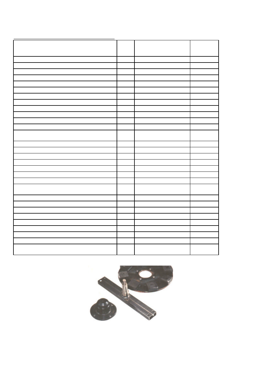
MECHANICAL
Bearing hub to fit shaft,
as described in Section 6
1
1250
Spine, shaft, hub and magnet rotor

PMG manual
page 9
June 2001
Materials for moulds and jigs
Composite floorboards (other ideas are possible) and wood glue
Sand paper, wax polish
(Polyurethane varnish, and PVA release agent, if available.)
Paint brushes, and thinners to clean them
13mm Plywood for jigs and formers and stator mould centre
Steel rod, or pipe, for coil winding machine
Small pieces of steel plate or thick sheet metal
Bolts (with nuts and washers)
diameter
length
For
2 with butterfly nuts
6mm
60mm
coil winder
4
10mm
25mm
balancing with jig
1
12mm
150mm
stator mould
Tools
Safety goggles, face mask, gloves, etc. as required
Workbench with vice
Welder
Angle grinder
Hacksaw, hammer, punch, chisel
Compasses, tape measure, angle gauge.
Spanners: 8, 10, 13, 17, 19mm : two of each.
Tap wrench and M10 taps for outer holes in magnet rotors.
Brass wire to gauge the heights of magnets
Pillar Drill Press
Drill bits 6,8,10,12mm
Holesaws 25mm, 65mm
Wood lathe, or a substitute as in Section 3
Chisel for wood lathe
Jigsaw to cut wood
Scales to weigh resin. Dispenser for catalyst, plastic buckets,
scissors.
Soldering iron, resin-cored solder, wire cutters, sharp knife.
PMG manual
page 10
June 2001
3. Jigs and Moulds
This section describes how to
make the jigs and moulds for
building a PMG. Once you have
made them, they can be used
again, to build more PMGs.
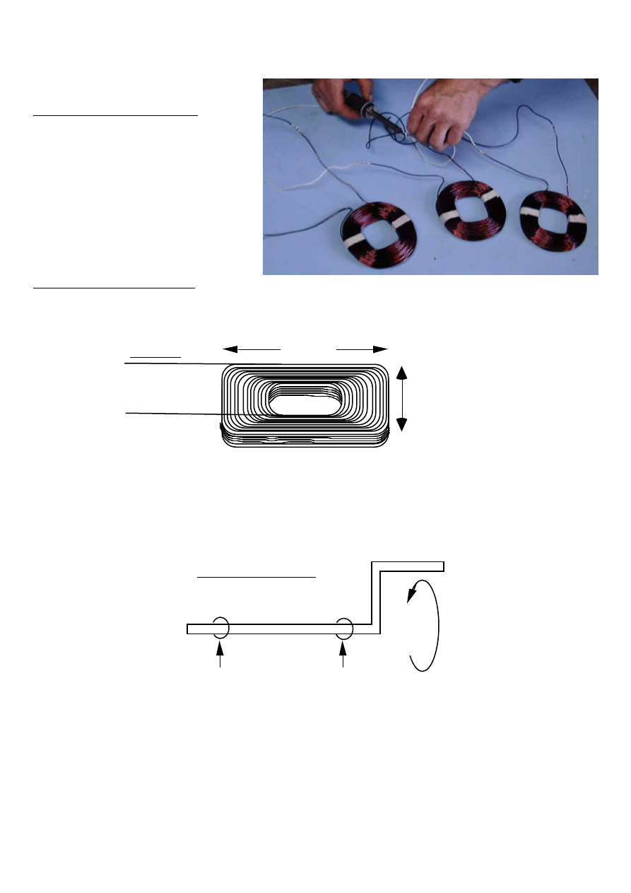
Coil winding machine
The PMG stator contains six coils of copper wire (see diagram 4).
4. COIL
100 TURNS OF
ENAMELLED
COPPER
WIRE
110mm
110mm
The coils will be wound on a plywood coil-former.
The former is mounted on the end of a crankshaft, between cheek pieces.
• Make a crankshaft, turned by a handle (see diagram 5).
SIMPLE
BEARINGS
HANDLE
5. CRANKSHAFT
Some coils for the stator

PMG manual
page 11
June 2001
• Cut a small flat steel plate 60 x 30 x 6 mm (suggested sizes) and fix it securely
or weld it to the end of the crankshaft as shown in diagram 6.
• Drill 2 holes, 6mm diameter and 40mm apart, centred on the shaft.
6. STEEL PLATE
60
30
• Cut out 3 pieces of 13mm plywood as in diagram 7.
50
20
50
125
20
125
125
20
7. COIL-FORMER AND CHEEK PIECES
The coil former is 50mm by 50mm by 13 thick. It has rounded corners. The two
'cheek pieces' are 125mm by 125mm. There are 20mm wide notches top and bottom
in each. The notches are for putting masking tape under the coil, so that it can be
taped up before removing it from the former.
• Stack the pieces with the notches in line (diagram 8), and drill holes for the
mounting bolts.
The holes are 6mm diameter and 40mm apart.
Use a drill press to drill the holes exactly square to the plywood.

PMG manual
page 12
June 2001
DRILL PRESS
STACK THE THREE PIECES
LIKE THIS:-
40mm
8. DRILLING THE 2 HOLES
• Pass two bolts through the holes in the flat plate, and bolt on the cheekpieces ,
with the coil-former between them. Use butterfly nuts if possible. (diagram 9.)
WINDING
WIRE
BUTTERFLY
NUTS
9. FITTING THE COIL FORMER AND CHEEK PIECES
PMG manual
page 13
June 2001
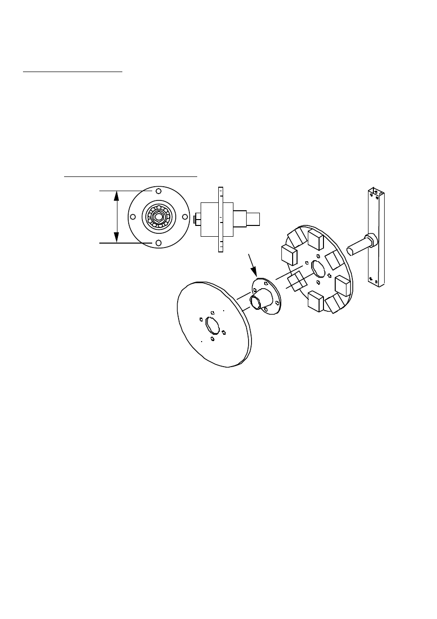
Jigs for the rotors
PCD jig for drilling holes
The magnet rotors are mounted on a bearing hub (see diagram 10). The hub has a
flange with holes in it. For example there may be four holes on a 102mm (4 inch)
'pitch circle diameter' (PCD). Or you may have some other arrangement. This will
depend on what kind of hub it is. Here we shall say 102mm PCD.
SPINE
REAR ROTOR
HUB
FRONT ROTOR
SHAFT
PCD
10. THE BEARING HUB PCD
The PCD jig will be used to drill holes in the rotors etc.
It will also be used to balance the rotors.
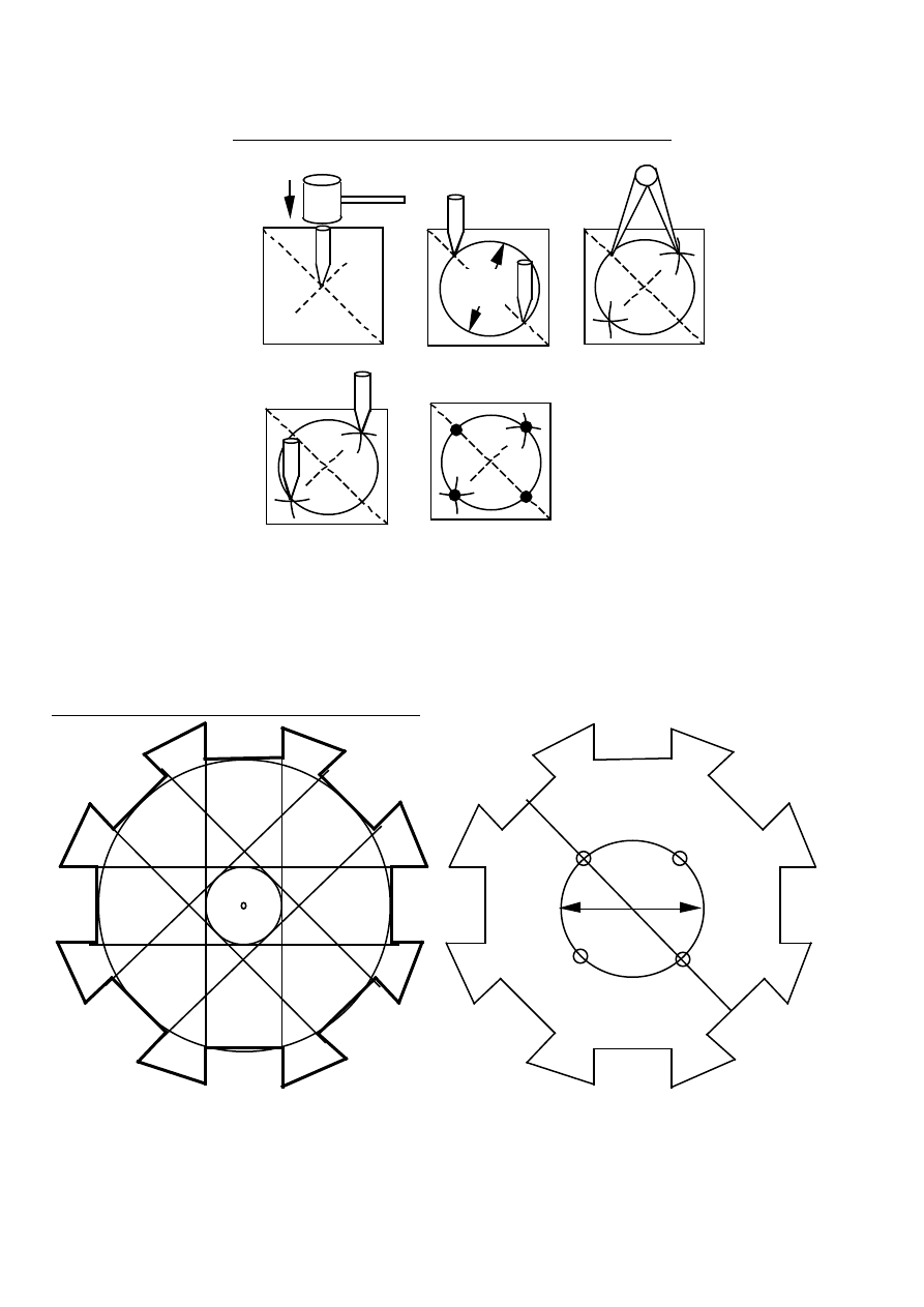
The holes must be marked and drilled very precisely. (See diagram 11.)
• Cut a square piece of steel plate 125mm by 125mm.
• Draw diagonal lines between the corners and mark the exact centre with a punch.
• Set your compasses at 51mm radius (or to suit whatever PCD). Draw a circle.
• The diameter of the circle is the PCD of the holes in the hub.
• Punch both places where one line meets the circle.
• Set your compasses at 72mm. Mark two points exactly this distance from the
first two, on the circle. (If you have a different PCD, this size would not be
72mm. Find the size by trial and error.)
• Drill four holes exactly 72 mm apart on the circle. Use a small drill first and
then a larger one.
PMG manual
page 14
June 2001
125
102
PCD
72
11. MARKING AND DRILLING THE PCD JIG
Magnet positioning jig (See diagram 12)
This jig is for putting the magnet blocks into the correct places on the steel disks.
Only one jig is needed. Make the jig from 250x250 mm plywood or aluminium sheet
(not steel).
12. THE MAGNET POSITIONING JIG
102
• Mark the centre of the workpiece.
• Draw three circles, with diameters 50mm, 102mm and 200mm, on this centre.
• Draw a pair of parallel straight lines, as tangents to the 50mm circle as shown.
PMG manual
page 15
June 2001
• Draw 3 more pairs of straight lines at 45 and 90 degree angles to the first pair.
• Using these lines, mark the magnet positions, and cut out the jig along the bold
lines as shown in the diagram.
• Draw a line connecting two opposite magnet centres.
• Place the PCD jig on top of the 102mm circle, aligned with the magnet centres,
and drill four holes to match the four holes in the steel disks.
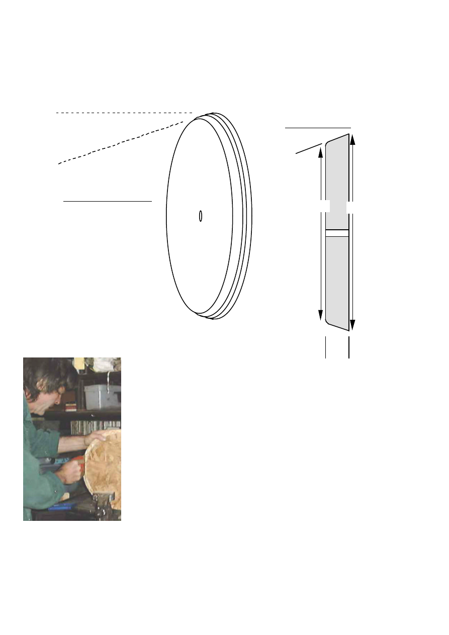
Making the moulds
Make moulds for the stator and rotor castings. They can be turned from wood or
aluminium. Another method is to make plaster or clay plugs on a wheel, like a pot.
The shape of the plug would be the shape of the outside of the stator. Then make a
fibreglass mould on the plug. The surface of each mould must be perfectly flat.
The moulds need to be strong and smooth. It is not easy to separate the stator
casting from the moulds. Hammer blows are usually needed.
It is a good idea to wind one coil (see section 4) before making the stator mould.
This coil should fit neatly in the mould.
Here is one way to make the moulds, from composite wooden floorboard sheets,
using wood-turning.
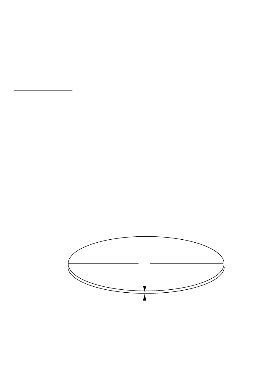
Stator Outer mould
• Cut out several disks of flooring sheet (see diagram 13), approximately 500mm
diameter.
500
20
13. DISKS
PMG manual
page 16
June 2001
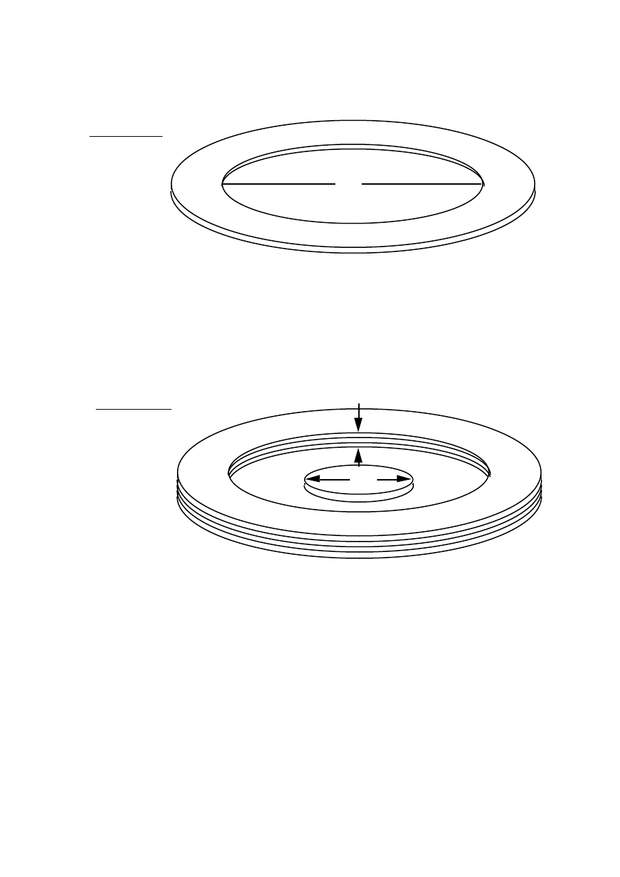
• Take all but one of the disks, and cut circular hole in each, 360mm diameter to
form rings (see diagram 14).
360
14. RINGS
• Draw a circle 360 mm diameter on the remaining disk
• Drill a 12 mm hole at the centre of this disk, to help with centring.
• Glue the rings on top of the remaining disk, to form a stack, with a hole 60mm
deep (diagram 15). Use plenty of glue at the insides of the rings.
• Cut out a small disk of 15 mm plywood, 140 mm in diameter, and drill a 12 mm
hole at its centre.
• Placing a 12 mm bolt through both holes, glue the small disk into the exact centre
of the hollow. Use plenty of glue at the edge of the disk.
15. STACK
140
60 DEEP
• Mount another piece of wood or board onto a lathe, a motor or the wheel hub of a
small vehicle (for example a 3-wheel taxi). This is a the faceplate (see diagram
16).
• Spin the faceplate and use a pencil to make a very small circle at the centre.
• Drill a 12mm hole precisely at this centre. Hold the drill parallel to the shaft.
• Screw the glued stack onto the faceplate, using a 12mm bolt to centre it. Use four
woodscrews through the disk and into the faceplate.
• Check that the face of the mould runs true. You can do this by holding a pencil
close to it while it spins. Where the pencil makes marks, the face is 'high'.
Loosen the screws and insert pieces of paper between the faceplate and the stack,
on the opposite side from the pencil marks. Tighten the screws and check again.

PMG manual
page 17
June 2001
MOTOR
STURDY
BENCH
TOOL REST
MOULD
CHISEL
FACEPLATE
16. TURNING A MOULD
Now it is possible to shape the mould with a chisel. Wear a mask over your mouth to
avoid inhaling the dust. Beware of loose clothing, which may become caught in the
rotating mould.
Turning a stator mould on an electric motor
PMG manual
page 18
June 2001
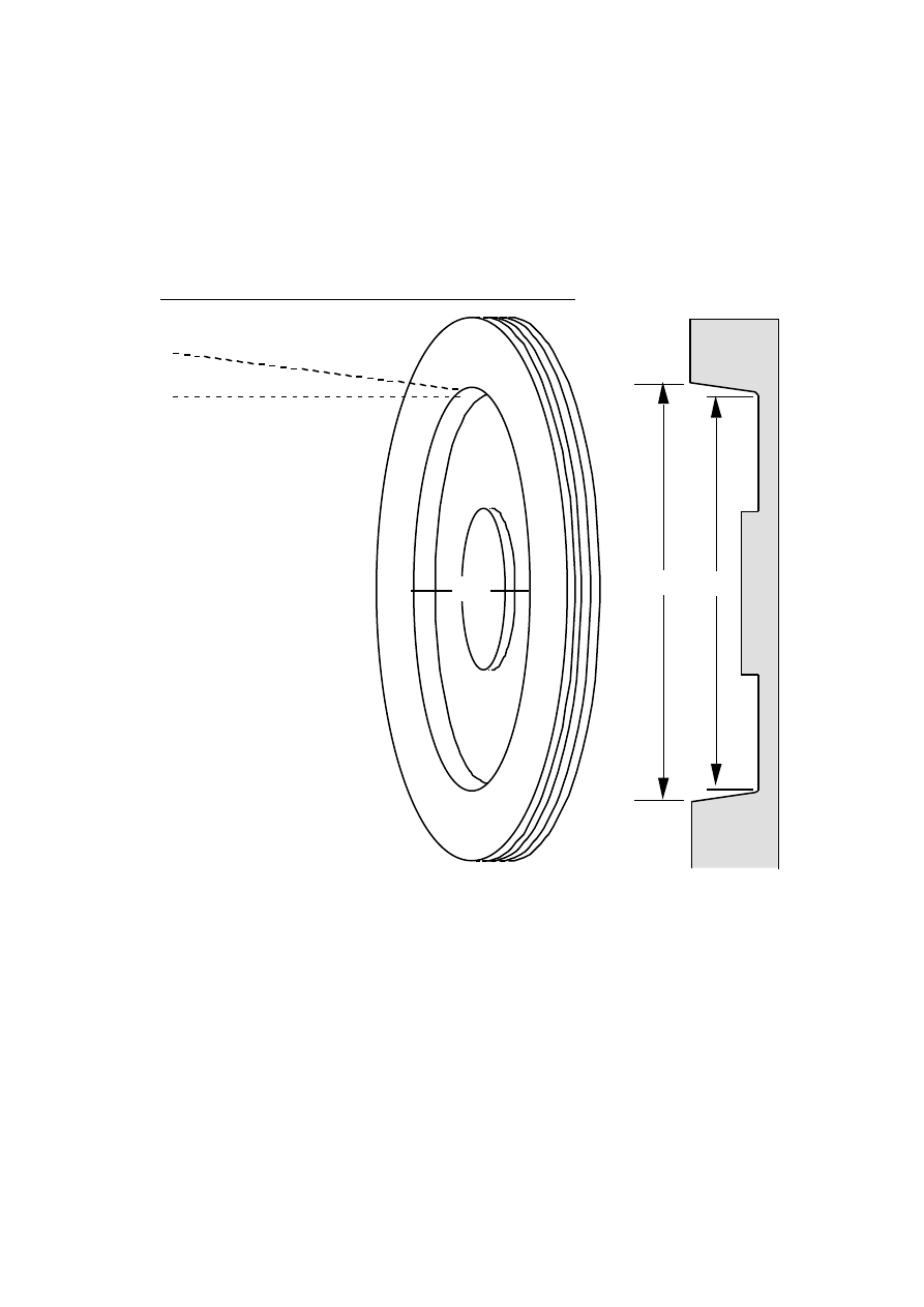
• Cut a smooth surface on the inner edges of the stack (diagram 17).
• The surface tapers at about seven degrees.
• The overall diameter at the outer edge is 380mm
• The diameter of the flat face is 360 mm.
• The corner inside is smooth (slight radius) not sharp.
17. THE SHAPE OF THE STATOR MOULD
7 degrees
380
SECTION
380 360
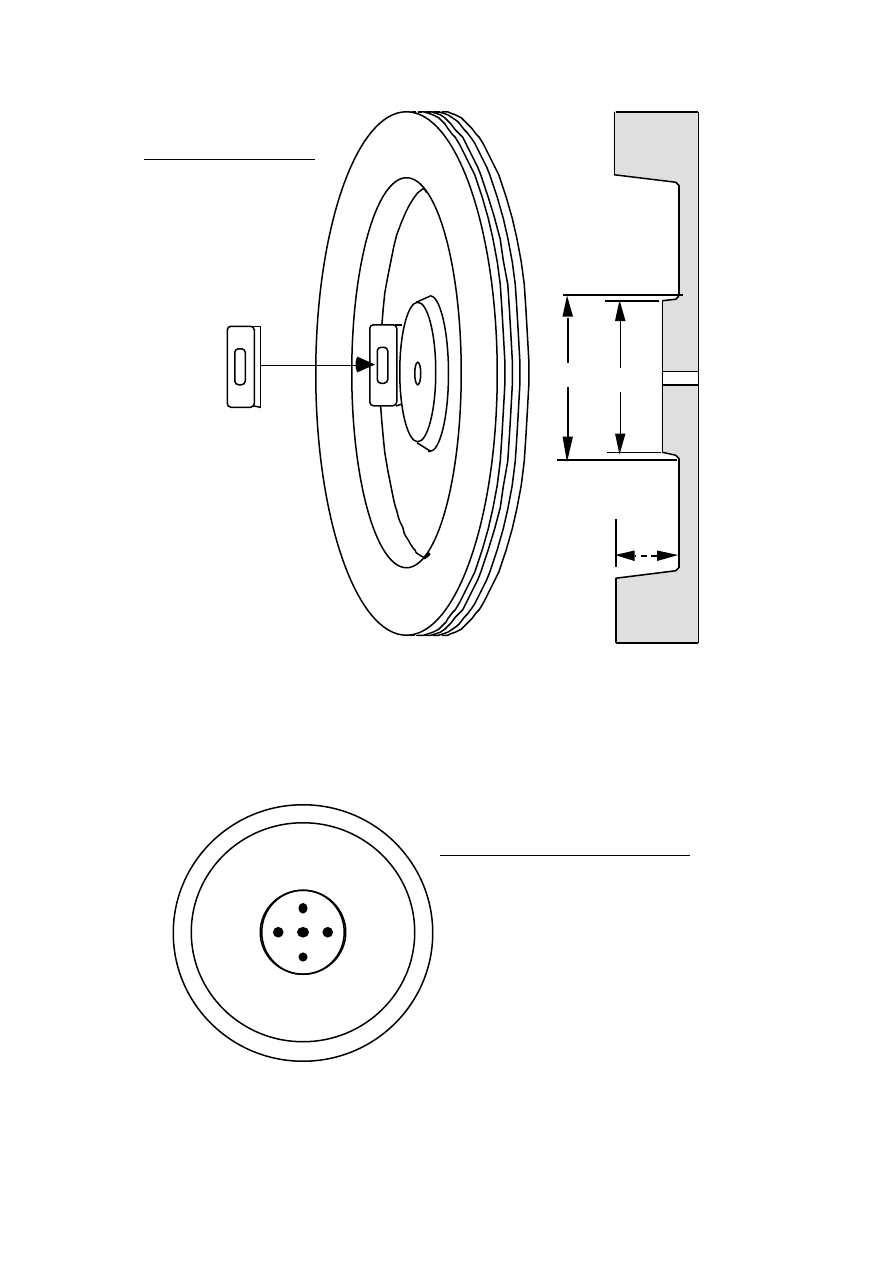
• Turn the inner disk down to 130 mm diameter on the face (see diagram 18), with a
taper. The corners are rounded as before.
PMG manual
page 19
June 2001
SECTION
HOLE
60
140 130
18. CENTRE DISK
CHECK THAT
THE COIL FITS
COMFORTABLY
• Place a coil against the face of the mould and check that it fits comfortably - if
not, then the hollow must be made a little larger, or the centre disk a little
smaller. In the end, the coil's centre must be at 250 mm from the mould centre.
• Remove the mould from the lathe or motor.
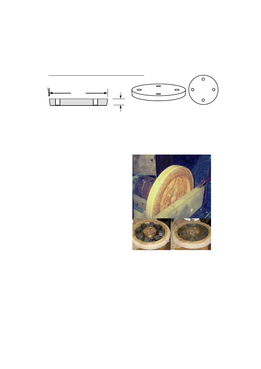
19.HOLES IN THE MOULD
Drill four holes in the central part which are used to separate the two moulds
(diagram 19). Screw some small pieces of plywood onto the underside of the mould
to make 'feet'.
PMG manual
page 20
June 2001
Stator Inner mould
• Drill a 12mm hole at the centre of each
• Glue them into a stack (diagram 20), using a 12mm bolt to
centre them.
• The stack is at least 45 mm thick, better 50 mm.
• Turn a 20 degree taper on the rim, and round off the corner,
so that the diameter reduces from 368mm to 325mm.
• Check that the outer mod fits over the inner mould, with a
6mm gap all around the edge. Then remove the inner mould
from the faceplate.
• Draw 2 lines on the larger face of the mould, 340mm apart
(diagram 21)
• Cut two flat faces, as shown in diagram 21
• Cut disks with diameter 370mm
SECTION
20 degrees
HOLE
368
325
45
20deg
20. INNER MOULD
Sawing flat faces
on the inner mould

PMG manual
page 21
June 2001
340
21. CUTTING FACES ON THE INNER
MOULD
FLAT
FACE
These two faces will create a thicker casting around the mounting studs.
Magnet rotor moulds
The PMG needs two magnet rotors. Only one mould is needed, but production is easier
if there are two moulds, so that two rotors can be produced at one time.
The outer mould (diagram 22) is similar to the stator outer mould, but simpler
22. ROTOR MOULD
315
20
7 deg
102mm
PMG manual
page 22
June 2001
Use the PCD jig to drill four holes to match the holes in the magnet disks.
Each magnet rotor also needs an inner disk mould (diagram 23), with the same
pattern of four holes.
23 MAGNET ROTOR INNER DISK
140
15
7 deg
All moulds are sanded down to a very smooth surface, and finished with polyurethane
varnish and wax polish. Do not use ordinary paint on the moulds. The heat of the
resin process will cause the paint to wrinkle and spoil the appearance of the casting.
Rotor mould being made and used
PMG manual
page 23
June 2001
Jigs for the stator
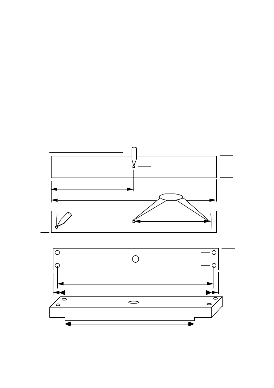
Stator studs jig (see diagram 24)
The stator needs four 8 mm supporting studs cast into it. These studs need a jig to
hold them in place, until the resin is set. This jig is made from wood 380 x 50 x
25mm. It must be made precisely, or the studs will not fit the spine later.
• Make a punch mark at the exact centre of the largest face (see diagram 24).
• Use dividers or compasses to mark arcs at a radius of 178 mm from this mark.
• Punch four marks on these arcs, 30 mm apart and 10mm from the edge.
• Drill through with an 8mm drill (using a smaller size first to be accurate). Use a
drill press, to drill the holes truly square.
• Remove some of the underside of the ends of the piece of wood, so as to prevent
contact with the fibreglass resin.
380
24. STATOR STUDS JIG
190
50
25
178
10
355
380
Ø12
Ø8
30
50
DRILL HOLES WITH A PILLAR DRILL FOR ACCURATE ALIGNMENT
320
30
30
PMG manual
page 24
June 2001
Paper templates (see diagram 25)
Fibreglass 'chopped strand mat' (CSM) is to be used in the stator. Make some paper
templates for cutting out the pieces of CSM. Later you can lay the templates on the
sheet of CSM, draw around them with a felt pen and then cut the pieces out.
380mm
140mm
75mm
MAKE THIS TEMPLATE BY LAYING
PAPER AROUND THE WALL OF THE
MOULD AND MARKING THE EDGES.
25. PAPER TEMPLATES FOR GLASSFIBRE CSM
PMG manual
page 25
June 2001
4. Stator construction
This section tells how to make a stator, using the jigs and moulds from section 3. It
is a good idea to wind a coil before making the stator moulds, so that the mould can
be checked for correct fit.
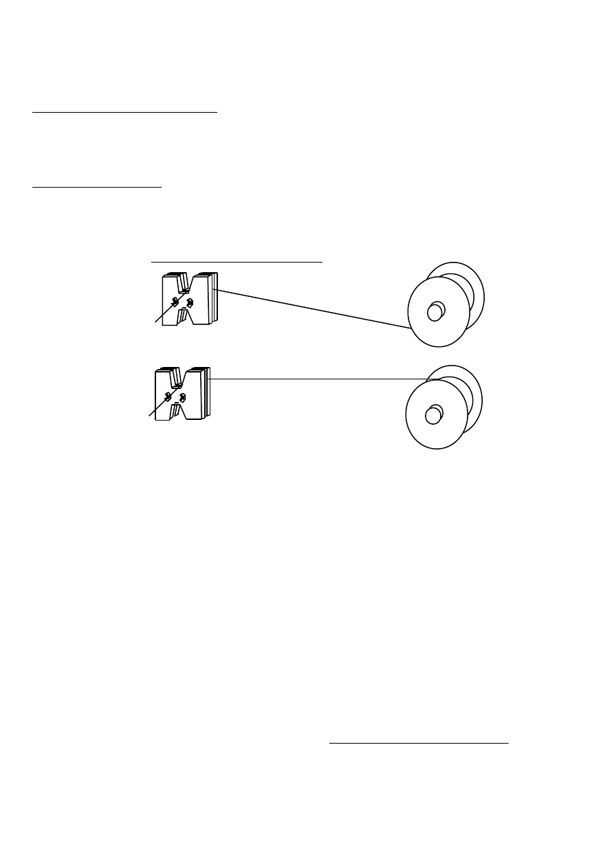
Winding the coils
• Mount the reel of winding wire on an axle behind you, in line with the coil former.
The wire should form an 'S' bend as it winds onto the coil (diagram 26).
REEL
(CORRECT)
REEL
(INCORRECT)
COIL FORMER
26. CORRECT WIRE FEED
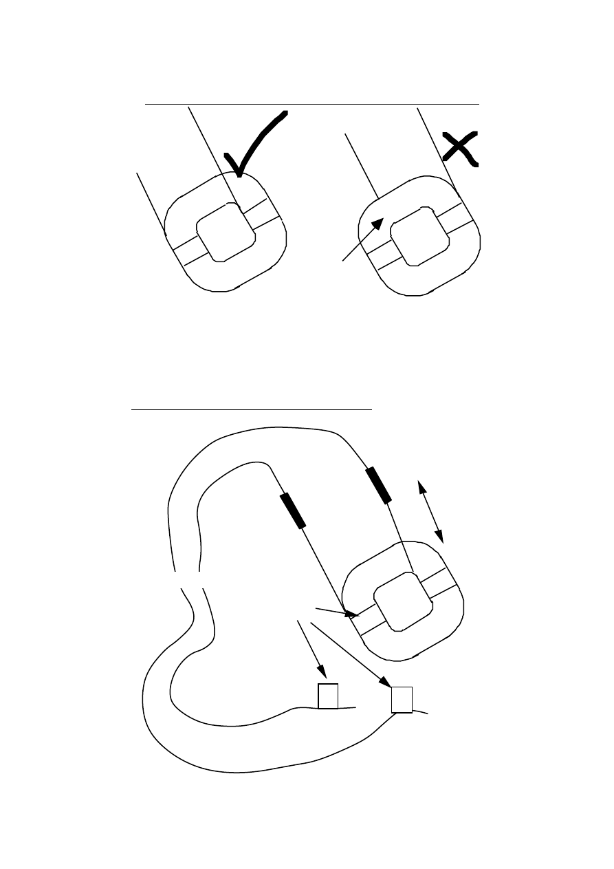
• Bend the tail of the wire 90 degrees, at a point 100mm from the end. Do not
handle the bend any other part of the wire; leave it straight. Bent wire does not
make a compact coil.
• Place this bend in the notch, so that the tail hangs out.
• Twist the tail loosely around one of the butterfly bolts.
• Grip the wire between the reel and the winder in a piece of rag to keep it tight.
• Wind the handle of the crankshaft.
The first turn lies against the cheek piece on the side where the tail comes out. The
other turns lie against each other neatly, without crossing over. Build the coil up in
even layers. Count the number of turns carefully. Normally there will be 100 turns.
• When the coil is complete, pass a piece of sticky tape under the coil on both sides
and bind it tightly. Do not cut off the winding wire until this is done, or the coil
will spring out, and loosen. Cut the tail of wire 100mm away from the coil.
• Remove the coil from the former, and wind five more coils in exactly the same
way.
• Place the coils on a table (so that they are all exactly the same way up (diagram
27) Check that the starting tail is on the upper surface, and not hidden under the
coil.
• Number the coils 1-6, writing on the masking tape.
PMG manual
page 26
June 2001
RIGHT
WAY UP
WRONG
WAY UP
27. THE COILS MUST ALL BE THE SAME WAY UP
STARTING TAIL
HIDDEN UNDER
• Scrape the enamel off the last 20mm of each tail of enamelled wire, until it is all
bright copper. (A hacksaw blade makes a very good scraper, when the edge has
been sharpened with a grinder.)
• Solder on tails of flexible wire (diagram 28).
1
MASKING
TAPE
1B
1A
100mm
FLEXIBLE WIRE
SOLDER
JOINTS
28. SOLDERING ON TAILS OF FLEX

PMG manual
page 27
June 2001
Suggested lengths of flexible tails:
coils 1 and 6 - 800 mm flex
coils 2 and 5 - 600 mm flex
coils 3 and 4 - 400 mm flex
• Cover the soldered joints with sleeving. Leave no bare copper showing.
• Label the tails with the coil number and the letter A or B.
A is for the start of the coil, B is for the finish. Do not mix them up.
Or use two colours: black flex for the starts and white for the finishes.
• Lay the coils out in the outer mould.
• Check that they will fit comfortably, and that the tails are long enough to remain
within the mould until the exit point between coils 3 and 4.
It is important to lay all the coils the same way up.
29. THE COILS IN THE MOULD
1
2
3
4
5
6
Holes shown black
Preparations for stator casting
The stator casting will contain:-
•
six coils
•
polyester resin and talcum powder (and perhaps pigment)
•
fibreglass mat (CSM)
•
four studs of 8mm x 100mm threaded rod
Also, be sure to have the moulds prepared properly. Sand them, seal them, polish
them. If PVA release agent can be got, then use it.
PMG manual
page 28
June 2001
Cut out pieces of fibreglass CSM, using the templates. There will be 2 circular disks
for laying flat in the outer mould. You also need enough curved strip pieces to cover
the inside wall of the outer mould in a double thickness of CSM. Overlap 25mm
between pieces.
When you are sure that you have everything to hand, start the resin casting process.
It is a good idea to read through the procedure first, and check that you understand it
all before you start. There are notes on polyester resins in section 8.
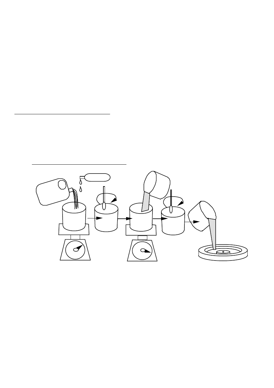
The stator casting procedure
Diagram 30 shows the procedure for weighing out the resin and the talcum powder.
The talcum powder is only used for bulk mixes (not thin layers with CSM), to
prevent overheating, and to thicken the mix. Different mixes use different weights -
follow the step by step instructions below. Diagram 31 shows all the parts coming
together.
200g
RESIN
CATALYST
3CC
400g
TALCUM
POWDER
200g
30. MIXING POLYESTER RESIN
Mix resin with catalyst thoroughly but slowly to avoid churning in air bubbles. Add
any talcum powder only after the catalyst is mixed. When the resin is mixed, use it
at once. After a few minutes in the mixing bucket, it will heat up, and begin to set.
Use exactly the right amount of catalyst. Resin casting needs less catalyst than
normal fibreglass work (about half the time). When the workshop is hot, put in less
catalyst. Casting thick layers of resin, put in less catalyst. If in doubt, make some
trial mixes of resin, to find out the correct amount of catalyst.
If there is no PVA 'release agent', then take care not to wipe the polish off the mould
with brush strokes. Apply the resin with a 'prodding' action.
PMG manual
page 29
June 2001
• Place the outer mould on some newspaper on a workbench.
• Mix 200g of resin, with 3cc of catalyst (and 15-30cc of pigment for colour, if
required). Use no talcum powder in the first two mixes.
• Paint this resin all over the inside of the outer mould. Do not paint it on top of
the island in the centre.
• Apply one layer of fibreglass mat (CSM), and paint more resin over it again, with a
poking motion to remove bubbles. Work the resin into the CSM.
• Apply a second layer of CSM to the wall, but keep one disk for later.
• Put the coils into the mould. The wire tails all come out in one place, between
coils 3 and 4.
• Mix another 100 g of resin with 2cc catalyst. Pour this over the wires of the
coils so that it soaks in. Avoid making 'pools' of resin.
• Mix another 600g of resin with 9cc catalyst and 600g of talcum powder. Pour
this mix into the spaces between the coils. The resin should fill the outer mould
until it is level with the island at the centre.
• Shake the mould vigorously, to remove air bubbles. Rotary motion and vibration
will help the resin to settle, and help any air bubbles to rise .
• Mix another 200g resin with 3cc catalyst and only 100g of talc. Put the second
CSM disk over the coils and paint it with this mix. Thoroughly wash out the paint
brush with thinners.
• Put the inner mould down inside the outer mould, and fit the 12 mm bolt though
the centre of both. Tuck the wiring neatly into the space between the moulds.
One flat spot on the inner mould sits over the part where the wires come out of
the stator. The resin will rise up the sides. Some resin may spill out.
• If necessary, pour resin gently into the gap between the moulds until it rises to
near the top of the female mould. You may need to mix another 100g of resin with
1.5cc of catalyst to do this. Keep notes of the amounts of resin used, for next
time.
• Place the jig (for the studs - diagram 24) over the inner mould, with one end over
the wire tails. Tighten the 12mm bolt with a nut. Insert the four 8mm studs into
the holes, with nuts on top. The studs should be immersed in resin for about half
of their length.
Six stages of the rotor casting procedure
PMG manual
page 30
June 2001
studs
j i g
inner
mould
CSM disk
coils
CSM strips
CSM disk
outer
mould
M12
bolt
31. STATOR CASTING
ELEMENTS
The casting is now complete. It should become slightly warm, and harden within
hours. If it does not begin to set within a few hours, then put it in a warm place to
speed up the process.
When the resin is fully hard, remove the casting from the mould. Be patient and
gentle if possible. Remove the jig from the studs. Tap the two moulds apart, using a
bolt in each of the holes around the central hole. Knock the casting out of the outer
mould by turning it over and knocking the edge of the mould gently against the floor.
PMG manual
page 31
June 2001
5. Rotor construction
The magnet rotor is also a casting. There is also a procedure later for assembling
the parts. First collect together the magnet plates, magnet blocks, stainless wire
rope, etc. as described next.
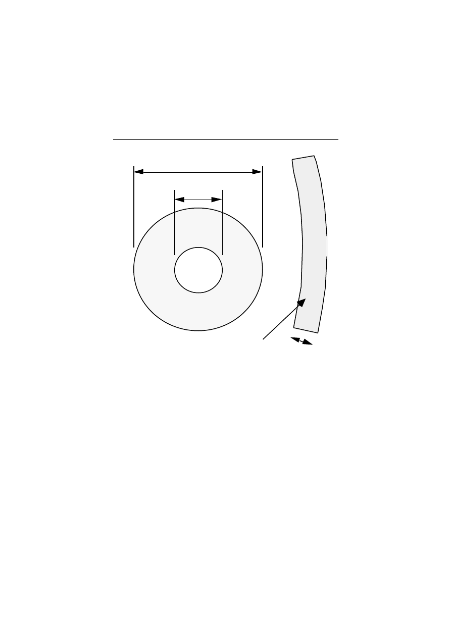
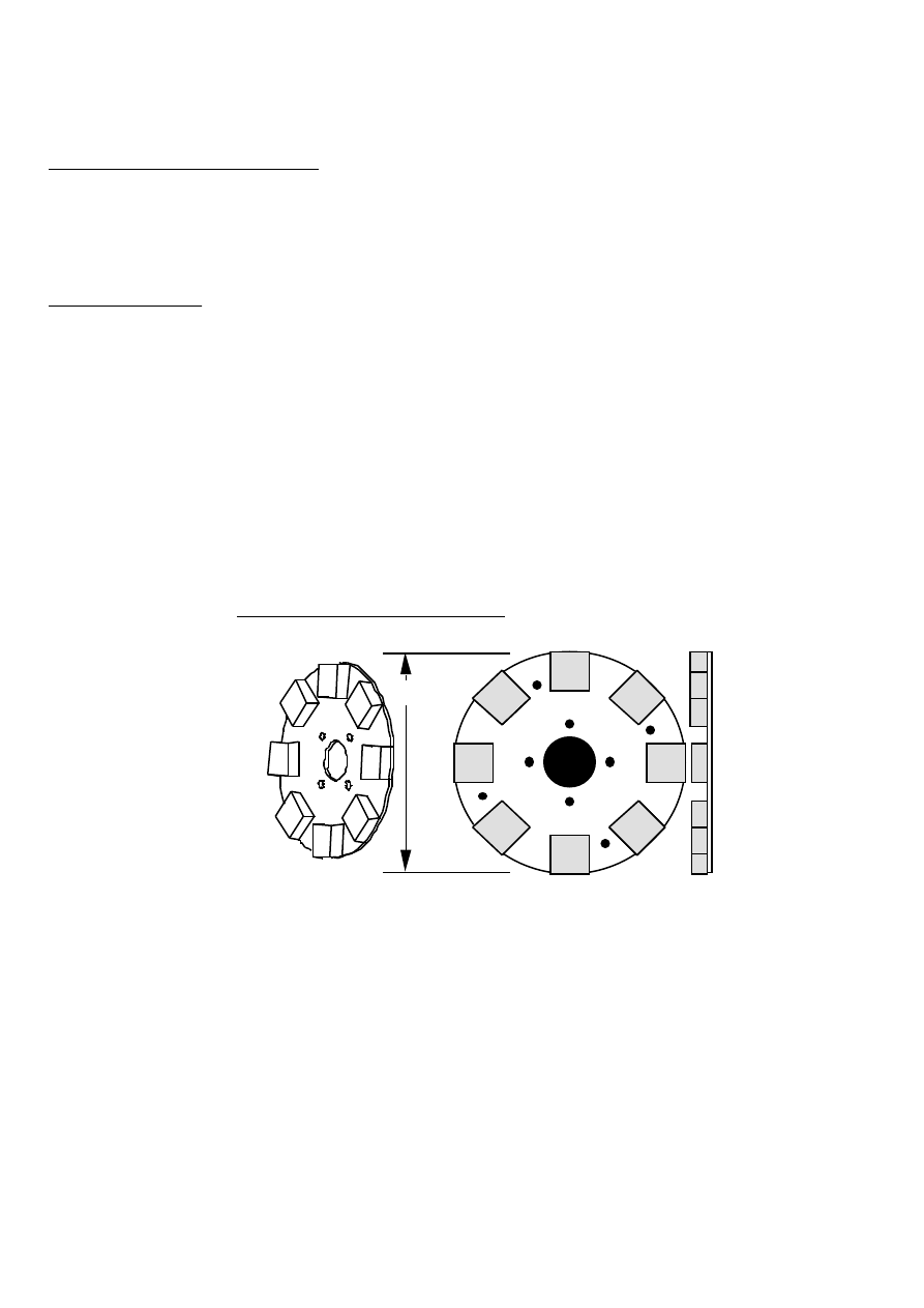
Magnet plates
Each magnet rotor is built on a steel disk, 6mm thick. See diagram 32. Do not use
aluminium or stainless steel for this disk! The disks have to be made of magnetic
material. The disk has holes to mount it to the hub - in this manual the hub has four
holes, each 10mm diameter, on a circle at 4 inches (102mm) PCD. If a different hub
is chosen, then all the jigs and moulds must match this hub.
At the centre of the disk is a 65mm diameter hole. There should also be four holes
drilled and tapped (threaded) for M10 rod between the magnet positions, at 220mm
PCD. Screw four pieces of M10 rod, 20mm long, into these holes. These will bond to
the resin and help to secure the casting onto the disk.
305mm
32. MAGNET ROTOR DISK
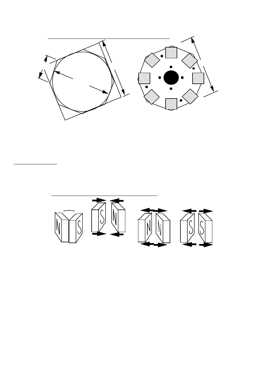
The magnet plates must be flat, not warped. It is not easy to cut the outer circle
without warping the plate. A guillotine can cut steel plate into an octagon (see
diagram 33), without warping the plate. This is an alternative way to make the
rotor disk. First cut a square, draw a circle on it, and then cut off the corners at 45
degrees. The length of each edge is 116 mm.
The magnets will be placed on the corners of the octagon.
PMG manual
page 32
June 2001
280mm
33. ALTERNATIVE SHAPE : AN OCTAGON
280mm
280mm
116
The central hole is made with a hole-saw or it can be cut out on a lathe.
Grind the steel disks until they are bright and clean, just before putting them in the
mould for resin casting. Remove any grease with spirits.
Magnet blocks
There are 8 magnet blocks on each rotor. Each block has a north pole and a south pole
(see diagram 34).
EACH BLOCK HAS
A 'N' AND A 'S' POLE
N AND S POLES ATTRACT
EACH OTHER
POLES WHICH ARE THE SAME
REPEL EACH OTHER
34. POLES ON THE MAGNET BLOCKS
Take care when handling the magnets. Magnets can damage floppy discs, music
tapes, credit cards and other magnetic media. Separate them from each other by
sliding them sideways. They attract each other with strong forces. Take care not to
let them fly together - they may break. Never use a hammer to assemble the PMG.
You may break a magnet or break the resin holding it.
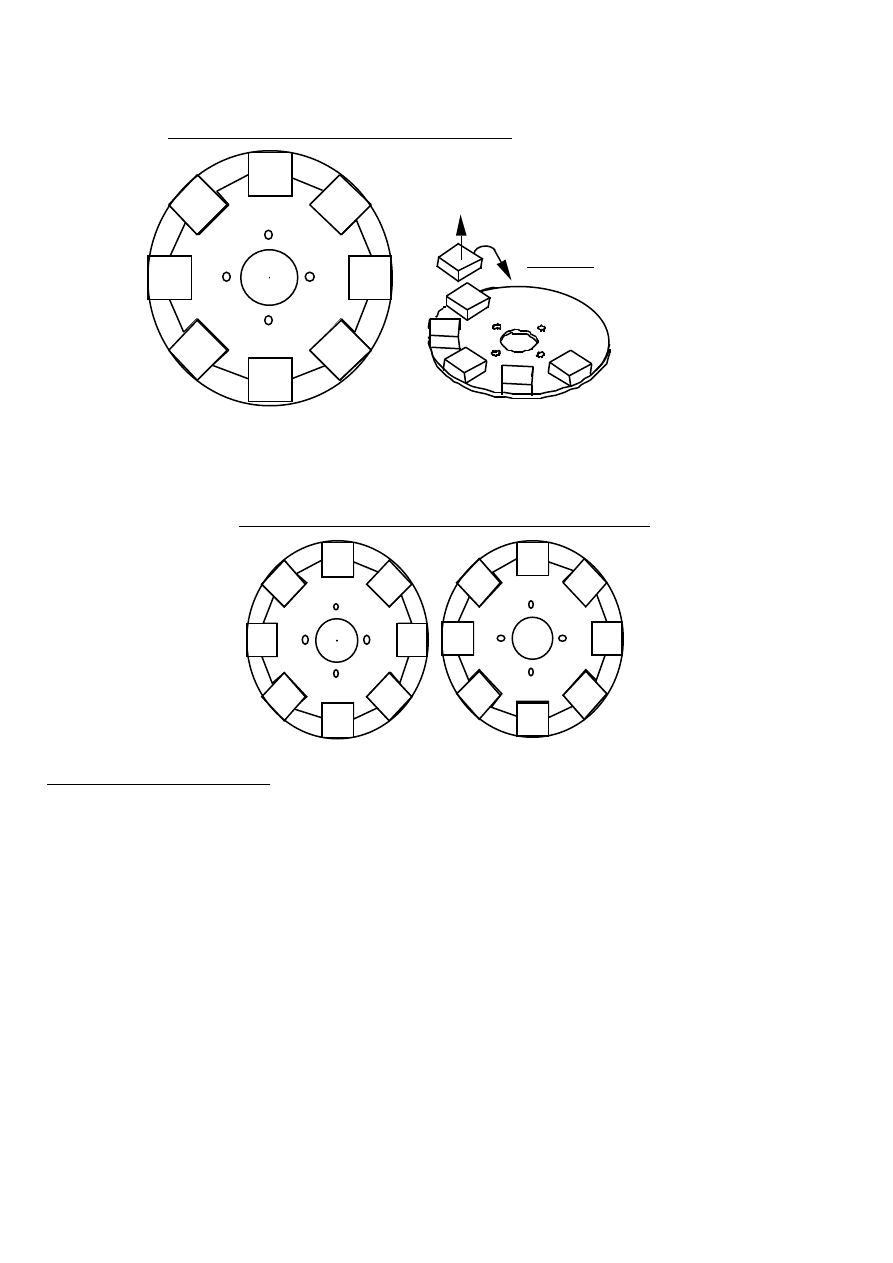
The top faces of the magnet blocks on the disk must alternate N-S-N-S-... There is a
method to check that you are doing this correctly, as follows. Each time a magnet
block is placed, hold it so that it repels the one before (see diagram 35). Then place
it without turning it over. When they are all in, check with another magnet: it will
be attracted, repelled, attracted, repelled, by each magnet in the circle.
PMG manual
page 33
June 2001
S
N
S
N
S
N
N
S
1. CHECK THAT THE BLOCK IS REPELLED
2. DROP IT INTO PLACE
WITHOUT TURNING IT OVER.
35. PLACING THE MAGNET BLOCKS
The two magnet rotors must attract each other when the mounting holes are aligned.
Check that the magnets next to the holes on one rotor are different from the ones
next to the holes on the other rotor (see diagram 36).
S
N
S
N
S
N
N
S
S
N
N
N
N
S
S
S
36. THE TWO ROTORS ARE NOT THE SAME
Stainless Steel wire
When the PMG is turning, the magnets will try to fly off the rotors. There is a large
centrifugal force pulling the magnet blocks to fly away. When we started building
these PMGs, the magnet blocks were simply glued to the steel disks. When the PMGs
turned fast, the magnets flew off, and the wind generators were destroyed.
Now we embed the magnets in a resin casting. Resin alone is not strong enough to
hold the magnets. It should be reinforced. Wrap wire around the outside of the
magnet rotors to hold the magnets in. Steel wire is strong enough, but steel would
take the magnetism from the magnet blocks. We use stainless steel because it is
not magnetic and it does not spoil the effect of the magnets. Stainless steel wire
cable is used on fishing boats.
Before using any resin assemble the parts dry. Put the stainless steel rope around
outside the magnets five times, and cut it off with a grinder or chisel. Tape it in
several places so that it is in a coil, ready to drop into place later.
PMG manual
page 34
June 2001
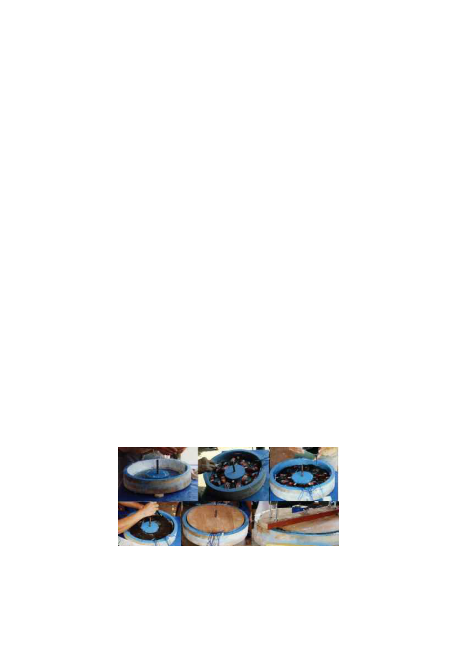
Rotor casting procedure
Before starting, check that everything is ready:
• the moulds are prepared with polish or release agent,
• the magnets and the magnet disks are clean and bright (no grease),
• 16 strips of CSM are ready to fit between the magnets
• the stainless steel wire is cut to length and taped
• the magnet positioning jig is ready
The amounts of resin mentioned in this procedure are enough for two magnet rotors.
37. MAGNET ROTOR MOULD ASSEMBLY
MOULD
STEEL DISK
MOULD
JIG
MAGNETS
STAINLESS
STEEL WIRE
FOUR BOLTS
• Place four bolts through the holes in the outer mould, from below (see diagram
37). Lay a steel disk in the outer mould. Place the inner mould on top. Check the
taper, and place the smaller face down, so that it can be easily removed after
casting.
• Mix 200g of resin with 3cc catalyst. Paint it all over the steel disk. Add 20g of
pigment for colour if required. Mix 100g talcum powder with the remains of the

PMG manual
page 35
June 2001
resin. Pour this mix around the edge of the disk until it fills the gap, level with
the top of the steel disk.
• Place the magnet positioning jig onto the bolts. Place the magnet blocks on the
steel disk, within the positioning jig. Take care that the poles of the magnets
alternate - north, south, north, south.. Before you place a magnet on the disk,
check that the underside of the magnet is repelled by the one next to it (diagram
35). When all the magnets are in, remove the positioning jig, and use it for the
next magnet rotor. Remember : position the magnet blocks differently, so that the
two rotors attract each other.
Take care not to knock the magnets out of place, or they will slide together under
the magnetic attraction.
• Fit nuts to the four bolts and tighten the central disk down onto the steel disk.
• Mix 500g of resin with 7cc of catalyst. Add 300g talcum powder. Lay small
strips of CSM between the magnets and into the gap at the edge. Add resin until
the CSM is soaked. Poke it, or vibrate it, to remove bubbles.
• Lay the coil of stainless steel wire loosely around the outside of the magnets,
below the top of the mould. Do not let the wire fall below the magnets. Let it sit
on the CSM. Take care not to move the magnets around.
• Mix 500g of resin with 7cc of catalyst. Add 300g talcum powder. Fill the spaces
between the magnets until the resin mix reaches the top of the mould.
Leave the rotor castings to set hard (several hours) before you remove them from the
moulds. Be patient when removing the rotors from the moulds. Do not use violent
hammer blows which may damage them. Hit the mould, and not the rotor.
Four stages of the rotor casting procedure
PMG manual
page 36
June 2001
6. Assembly
Rotor balancing
Each rotor should be balanced, or the PMG will shake when it is turning. The whole
PMG needs to be balanced again at the end, because the rotors may not be mounted
exactly centrally. A different procedure is used for the final balancing in Section 6.
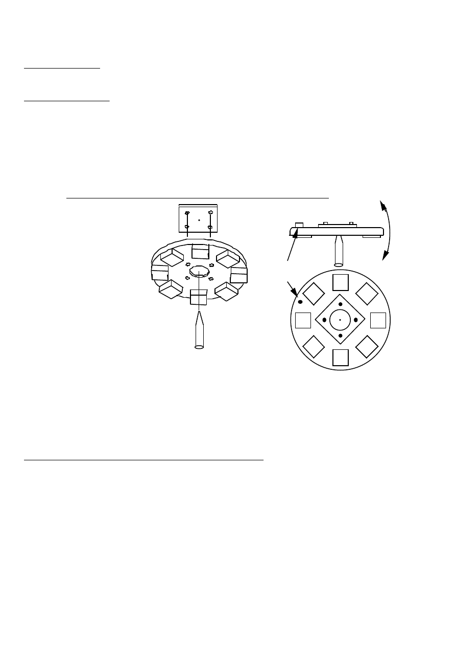
To balance a magnet rotor (see diagram 38), first attach the PCD jig (from diagram
11), using four bolts. Then balance the rotor on a spike as shown:
PCD JIG
MAGNET ROTOR
SPIKE
38. ASSEMBLY OF THE BALANCING JIG AND SPIKE
SMALL
WEIGHT
If the rotor will sit level, then it is balanced. If it will not sit level, then add small
weights to it, or drill out some of the resin between magnets, until it will sit level.
Turn the PCD jig around on the rotor, and check it again. Replace any weights with
pieces of M10 threaded rod, screwed into holes in the resin between the magnets.
PMG spine and bearing hub (see diagram 39)
Make the spine of the PMG from a 380mm length of 'box section' steel tube
50x25x4mm (sometimes called RHS). Mark the exact centre of one large face, and
then mark four 8mm holes, in the same way as for the 'stator studs jig'. It could
also be possible to use the stator studs jig to help drill the holes.
The hole at the centre is 25mm (or to suit the shaft used). Drill this with a hole-
saw, or bore it on a lathe.

PMG manual
page 37
June 2001
355
380
Ø25
Ø8
30
50
DRILL HOLES WITH A PILLAR DRILL FOR ACCURATE ALIGNMENT
39. THE BOX SECTION SPINE
Weld the shaft in the 25mm hole. Take care to hold the shaft as square as possible
(90 degrees) to the spine, when welding it.
The bearing hub (diagram 40) fits on the shaft. It has two 50x25 mm deep-groove
ballraces in it, with a spacer between them. It needs a plastic cap over the end to
keep dirt out of the bearings.
Do not forget to grease the bearings. Pack them with grease around half of their
circumference only. Do not fill them entirely or they will become stiff to turn.
Ø10
Ø120
PCD102
Ø65
8
63
20
35
Ø32
25
25
Ø25
40. THE BEARING HUB
PMG manual
page 38
June 2001
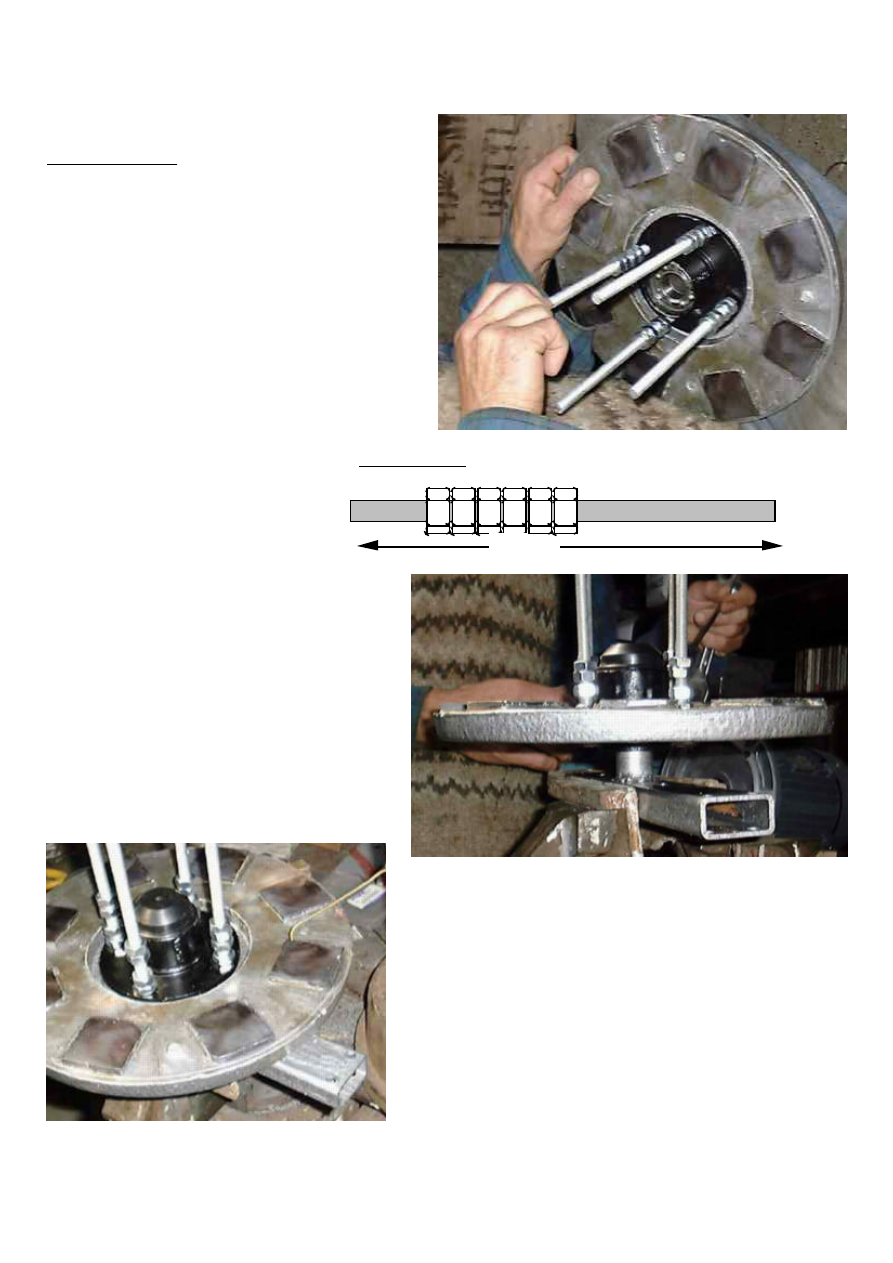
Photos show the rear magnet rotor being fitted
PMG assembly
• Cut 4 pieces of M10 threaded rod,
each 200 long. They are used as
studs to hold the magnet rotors to
the hub. The wind turbine blades
will also mount onto these studs.
• Put 6 nuts onto each stud) see
diagram 41).
• Fit the studs through the holes in the
bearing hub, from the front
• Put the rear magnet rotor onto the
ends of the studs.
• Put a nut on the end of
each stud, and tighten the
other nuts down, so that
the rear magnet rotor is
attached to the back of
the hub flange. The outer
end nut should be sealed
with paint or thread-
sealant.
• Place the spine in a vice with the
shaft upward. Place the hub onto
the shaft. Do not hammer the
magnet rotor while fitting.
Fasten the hub to the shaft with a
nut and split pin. Do not over
tighten the nut. Fit a dust cover
over the end of the bearing hub.
• Rotate the magnet rotor past a piece of
brass wire. Do not use steel wire, because
it is attracted to the magnets. The magnet
faces should all be at the same height +/-
0.5mm. If not, use very thin shims between
hub-flange and rotor-disk, to adjust the
rotor.
• Using a spirit level, adjust the spine in the
vice until the magnet rotor is level. Check
both ways: north-south and east-west.
• Take the stator. Fit one 8 mm nut onto each
support stud. Screw them right down.
10mm
THREADED ROD
200mm
41. STUDS

PMG manual
page 39
June 2001
• Place the stator over the rear
magnet rotor and fit its support
studs into the holes in the spine.
Fit more 8 mm nuts to the ends of
the studs.
• Slowly lower the stator, and
rotate the rear magnet rotor. Keep
the stator level in both directions.
You will hear a sound when the
highest magnet touches the stator.
• Use the nuts to raise the stator
equally 1mm on all four studs.
• Fit some washers to the 10 mm
studs which hold the rotors.
Always the same number of nuts
and washers on each stud. A total
of six nuts and two washers may be enough. Then fit the front magnet rotor.
• If the front magnet rotor is less
than 1mm from the stator at any
point, then add more washers
under it. If it is much more than
1mm from the stator then remove
washers. To find the correct
number it is necessary to remove
washers until it begins to rub the
stator. Then add 1mm.
• When the front rotor is 1mm from
the stator, then fit more nuts on
top, and tighten them securely.
Electrical Parts
The next section (Section 7) will describe how to connect the rectifier to the stator.
I recommend using two 'single phase bridge rectifiers' (see diagram 42). They come
in blocks 30 x 30 mm. The positive terminals are both connected to the battery
positive terminal. (They are often at right angles to the other three. ) Both negative
terminals are connect to the battery negative. The remaining four terminals are for
AC connection to the stator. You will probably only need to use three of these,
connected as desired to suit the speed (see Section 7).
Fitting the stator
Fitting the front magnet rotor

PMG manual
page 40
June 2001
42. RECTIFIERS ETC.
NEGATIVE TERMINALS
+
+
FIXING HOLES
HEATSINK
BLOCK
CONNECTOR
BRIDGE RECTIFIERS
RECEPTACLE
CONNECTOR
'Block connectors' are useful for connecting the wires from the stator. Alternatively
soldering or crimping would be fine.
Use solder, or crimped 'receptacle' connectors, to connect wires to the rectifiers.
Take care not to overheat the rectifiers while soldering. Bolt the rectifiers onto the
heatsink, which will probably look like the one in the diagram, but can be any piece
of aluminium approximately 250 grams or more in weight.
Keep all the connections under a weatherproof cover.
Two bridge rectifiers
PMG manual
page 41
June 2001
7. Testing and connecting
Check that the PMG has no faults before it is put into use. It will be much easier to
correct the faults now, than to return the unit to the workshop later.
Mechanical testing
Mount the spine vertically in a vice. The magnet rotors are free to move. The shaft
is horizontal, as it will be in a wind generator. Check that the wires are not
touching each other, creating a short circuit which makes the PMG harder to turn.
Check that the rotor will spin freely.
Spin the rotor and listen for sounds. There should not be any scuffing or brushing of
the rotor, as it turns. It should spin freely for several seconds and gradually come
to a halt. If it slows down rapidly then there may be an electrical fault, or the
bearings may be over-tightened.
Grasp the stator with both hands. Push one side backward while pulling the other
side forward, while the rotor is spinning. It must not touch the rotor. If there is a
rubbing sound, then it may be necessary to disassemble the PMG and assemble it
more carefully, with more space between the rotor and the stator. Or it may be
possible to correct the problem by making minor adjustments to the stator mounting
studs.
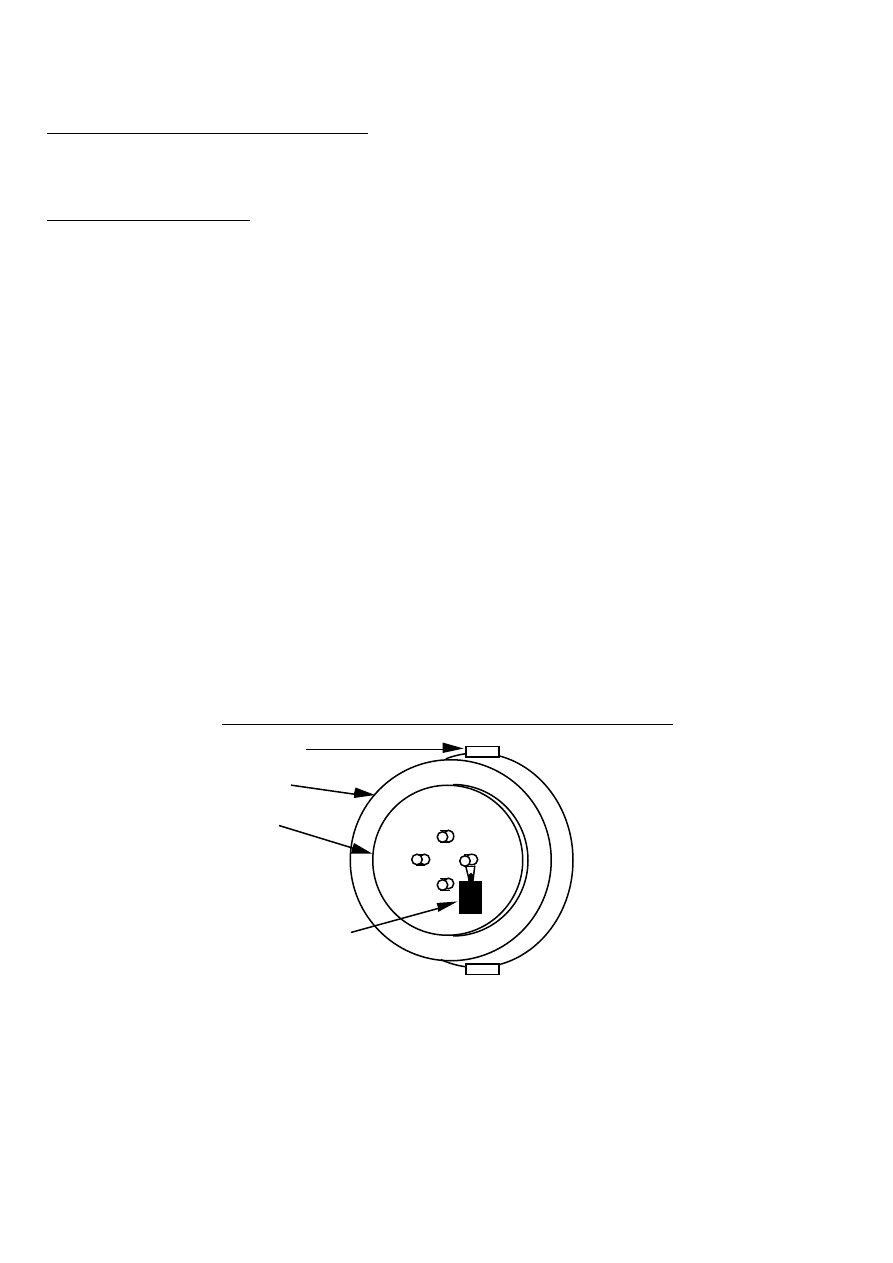
Stop the rotor with one of the studs in the 3 o'clock position (diagram 43). Hang an
object weighing 100 grams on this stud. The rotor should begin to turn clockwise.
If it will not turn, then the bearings may be over-greased or too tight.
SPINE
STATOR
ROTOR
43. HANG A WEIGHT ON ONE OF THE STUDS
100g WEIGHT
Checking the balance
The rotors have already been balanced in section 6. The wind turbine blades must
also be balanced in the same way. When the unit is assembled, you should check the
balance again using the new procedure below. This is necessary because the rotor
disk may not be perfectly central on the PMG shaft.

PMG manual
page 42
June 2001
Repeat the starting test (diagram 43) with each of the four rotor studs in the 3
o'clock position. Try different weights, and find the lightest weight which will
start the rotor turning. If one stud needs much more weight than another, then the
rotor is not balanced. Fix small weights to the rotor until the balance is correct.
Electrical testing
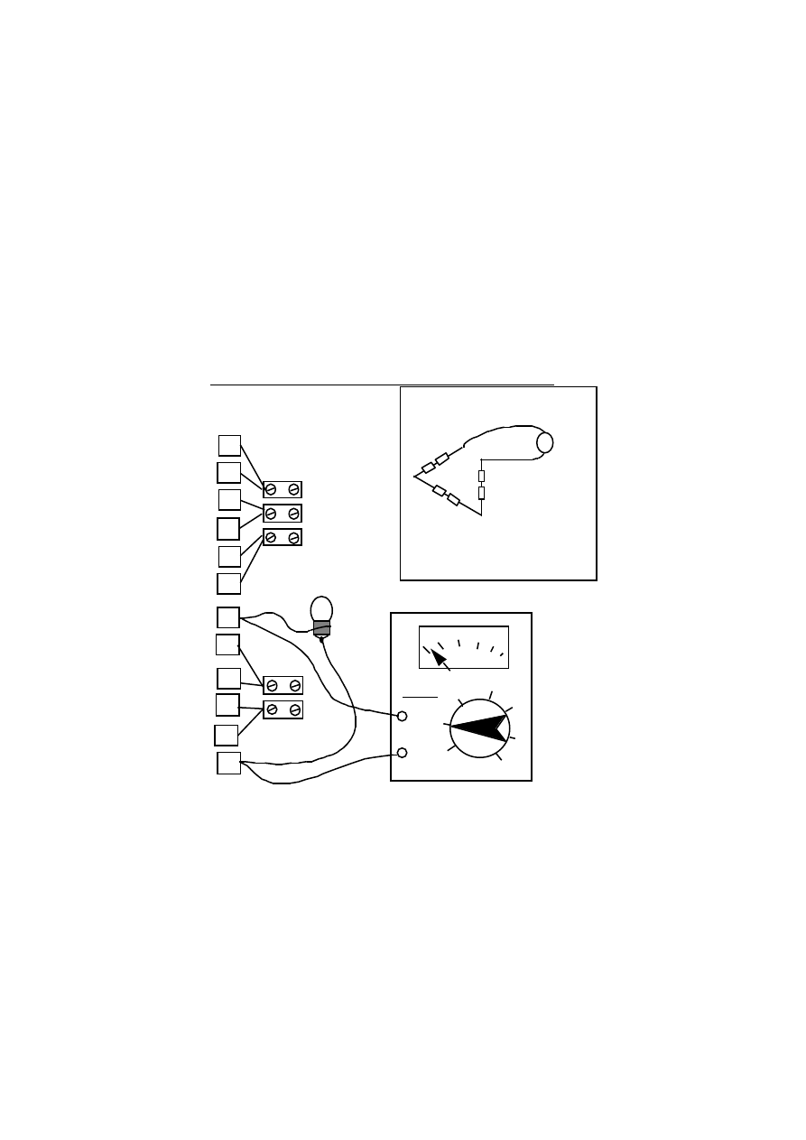
Coil connection test
It would be helpful to have a multimeter when testing the PMG, but it is possible to
do some basic tests with a 3 volt torch bulb. See diagram 44.
• Connect the wires 1B to 4A, 2B to 5A, and 3B to 6A. (Series connections of pairs
of coils which are in the same phase.)
• Set the multimeter to '10VAC' or similar (if you have one).
• Connect the meter, or a bulb, between the wires marked 1A and 4B.
1A
2A
3A
1B
4A
2B
5A
3B
6A
4B
5B
6B
CIRCUIT
SCHEMATIC
DIAGRAM
WIRING
DIAGRAM
BLOCK
CONNECTOR
ACV
100
10
1
BULB OR
METER
44. TESTING THE COILS
MULTIMETER
BULB
SERIES
CONNECTIONS
TEST THESE
NEXT
• Rotate the PMG slowly by hand, about one revolution per second.
• The meter should give a reading of about two volts, or the bulb should flicker.
• Repeat the test with two more pairs of wires: 2A and 5B, 3A and 6B.
In each case the result should be the same.
PMG manual
page 43
June 2001
If there is no reading, or a very low reading, then check that the series connections
(1B-4A, 2B-5A, 3B-6A) are correct. If all these connections are good, then it is
possible that one coil has been reversed (placed upside-down).
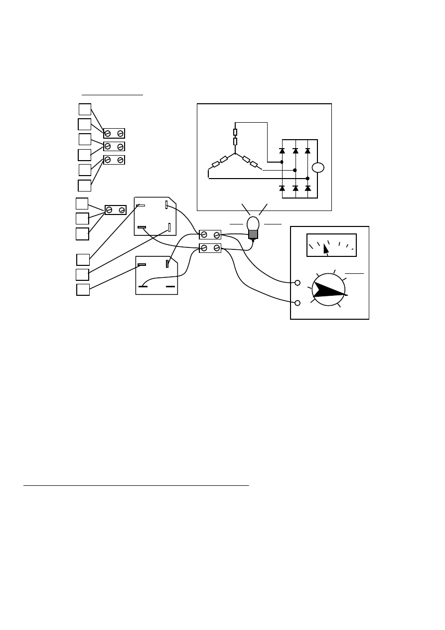
If any coils have been reversed, then it is necessary to do another test (see diagram
45), to find out which one is at fault. Connect 4B-2A and 5B-3A as shown in the
diagram. Now test between 1A and 6B. There should NOT be more than a very small
voltage. If there is a voltage, or the bulb lights up, then reverse the connections
(swap A for B) on the coils until the voltage drops to a very low level.
When the faulty coil has been found, label the tails again, with A and B at the correct
ends.
1A
2A
3A
1B
4A
2B
5A
3B
6A
4B
5B
6B
CIRCUIT
SCHEMATIC
DIAGRAM
WIRING
DIAGRAM
BLOCK
CONNECTOR
ACV
100
10
1
BULB OR
METER
45. CHECKING FOR A REVERSED COIL
MULTIMETER
BULB
SERIES
CONNECTIONS
There will always be a small voltage in this test, because the coils are not perfectly
positioned in the mould. If the test gives more than one volt, then it should be
possible in future to make a better stator by placing the coils at exactly equal
distances apart in the mould.
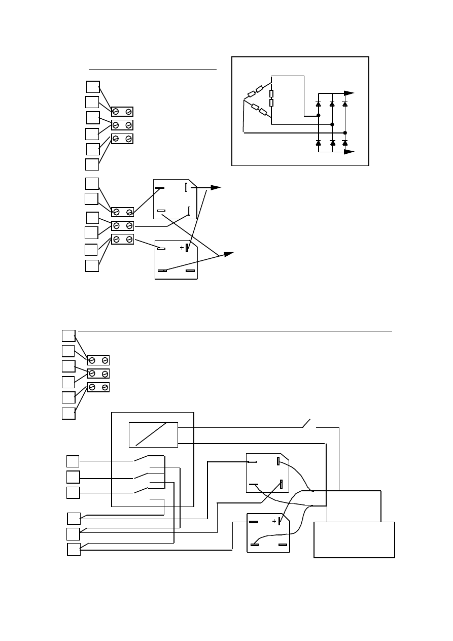
DC output test
When these tests have been completed and the results are correct, then connect the
rectifier, as shown in diagram 46. Connect the tails 1A, 2A and 3A together.
Connect each of 4B, 5B and 6B to any three of the rectifier AC terminals (marked
with 'S' symbol). This is the 'star' connection. Connect a bulb to the output. If
possible, also a multimeter on 10 VDC (or similar).
PMG manual
page 44
June 2001
1A
2A
3A
4B
5B
6B
+
+
CIRCUIT
SCHEMATIC
DIAGRAM
1B
4A
2B
5A
3B
6A
BLOCK
CONNECTOR
SERIES
CONNECTIONS
DCV
10
MULTIMETER
BULB
V
46. DC TEST
RECTIFIERS
COILS CONNECTED STAR
Rotate the rotor by hand as before, approximately one revolution per second (60
rpm).
The meter should show a steady reading around 4 volts DC (or 3 volts with the bulb
present). The bulb should glow with a steady light, not flickering as before.
If there is no reading, or the bulb flickers, then there is a faulty connection or a
faulty rectifier. Check the connections carefully. Try another rectifier.
You can also test the PMG without a bulb or a meter. Simply connect the positive and
negative wires from the rectifiers together (all four) in a 'short circuit'. Now try to
turn the PMG. It should be stiff but smooth to turn. If it trembles as you turn it then
there is a fault.
Connecting the PMG to the 12 volt battery
Star and Delta connections
For low windspeeds, connect the coils 'star' as above. For high winds, and higher
current output, connect the coils 'delta', as in diagram 47.
PMG manual
page 45
June 2001
1A
2A
3A
1B
4A
2B
5A
3B
6A
4B
5B
6B
+
TO
BATTERY +
TO BATTERY -
BATTERY +
BATTERY -
CIRCUIT
SCHEMATIC
DIAGRAM
47. DELTA CONNECTION
BLOCK
CONNECTOR
BLOCK
CONNECTOR
DELTA CONNECTION GIVES
MORE CURRENT WITH
BETTER EFFICIENCY AT
HIGHER SPEEDS.
It is also possible to wire a relay (see diagram 48) which will switch the
connections from star to delta and back as desired.
48. USING A RELAY TO CHANGE BETWEEN STAR AND DELTA
+
1B
4A
2B
5A
3B
6A
BLOCK
CONNECTOR
SERIES
CONNECTIONS
1A
2A
3A
4B
5B
6B
3 POLE C/O RELAY (3P2T)
12 VOLT BATTERY
+
SWITCH
-

PMG manual
page 46
June 2001
Yet another option for connecting the stator
At the time of writing this document, the above arrangement (using a relay to change
the connections) is still under development. Later, an electronic control circuit will
be available to automate the changeover. This is all very complex, and it so it can go
wrong.
If you do not wish to have to change the connections between low and high
windspeeds, then the PMG will still work. However, the efficiency will be slightly
less. Three are two options:-
• If you expect mainly low windspeeds, then you can simply use the star connection
shown in diagram 46.
• If you also need higher power in higher winds, you can use a 17AWG wire (1.2 mm
diameter) to wind coils with 200 turns each. Then you can connect one group in
delta and one group in star as shown in diagram 49. Note that you need six AC
terminals on the rectifiers so you will need three rectifier blocks.
1A
2A
3A
4A
5A
6A
4B
5B
6B
1B
2B
3B
+
+
49. STAR/DELTA CONNECTION
BLOCK
CONNECTOR
BLOCK
CONNECTOR
+
BATTERY
POSITIVE
BATTERY
NEGATIVE
USE 200 TURNS PER COIL
PMG-to-Battery Cable size
The cable from the PMG to the battery can be either three-phase-AC or DC. If the
rectifier is mounted at the wind generator, then it will be DC. This is only slightly
more efficient than three phase AC.
PMG manual
page 47
June 2001
At 12 volts, the size of the cable must be large. Even if the current is only 15 amps,
it is advisable to use a heavy cable. For a distance of 20 metres, the recommended
size is 6 mm2 (10AWG). The diameter (thickness) of each copper wire is about 3mm.
A 15 amps current flowing in this cable will lose 15% of the power from the wind
generator as heat in the cable. If the cable is longer, it should be heavier, in direct
proportion.
Electrical Safety
There is no danger of electric shock from a 12 volt battery. But if the wind
generator is disconnected from the battery, and running fast, then the voltage will
be higher than 12 volts, maybe as high as 50 volts. Do not run the PMG at high speed
without a battery connected.
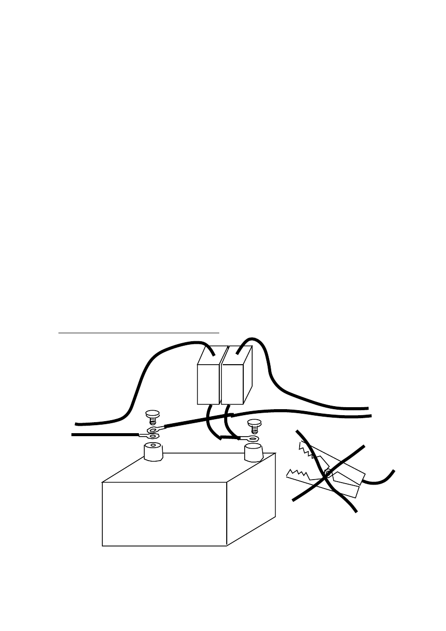
The battery contains stored electrical energy. When there is a short-circuit fault in
the wiring from the battery, for example the positive and negative wires touching
each other, this energy is released in a very high current. The cable will heat up and
burn. Therefore it is necessary to use a fuse or a circuit breaker on every wire
which attaches to the battery positive terminal. Use one fuse for the wind generator
and a separate one for the cable to the load (the lights, or whatever uses the power).
See diagram 50.
-
+
12 VOLT BATTERY
FUSES OR
CIRCUIT
BREAKERS
CABLE FROM
WIND
GENERATOR
CABLE TO
LOADS
DO NOT USE 'CROCODILE CLIPS'
FOR PERMANENT CONNECTIONS
50. CONNECTING THE BATTERY

PMG manual
page 48
June 2001
Battery acid is bad for the clothes and the skin. Do not splash it. Be especially
careful of the eyes. If there is an accident, the best cure is to flush with plenty of
water.
Batteries produce hydrogen gas, which is very explosive. Do not make sparks near a
battery or it may explode, and throw acid in the eyes!
Battery Charging
Lead acid batteries should be kept in a charged condition. In the case of a wind
powered system, you may have to wait for a wind to charge the battery. But be
careful not to discharge the battery too deeply, or to keep it too long in a discharged
state, or it will be damaged (sulphated) and become useless. Stop using a battery
before it is fully discharged. If there is a problem with the wind generator, then
charge the battery from another source within two weeks.
Charging the battery too hard will also damage it. At first, when the battery is
discharged, it is safe to use a high current, but later the current must be reduced or
the battery will overheat and the plates will be damaged. The best way to fully
charge a battery is to use a small current for a long time.
Watch the battery voltage. If the battery voltage is below 11.5 volts, then it is
being discharged too much. If the voltage is high (over 14 volts) then the battery
charging current is too high. Use less current or more current in the loads to correct
these problems. If there is no voltmeter available, then the user should watch the
brightness of the lights and follow these rules:-
• Dim lights, mean low battery. Use less electricity!
• Very bright lights mean too much windpower. Use more electricity!
A good way to use more electricity is too charge more batteries in windy weather,
perhaps charging batteries from neighbours' houses.
There are simple electronic circuits which can regulate the battery voltage
automatically. They are called 'low voltage disconnects' and 'shunt regulators'. If
the user is not willing to watch the battery voltage, then it is necessary to fit a
disconnect and a regulator.

PMG manual
page 49
June 2001
8. Additional information
Using polyester resin
Polyester is the plastic substance used in fibreglass work for building boats, car
body parts, etc. Various things are added to it to make it work better for various
jobs. Talk to your supplier and explain what the resin is to be used for. Your
supplier should be able to help you.
Hardeners
There are two systems used to harden polyester resin, and each system uses two
chemicals. For resin casting and most fibreglass work we use peroxide and cobalt.
('Body filler pastes' use the other system.)
Cobalt is a purple fluid. Ask the supplier to mix the right amount of cobalt into the
resin. After it is mixed, the resin must be stored in the dark, or it will harden.
Peroxide is a hazardous chemical. Avoid contact with skin. Store in a PVC
container, in the dark, below 25 degrees C. Never mix it with cobalt (except for the
cobalt already in the resin), or it will explode. Mix very small quantities (about 1-
2%) of peroxide with resin or it will overheat.
Wax-free 'Air inhibited' resin 'B'
This type of resin is used for 'gel-coats' on boat moulds, where the resin is going to
be built up in stages. We do not recommend using this resin for the PMG. Any
exposed surface will remain tacky indefinitely. Ask for resin 'A', or better still
'casting resin'.
Thixotropic additive
A special powder of very light silica is often added to resin to make it thicker, so
that it is easier to spread it with a paint brush. This powder is not needed for
casting resin . If it is already added, it does no harm.
Styrene monomer
Approximately 35% of the resin as supplied is styrene monomer. This is used for
thinning the resin. It causes the smell. It is possible to add a little more styrene
monomer (10%) to make it more liquid.
Pigment
Pigment is used to colour the casting, if a coloured finish is desired. Add pigment to
the first mix, which will be on the outside of the casting. Add no more than 10%
pigment to the mix. It is not necessary to add pigment to the resin. Without
pigment, the casting is transparent and the coils are visible.

PMG manual
page 50
June 2001
Fibreglass
The resin has almost no strength without fibreglass. It is available in sheets of
'chopped strand mat' (CSM). It is also possible to buy just chopped strands, and to
mix them with the resin. This is useful for the magnet rotor castings. Add a little
resin to the fibreglass, and press out all the air bubbles, before adding more resin.
Talcum powder
Talcum powder is a cheap filler which can be mixed with the resin after the peroxide
has been added. It makes the resin mixture much cheaper, and a little thicker. Resin
can be mixed with up to twice its own weight of talcum powder. The powder also
helps to reduce the heat build-up in large resin castings.
Mould preparation
Polyurethane varnish
Ordinary paint should not be used on moulds.
Better to use nothing. If possible, use
polyurethane varnish. This will prevent moisture
coming out of a mould made from wood, plaster
or clay. Smooth the varnish off with sandpaper
before polishing it.
Polish
Polish the mould several times before using it
first time. Rub all the polish off with a rag and
then leave it some hours and do it again.
Silicone polish is not compatible with PVA
release agent. Use wax polish.
PVA Release agent
Paint this over the mould and let it dry. It forms
a sheet of PVA, which greatly helps to separate
the casting from the mould.
Using painted moulds in Peru

PMG manual
page 51
June 2001
Using the PMG for hydro power
The PMG can also be used for charging batteries from small hydro turbines. It will
be ideal for low head, low power sites, because it is efficient even when producing
only a few watts. It can also be used for higher head higher power sites, because it
is capable of high power outputs at high rpm.
There is a danger of rust damage to the magnet rotors in a very humid or wet
environment such as in a hydro application. It is advisable to galvanise or plate the
steel components with zinc.
Low head sites
Here are some examples of conditions where the PMG could work without
modification (connected delta). It would need a simple 'impulse' runner mounted on
the front magnet rotor.
Head (metres)
10
10
5
Flow (litres/second)
1
5
5
Net Power(watts)
40
200
100
pcd runner (cm)
37
27
23
speed (rpm)
325
440
360
High head, high power
At higher rpm, higher power is available from the PMG. Doubling the speed can also
double the output voltage and the current, offering four times as much power with
the same efficiency as before. The PMG may overheat under these conditions, so it
may be better to keep the current the same, and have better efficiency. Much will
depend on whether the water is used for cooling.
In any case, increasing the speed improves the PMG's power handling abilities
considerably. It would be risky to run a wind turbine at high speeds, because of the
problem of gyroscopic forces on the rotors, but this problem does not arise with
hydro power, because the shaft axis is fixed.
If higher voltage is not required, then the stator winding can be changed to give 12
volts (as before) at the higher speed, but deliver higher current without overheating.
This is done by connecting the coils of each phase in parallel instead of in series. Or
the coils can be wound with fewer turns of thicker wire. This is better still,
because parallel and delta connections can suffer from parasitic internal currents.
Do not use the star/delta connection (diagram 49) for hydro power where the speed
is constant. There is no advantage.
Wyszukiwarka
Podobne podstrony:
Small Wind Energy Systems for the Homeowner
A Cage Induction Generator Using Back To Back Pwm Converter For Variable Speed Grid Connected Wind E
Introduction to Wind Energy Systems;Basics,Technology & Operation Wagner & Mathur (Springer 2009)(90
Free Energy Bedini Device And Method For Pulse Charging A Battery Patent Info 2004
Time Series Models For Reliability Evaluation Of Power Systems Including Wind Energy
Development Of A Single Phase Inverter For Small Wind Turbine
For a truly independent energy system, your choices are solar
Model for energy conversion in renewable energy system with hydrogen storage
[2000] A Flywheel Switched Reluctance Motor Drive for Wind Energy Applications
Bedini Device and method for pulse charging a battery (patent info) (2004)
Ebook Wind Power Savonius Generator Wind Energy For Earth Keepers Savonius Wind Mill
Alternative Energy Technologies, Solar and Wind Power Systems
[Engineering] Electrical Power and Energy Systems 1999 21 Dynamics Of Diesel And Wind Turbine Gene
0 Wind Energy Small Wind Turbine Design Notes
Development Of Wind Power Control System For Six Phase Permanent Magnet Synchronous Generators
16 Battery Charging System
[2000] Long term R&D Needs for Wind Energy
Zied H A A modular IGBT converter system for high frequency induction heating applications
Core Wall Survey Control System for High Rise Buildings
więcej podobnych podstron