
Initial Print Date: 10/06
Table of Contents
Subject
Page
Inputs/Outputs . . . . . . . . . . . . . . . . . . . . . . . . . . . . . . . . . . . . . . . . . . . . . . . . .6
System Circuit Diagram . . . . . . . . . . . . . . . . . . . . . . . . . . . . . . . . . . . . . . . . .7
Rain Sensor . . . . . . . . . . . . . . . . . . . . . . . . . . . . . . . . . . . . . . . . . . . . .11
Driving Lights Sensor . . . . . . . . . . . . . . . . . . . . . . . . . . . . . . . . . . . .12
Solar Sensor . . . . . . . . . . . . . . . . . . . . . . . . . . . . . . . . . . . . . . . . . . . .13
RLSS Variants . . . . . . . . . . . . . . . . . . . . . . . . . . . . . . . . . . . . . . . . . . .13
Wiper Switch . . . . . . . . . . . . . . . . . . . . . . . . . . . . . . . . . . . . . . . . . . . . . . .14
Front Wiper Motor . . . . . . . . . . . . . . . . . . . . . . . . . . . . . . . . . . . . . . . . . .15
Rear Wiper Motor . . . . . . . . . . . . . . . . . . . . . . . . . . . . . . . . . . . . . . . . . . .15
Pump for Windshield Washer . . . . . . . . . . . . . . . . . . . . . . . . . . . . . . . . .15
Pump for Headlight Washer . . . . . . . . . . . . . . . . . . . . . . . . . . . . . . . . . .15
Heated Water Jets . . . . . . . . . . . . . . . . . . . . . . . . . . . . . . . . . . . . . . . . . .15
Intermittent Wipe . . . . . . . . . . . . . . . . . . . . . . . . . . . . . . . . . . . . . . . . . . .16
Automatic Intermittent Wipe . . . . . . . . . . . . . . . . . . . . . . . . . . . . . . . . .17
Continuous Wipe, Stage 1 . . . . . . . . . . . . . . . . . . . . . . . . . . . . . . . . . . .17
Continuous Wipe, Stage 2 . . . . . . . . . . . . . . . . . . . . . . . . . . . . . . . . . . .18
Single Wipe . . . . . . . . . . . . . . . . . . . . . . . . . . . . . . . . . . . . . . . . . . . . . . . .18
Rear Window Wipe Function . . . . . . . . . . . . . . . . . . . . . . . . . . . . . . . . . . . .19
Front and Rear Antiblocking Function . . . . . . . . . . . . . . . . . . . . . . . . . . . .19
E70 Wipe/wash System
Revision Date:

Subject
Page
Wash Windshield . . . . . . . . . . . . . . . . . . . . . . . . . . . . . . . . . . . . . . . . . . .19
Washer Fluid Level Sensor . . . . . . . . . . . . . . . . . . . . . . . . . . . . . . . . . . .20
Rear Window Wash Function . . . . . . . . . . . . . . . . . . . . . . . . . . . . . . . . .20
Emergency Operating Functions . . . . . . . . . . . . . . . . . . . . . . . . . . . . . . . .21

3
E70 Wipe/wash System
Wipe/wash System
Model: E70
Production: From Start of Production
After completion of this module you will be able to:
• Fully understand and explain the wiper system on the E70 X5
• Locate the components and modules responsible for the wipers
• Properly identify the RLSS for a vehicle with HUD
4
E70 Wipe/wash System
Introduction
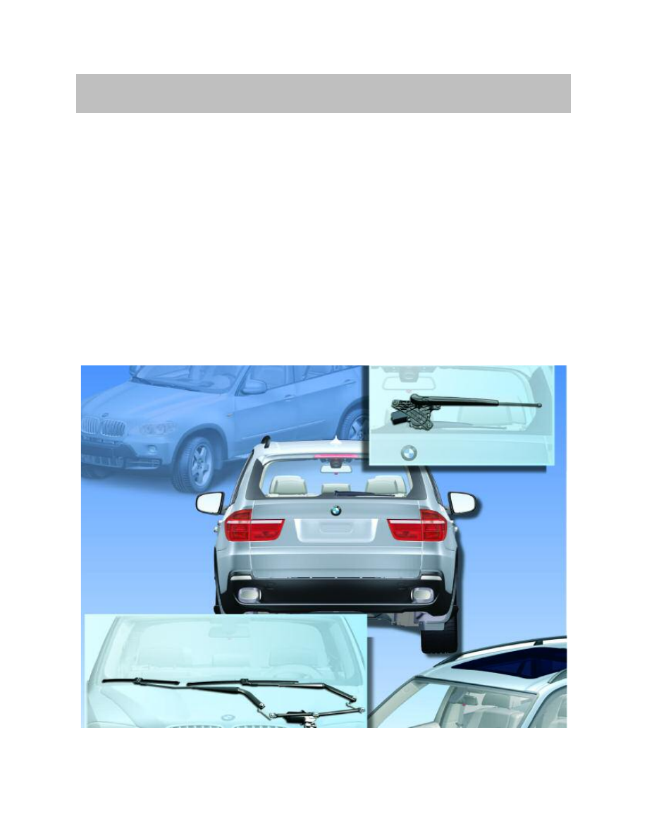
The E70 is equipped with two Windshield wipers and one rear window wiper as
standard.
The wiper function is possible in the following modes:
• Intermittent wipe
• Continuous wipe in Stage 1
• Continuous wipe in Stage 2
• Flick wipe
The E70 can be optionally equipped with headlight washer system option 502.
It is equipped with rain/driving lights/solar sensor and heated nozzles as standard.
The wipe/wash system on the E70 is a conventional wipe/wash system.
This means that the wiper motors are equipped with a reset contact.

Rain/Driving Lights/Solar Sensor
A new rain/driving lights/solar sensor is used on the E70. What is actually new is the fact
that the solar sensor has been integrated in the rain/driving lights/solar sensor. The func-
tionality of the rain sensor and of the driving lights sensor has been retained in full. This
means the driver is still assisted in that the rain sensor automatically initiates the proce-
dure for switching on the Windshield wipers.
The driving lights sensor supplies the ON signal for the driving lights control function.
Under unfavorable light conditions such as twilight or when driving through a tunnel,
the ON signal ensures the driving lights are switched on automatically. The solar sensor
makes sure the automatic climate control system provides optimum air conditioning
distribution in the vehicle.
5
E70 Wipe/wash System
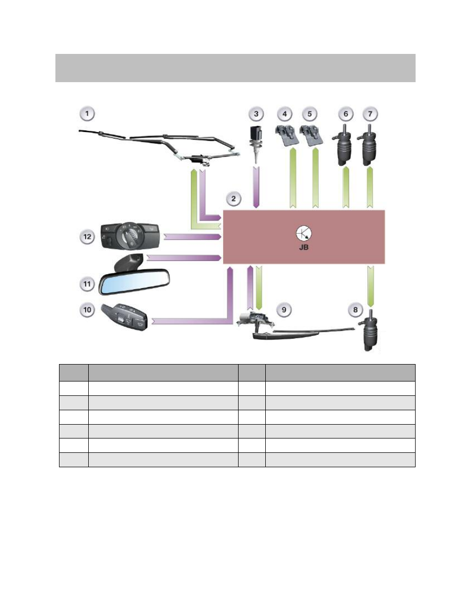
Inputs/Outputs
The front wiper motor (1) or the rear wiper motor (9) is switched on or off by correspond-
ingly operating the wiper switch on the steering column stalk (10). The junction box con-
trol unit (2) executes the functions of the wipe/wash system. The junction box control
unit also switches the washer fluid pumps (6 or 7) on or off. On vehicles equipped with
the driving lights control function, the junction box control unit receivers the information
to switch the wipe/wash system on and off from the rain/driving lights/solar sensor (11).
6
E70 Wipe/wash System
System Overview
Index
Explanation
Index
Explanation
1
Front wiper motor
7
Motor, headlight washer
2
Junction box control unit JB
8
Motor for washer fluid pump, rear
3
Outside temperature
9
Wiper motor, rear
4
Heated water jet, driver's side
10
Steering column switch, wipers
5
Heated water jet, front passenger's side
11
Rain/driving lights/solar sensor
6
Motor, washer fluid pump, front
12
Lights operating unit
System Circuit Diagram
7
E70 Wipe/wash System

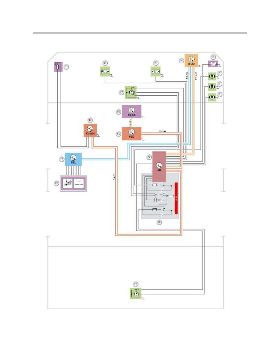
Legend for System Circuit Diagram
The signal produced when the wiper switch on the steering column stalk (12) is operated
is sent from the steering column switch cluster SZL (13) via the chassis CAN to the
dynamic stability control DSC (4). The dynamic stability control transfers the signal on to
the PT-CAN. The junction box control unit (9) switches on the wiper motor (17), for
instance, and monitors its operation.
The junction box control unit switches the washer fluid pumps (6 to 8) on or off.
On vehicles equipped with the driving lights control function, the rain-driving lights-solar
sensor (16) sends, for example, the request to switch on the wiper motor (17) via the LIN
bus. The roof functions center (15) makes the request available on the K-CAN. In this
way, the junction box control unit receives the information to switch the wiper motor on
or off.
The wipe function is dependent on the driving speed. The speed signal is made available
by the dynamic stability control (4) via the PT-CAN.
8
E70 Wipe/wash System
Index
Explanation
Index
Explanation
1
Outside temperature sensor
12
Steering column switch, wipers
2
Heated water jet, driver's side
13
Steering column switch cluster (SZL)
3
Heated water jet, front passenger's side
14
Instrument cluster
4
Dynamic Stability Control (DSC)
15
Roof functions center FZD
5
Washer fluid level sensor
16
Rain/driving lights/solar sensor
6
Motor, headlight washer
17
Front wiper motor
7
Motor, washer fluid pump, front
Kl. 30
Terminal 30
8
Motor for washer fluid pump, rear F-CAN
F-CAN
Chassis CAN
9
Junction box control unit JB
K-CAN
Body CAN
10
Relay in front power distribution box
PT-CAN
Powertrain CAN
11
Wiper motor, rear
LIN-Bus
LIN-bus
Involved components
The following components are involved in the wipe/wash system:
• Control units
– Steering column switch cluster
– Junction box control unit
– Instrument cluster
– Dynamic stability control
– Roof functions center
– Rain/driving lights/solar sensor
• Relays
– Relays 1 and 2 for front wiper motor
– Relay for headlight washer system
– Relay for rear wiper motor
• Wiper motor
– Front with reset contact
– Rear with rest contact
• Pump for washer fluid, front and rear
• Pump for headlight washer system
• Heated water jets
9
E70 Wipe/wash System
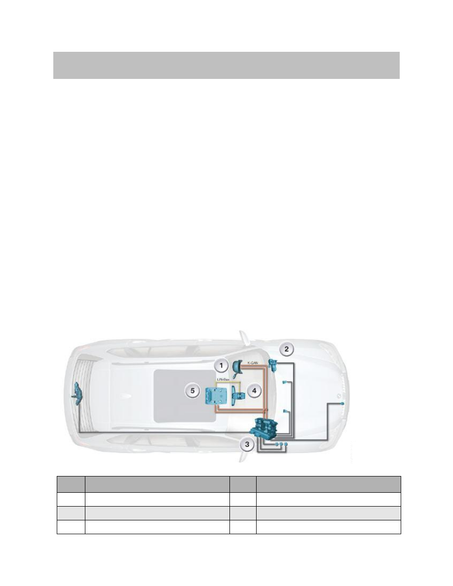
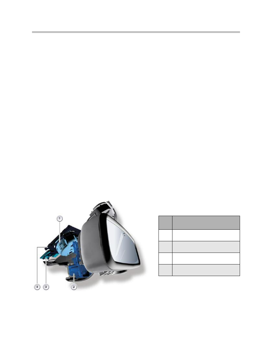
System Components
Index
Explanation
Index
Explanation
1
Steering column switch cluster
4
Rain/driving lights/solar sensor
2
Front wiper motor
5
Roof functions center
3
Junction box control unit
Control Units
Junction Box
The junction box control unit is the master for all wiper functions.
The relays for the wipe/wash functions are integrated in the front power distribution box.
The relay for the continuous wipe function in Stage 1 is plugged in and the relay for
Stage 2 soldered.
A relay each is installed in the power distribution box for wiping the rear window and for
the headlight washer system.
Roof Functions Center
The RLSS is connected to the K-CAN via the roof functions center.
Dynamic Stability Control
The dynamic stability control makes available the driving speed signal and is the interface
to the steering column switch cluster SZL.
Rain/Driving Lights/Solar Sensor
The rain/driving lights/solar sensor consists of three sensors. These sensors are:
• Rain sensor - Signal for the wipe/wash system
• Driving lights sensor - Signal for switching driving lights on and off
• Solar sensor - Signal for the air conditioning system.
Index
Explanation
1
Rain/driving lights/solar sensor
2
High beam assistant
3
Condensation sensor
4
Mounting plate
10
E70 Wipe/wash System
11
E70 Wipe/wash System
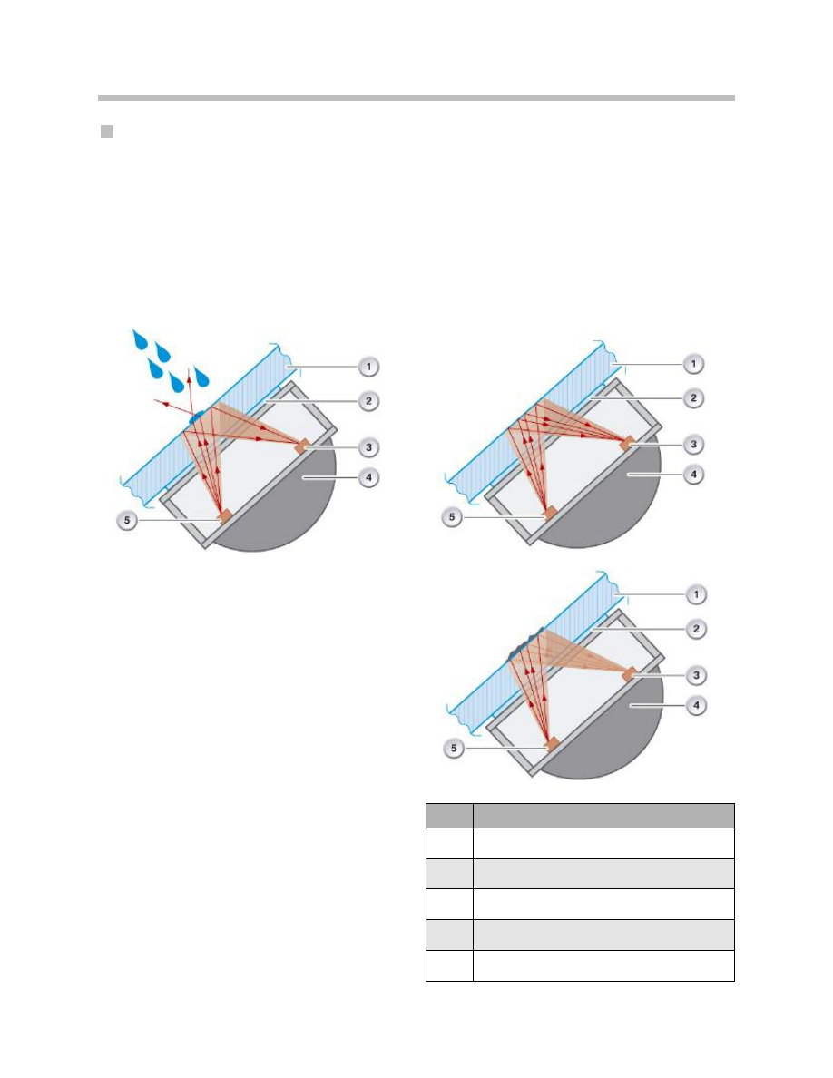
Rain Sensor
With the aid of three infrared transmit diodes and infrared receive diodes, the rain sensor
evaluates the moisture level on the Windshield.
Three rain ranges are created by combining infrared transmit diodes and infrared receive
diodes in pairs. The rain ranges are used to determine the rain intensity.
Rain detection is based on the reflection of the infrared light at the boundary surface from
the glass of the Windshield to air. The reflection is dependent on the level of soiling and
moisture on the Windshield.
The infrared light is reflected in full when the
Windshield is clean and dry.
The reflection of the infrared light is reduced
by dirt or rain water on the Windshield.
The rain sensor signals the detected rain sit-
uation to the roof functions center via the
LIN-bus. In turn, the roof functions center
transfers the information on the K-CAN. In
this way, the junction box control unit receives
the request to switch the Windshield wiper on
or off.
The signals are:
• Sensor status
• Rain intensity
• Wiper speed
• Interval period
Rain range of rain sensor E70
Index
Explanation
1
Windscreen
2
Adhesive layer
3
Infrared receive diode
4
Rain/driving lights/solar sensor
5
Infrared transmit diode
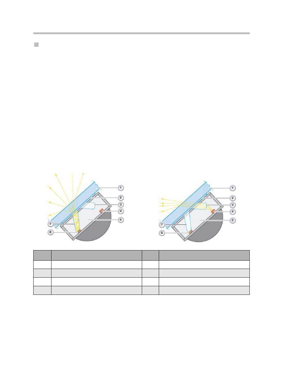
Driving Lights Sensor
The driving lights sensor registers the ambient light and the light levels in front of the
vehicle (front end). A sensor for each of these areas is integrated in the rain/driving
lights/solar sensor.
The rain/driving lights/solar sensor informs the roof functions center of the driving lights
situation via the LIN-bus, i.e. driving lights on/off and reason for switching on.
The roof functions center packs the signals into the corresponding K-CAN telegram and
sends it. In this way, the footwell module receives the request to switch the driving lights
on or off (when the automatic driving lights function is active).
The signals are:
• Status of driving lights sensor
• Status of driving lights
• Ambient brightness level
• Reason for switching on.
Ambient Light Sensor
Front End Sensor
Index
Explanation
Index
Explanation
1
Windscreen
5
Rain/driving lights/solar sensor
2
Adhesive layer
6
Infrared transmit diode
3
Light optics, front end sensor
7
Receive diode, ambient light sensor
4
Receive diode, front end sensor
12
E70 Wipe/wash System
13
E70 Wipe/wash System
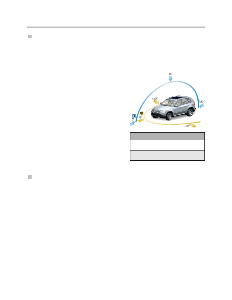
Solar Sensor
The solar sensor is assigned purely to the scope of functions of the automatic heating
and air conditioning system.
The solar sensor measures the angle of solar radiation (insolation) on to the vehicle.
The solar radiation is measured separately on the driver's and front passenger's side.
At times the solar radiation comes from the front, from the side or sometimes from the
rear due to the changes in direction while driving. The sensor there-
fore registers the solar radiation at all times.
Persons in the vehicle are subjected to these changing levels
of solar radiation (insolation). Consequently, more heat is felt
in the area of solar radiation than in the area with no solar
radiation.
The solar sensor measures the solar radiation on to
the vehicle depending on the position of the car
with respect to the sun.
The values from the solar enable the integrated
automatic heating and air conditioning system (cli-
mate control) to respond accordingly and create a
pleasant climate in the vehicle. The roof functions
center receives the values from the solar sensor
via the LIN-bus and forwards the values on the K-
CAN to the integrated automatic heating and air
conditioning system (climate control).
RLSS Variants
Two versions of the rain/driving lights/solar sensor are used in the E70. The version
depends on whether a head-up display is installed in the vehicle or not. The optics in
the front end light sensor that are pervious to infrared light are replaced by clear optics
for the head-up display.
The front end light sensor is directed at the area of the road which is also used for the
head-up display. The brightness level of the representation in the head-up display can
thus be adapted to the light situation.
This is necessary for example when driving through a tunnel with the head-up display
switched on.
Installation of the rain/driving lights/solar sensor in the E70 requires the installation of the
roof functions center with maximum equipment configuration. Consequently, the maxi-
mum equipment configuration of the interior lighting system is also installed.
Note: The rain/driving lights/solar sensor can best be distinguished simply by
looking at the Windshield. If the rain/driving lights/solar sensor has two
clear lenses then it is for the head-up display.
Index
Explanation
q
(Theta)
Angle of incidence of
solar radiation
j
(Phi)
Course of the sun from
sunrise to sunset

Three variants of the cover cap on the base of the interior rear-view mirror are possible.
• Cover without rain/driving lights/solar sensor
• Cover with rain/driving lights/solar sensor
• Cover with rain/driving lights/solar sensor and high beam assistant.
The optical element and the electronics of the rain/driving lights/solar sensor can be
replaced separately.
Note: An exception is the rain/driving lights/solar sensor for the head-up
display. This rain/driving lights/solar sensor can be replaced only as a
complete unit. The reason for this is that the optical element and the
electronics need to be matched (calibrated) in the sensor for the
head-up display. This is currently possible only as part of the
rain/driving lights/solar sensor manufacturing process.
The occurrence of small bubbles on the silicon gel layer (adhesive layer) is OK (permitted)
when replacing the optical element. Please remember to initialize the rain/driving
lights/solar sensor.
Wiper Switch
The wiper switch with the following functions is located in the steering column switch
cluster:
• Intermittent wipe
• Stage 1 and Stage 2
• Rear window wipe
• Windshield washer
• Rear window wash
• Switch for rain/driving lights/solar sensor
• Indicator for active rain/driving lights/solar sensor
The wiper switch is designed as an optical switch. The functions of the optical switch are
described in the section entitled "Steering column switch cluster".
The interval switch is a four-stage switch.
Each stage switch produces different input values in the steering column switch cluster
SZL. The input values are evaluated, for example, for setting the sensitivity of the rain/dri-
ving lights/solar sensor.
The button for the rain/driving lights/solar sensor is designed as a ground-switching but-
ton. It is required to switch on the rain/driving lights/solar sensor. The LED is illuminated
when the rain/driving lights/solar sensor is activated.
14
E70 Wipe/wash System
15
E70 Wipe/wash System
Front Wiper Motor
The front wiper motor is designed for two speed stages and has a reset contact.
Rear Wiper Motor
The rear wiper motor also features a reset contact and has one sped stage.
The purpose of the reset contact is to detect the parked (rest) position of the wiper blade.
Pump for Windshield Washer
The washer fluid pumps for washing the Windshield and rear window are mounted on the
washer fluid reservoir. These two pumps are driven directly by the junction box control
unit.
Pump for Headlight Washer
A high pressure pump is used for the headlight washer system. The pump is activated via
a relay in the front power distribution box.
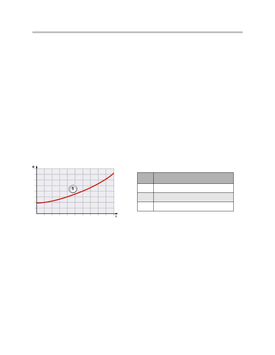
Heated Water Jets
Two heated water jets are used for the Windshield washer. The water jets feature a PTC
resistor that limits the current intake itself.
Characteristic of a PTC Resistor
Index
Explanation
1
Characteristic of a resistor
R
Resistance
t
Time

16
E70 Wipe/wash System
The wiper/washer system is switched on and off with the wiper switch. The wiper switch
is an integral part of the steering column switch cluster SZL.
Wiper Switch
The following functions are switched on with the wiper switch:
• Intermittent wipe without the rain/driving lights/solar sensor
• Automatic wipe with rain/driving lights/solar sensor
• Continuous wipe, Stage 1
• Continuous wipe, Stage 2
• Flick wipe
• Wash Windshield
• Wipe rear window
• Wash rear window
The signals of the wipe switch are sent from the steering column switch cluster via the
F-CAN to the dynamic stability control. The signal is then transferred from the dynamic
stability control via the PT-CAN to the junction box control unit. The junction box control
unit evaluates the signals and activates the wiper motor accordingly. The junction box
control unit detects the rest position (park position) of the wiper by means of the reset
contact in the wiper motor.
Windshield Wipe Function
The following functions are available for wiping the Windshield:
• Intermittent wipe in stages
• Automatic intermittent wipe
• Continuous wipe, Stage 1
• Continuous wipe, Stage 2
• Flick wipe
Intermittent Wipe
The interval can be set with the multi-stage switch. Four intermittent wipe stages are
available. The time intervals depend on the set intermittent wipe stage and the vehicle
speed. The junction box control unit calculates the time intervals and drives the wiper
motor accordingly.
Principles of Operation
Automatic Intermittent Wipe
The automatic wipe function is activated by pressing the axial button at "terminal R ON".
When active, the "automatic wipe" function is indicated by the LED on the wiper switch.
A one-off wipe function (acknowledgement wipe) is additionally started. The acknowl-
edgement wipe is also initiated when the wipe interval is increased by means of the wiper
stage switch but not when the wipe interval is decreased.
The rain/driving lights/solar sensor makes available the wipe request corresponding to the
rain intensity. The roof functions center evaluates the signal from the rain/driving
lights/solar sensor within 20 ms, transfers the relevant signal values to the corresponding
K-CAN telegram and send it cyclically (RLSS signal values unchanged) or event-
controlled (RLSS signal values changed).
The junction box control unit evaluates the request K-CAN telegram (WIPER SPEED) and
activates the wiper motor. In the automatic wipe function, the wipe speed depends on the
information from the rain/driving lights/solar sensor, i.e. continuous wipe stage 1 or stage
2 may be initiated depending on the rain intensity.
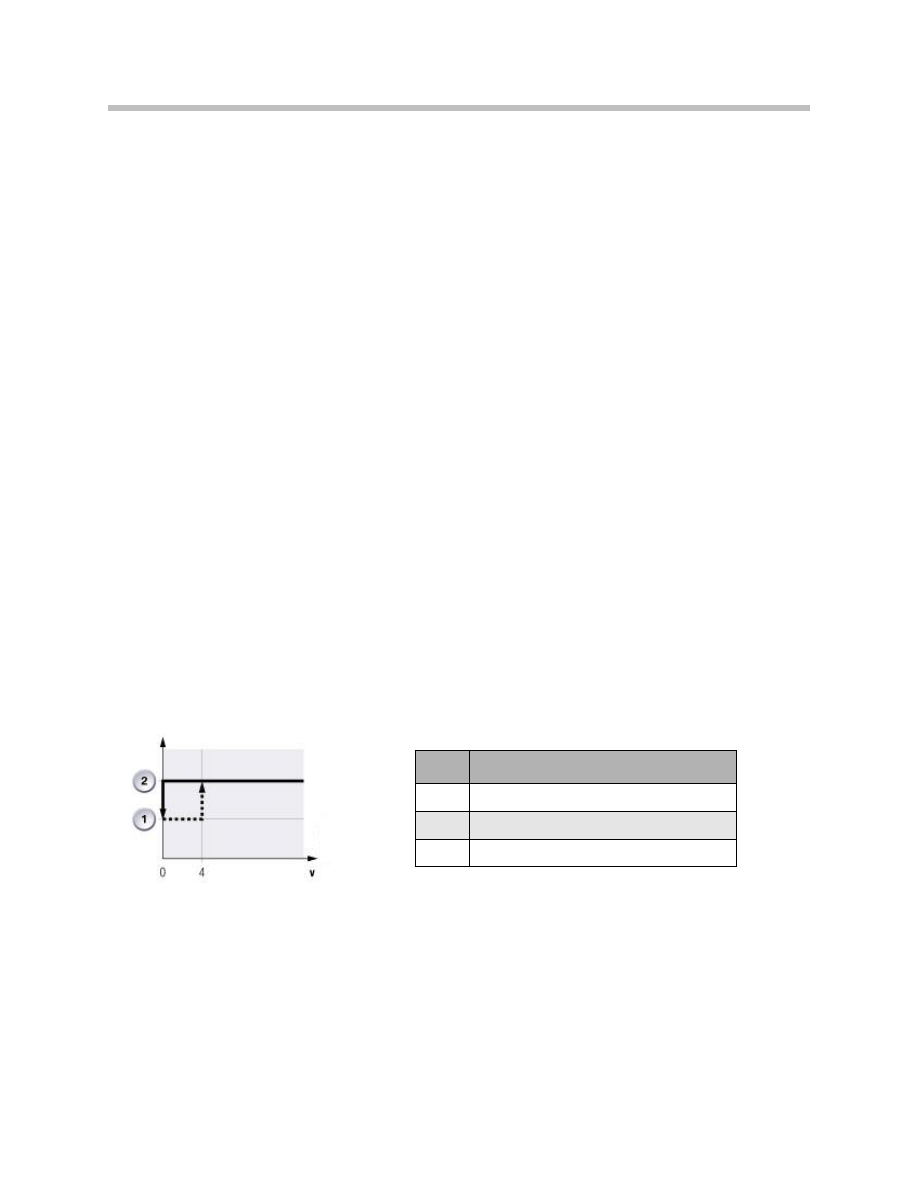
Continuous Wipe, Stage 1
The wipe motor runs at normal speed when Stage 1 is switched on with the wiper
switch. The wiper motor switches from continuous wipe in Stage 1 to intermittent wipe if
the vehicle speed is reduced down to standstill.
The continuous wipe function in Stage 1 resumes as soon as the vehicle speed is higher
than 4 km/h.
The reset (switch-back) of the wiper stage when the vehicle is stationary can be decoded.
In this case, the wiper blades operate in continuous wipe Stage 1 mode also when the
vehicle is stationary.
Index
Explanation
1
Intermittent wipe
2
Continuous wipe, Stage 1
3
Vehicle speed km/h
Decreasing Wiper Stage (continuous wipe stage 1)
17
E70 Wipe/wash System
18
E70 Wipe/wash System
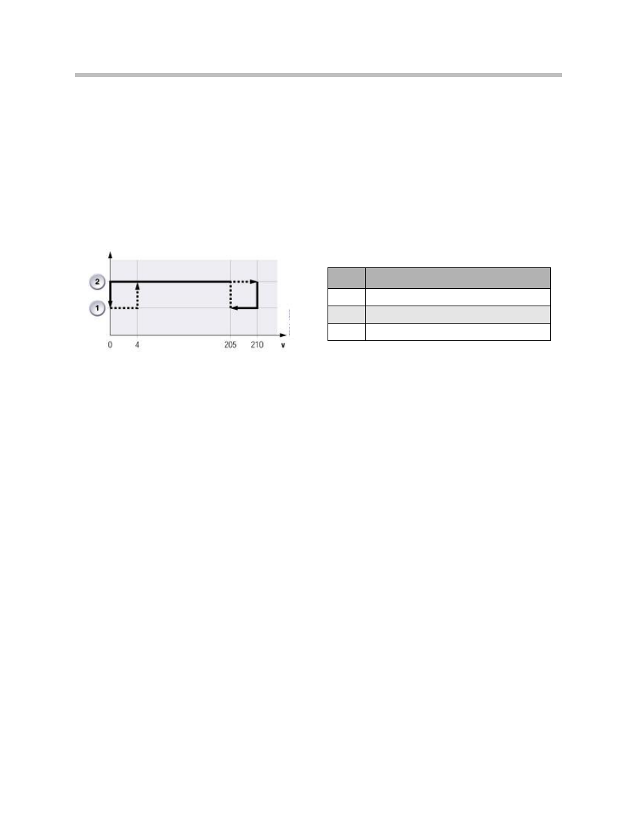
Continuous Wipe, Stage 2
The wiper blades are moved at double the speed in continuous wipe Stage 2. When the
vehicle is stationary, continuous wipe Stage 2 automatically switched back to continuous
wipe Stage 1. The wiper blades then move at normal speed. Stage 2 is resumed again at
a speed in excess of 4 km/h.
The wipe function switches back to Stage 1 at a speed in excess of 210 km/h. Stage 2 is
switched on again at a speed below 205 km/h.
The reset of the wiper stages when the vehicle is stationary can be decoded. In this case,
continuous wipe Stage 2 is retained also when the vehicle is stationary.
Single Wipe
By pressing down the wiper switch, the Single wipe function is triggered for as long as
the switch is pressed. On releasing the wiper switch, the wiper movement is completed
to the park position of the wiper blades.
Index
Explanation
1
Continuous wipe stage 1
2
Continuous wipe stage 2
3
Vehicle speed km/h
Decreasing Wiper Stage (continuous wipe stage 2)

Rear Window Wipe Function
The rear window wipe function is switched on with the wiper switch by pressing the stalk
forward. The control of the rear window wiper is integrated in the junction box control unit.
The rear window wiper features the following functions:
• Intermittent wipe
• Continuous wipe
Intermittent Wipe
The intermittent wipe function of the rear window wiper is started by pressing the wiper
switch forward. The optical signal from the steering column switch is evaluated by the
steering column switch cluster. The steering column switch cluster sends the signal on
the F-CAN to the dynamic stability control.
From the dynamic stability control, the signal is made available on the PT-CAN. The junc-
tion box receives the signal and correspondingly activates the rear window wiper. The
junction box control unit detects the rest position (park position) of the rear window wiper
by means of the reset contact in the wiper motor.
Continuous Wipe
The rear window wiper switches over to continuous wipe when reverse gear is engaged.
Operation of the rear window wiper is not stopped when the rear hatch is opened.
Front and Rear Antiblocking Function
The Windshield wipers and the rear window wiper feature the antiblocking function which
is integrated in the junction box control unit. If the signal is not sent from the reset contact
while the wiper motor is running, this is interpreted as a blocking situation.
The junction box control unit evaluates the signal from the reset contact for the antiblock-
ing function. The junction box control unit switches off the blocking motor. A further
attempt can be made to switch on the wiper. If the wiper blocks again, it will no longer be
operative for approximately. 3 minutes. The wiper inhibit is cancelled by changing from
"terminal R ON" to "terminal R OFF" and "terminal R ON". The wiper must then be
switched on again.
Wash Functions
The E70 has a wash function for the Windshield and the rear window. The function is
operated via the wiper switch.
Wash Windshield
On pulling the wiper switch, initially the washer fluid pump is switched on followed by the
Windshield wiper. The washer fluid pump remains switched on for as long as the wiper
switch is pulled.
19
E70 Wipe/wash System

20
E70 Wipe/wash System
The signal is routed from the steering column switch cluster to the junction box control
unit. The junction box control unit activates the washer fluid pump directly.
After the pump is switched off, the wipers continue to operate for several wipe cycles in
order to wipe the Windshield dry. The wipe function set before the Windshield wash cycle
is continued after the Windshield has been washed.
The junction box control unit will no longer drive the washer fluid pump if the fluid level in
the washer fluid reservoir is too low. The junction box control unit receives the information
necessary for this purpose from the washer fluid level sensor.
Washer Fluid Level Sensor
The junction box control unit monitors the washer fluid level sensor as from "terminal R
ON". The washer fluid level sensor switches to ground.
The junction box control unit receives a low signal when the washer fluid reservoir is full.
The switch opens when the fluid level in the washer fluid reservoir drops below a certain
level. The low signal changes to a high signal. The junction box control unit consequently
generates a message indicating the low level in the washer fluid reservoir.
Rear Window Wash Function
The rear window wash function is started by pressing the wiper switch forward. Initially,
the washer fluid pump for the rear window is activated, followed by the rear window wiper
switching on. The wipe function set before the start of the wash cycle and after the end
of the wash function is continued again.
Terminal 50
The washer function is interrupted or not at all started while the vehicle is started.
If the Windshield washer function was interrupted, the started function is continued after
the vehicle start procedure has been completed.
Headlight Washer System
The headlight washer system is switched on during the first wash cycle after "terminal R
ON" and "lights ON". Activation is then suppressed for 7 minutes. The headlight washer
system is activated if the Windshield washer system is operated 5 times within the 7 min-
utes.
In response to the request from the junction box control unit, the headlight washer sys-
tem is switched on by means of a relay in the junction box.
The headlight washer system is no longer activated if the washer fluid level in the washer
fluid reservoir is too low. The junction box control unit receives the corresponding signal
from the washer fluid level sensor.
The headlight washer system is also not activated when blocking of the wipers is detect-
ed.

Emergency Operating Functions
SZL Failure
The wipers can no longer be operated in the event of the steering column switch cluster
failing or a break in the bus connection. The junction box control unit switches to emer-
gency operating mode and the Windshield wipers are switched on in Stage 1 setting.
RLSS Failure
If there is a fault in the rain/driving lights/solar sensor or it fails completely, the junction
box control unit takes over control of the wipe/wash system and assumes emergency
operating mode. Emergency operating mode is an intermittent wipe function that is
dependent on the vehicle speed.
Replacing the RLSS
The following steps are necessary after replacing the sensor:
• Encode rain/driving lights/solar sensor
• Clear fault code memory
• Initialize rain/driving lights/solar sensor.
Service Information
21
E70 Wipe/wash System
Document Outline
- Main Menu
- E70 Introduction
- E70 Glovebox
- E70 Powertrain
- E70 Gasoline Engines
- E70 Transmissions
- E70 Voltage Supply and Bus Systems
- E70 Car Access System 3
- E70 Energy Management
- E70 Chassis Dynamics
- E70 Lateral Dynamics Systems
- E70 Vertical Dynamics Systems
- E70 Longitudinal Dynamics Systems
- E70 Central Locking
- E70 Power Windows
- E70 Comfort Access
- E70 Wipe/Wash System
- E70 Panorama Glass Sunroof
- E70 Seats
- E70 Automatic Tailgate
- E70 Steering Column Switch Cluster
- E70 Exterior Lighting
- E70 Interior Lighting
- E70 Adaptive Headlight System
- E70 Park Distance Control
- E70 Rear-view Camera
- E70 Anti-Theft Alarm System
- E70 Outside Mirrors
- E70 Displays Indicators and Controls
- E70 Head-up Display
- E70 Information and Communication
- E70 Audio Systems
- E70 Rear Seat Entertainment
- E70 Climate Control Systems
- E70 Passive Safety Systems
Wyszukiwarka
Podobne podstrony:
04b E70 Lateral Dynamics Systems
05b4 E70 Adaptive Headlight System
03b E70 Car Access System 3
04d E70 Longitudinal Dynamics Systems
09 E70 Passive Safety Systems
16 E70 Audio Systems
07b E70 Audio Systems
07 E70 Audio Systems WB
05c3 E70 Anti Theft Alarm System
System finansowy w Polsce 2
Systemy operacyjne
Systemy Baz Danych (cz 1 2)
Współczesne systemy polityczne X
System Warset na GPW w Warszawie
003 zmienne systemowe
elektryczna implementacja systemu binarnego
09 Architektura systemow rozproszonychid 8084 ppt
SYSTEMY EMERYTALNE
więcej podobnych podstron