
1
Instruction Set Nomenclature
Status Register (SREG)
SREG:
Status Register
C:
Carry Flag
Z:
Zero Flag
N:
Negative Flag
V:
Two’s complement overflow indicator
S:
N
⊕
V, For signed tests
H:
Half Carry Flag
T:
Transfer bit used by BLD and BST instructions
I:
Global Interrupt Enable/Disable Flag
Registers and Operands
Rd:
Destination (and source) register in the Register File
Rr:
Source register in the Register File
R:
Result after instruction is executed
K:
Constant data
k:
Constant address
b:
Bit in the Register File or I/O Register (3-bit)
s:
Bit in the Status Register (3-bit)
X,Y,Z:
Indirect Address Register
(X=R27:R26, Y=R29:R28 and Z=R31:R30)
A:
I/O location address
q:
Displacement for direct addressing (6-bit)
8-bit
Instruction Set
Rev. 0856D–AVR–08/02

2
AVR Instruction Set
0856D–AVR–08/02
I/O Registers
RAMPX, RAMPY, RAMPZ
Registers concatenated with the X-, Y-, and Z-registers enabling indirect addressing of the whole data space on MCUs with
more than 64K bytes data space, and constant data fetch on MCUs with more than 64K bytes program space.
RAMPD
Register concatenated with the Z-register enabling direct addressing of the whole data space on MCUs with more than 64K
bytes data space.
EIND
Register concatenated with the instruction word enabling indirect jump and call to the whole program space on MCUs with
more than 64K bytes program space.
Stack
STACK: Stack for return address and pushed registers
SP:
Stack Pointer to STACK
Flags
⇔
:
Flag affected by instruction
0:
Flag cleared by instruction
1:
Flag set by instruction
-:
Flag not affected by instruction
3
AVR Instruction Set
0856D–AVR–08/02
The Program and Data Addressing Modes
The AVR Enhanced RISC microcontroller supports powerful and efficient addressing modes for access to the Program
memory (Flash) and Data memory (SRAM, Register file, I/O Memory, and Extended I/O Memory). This section describes
the various addressing modes supported by the AVR architecture. In the following figures, OP means the operation code
part of the instruction word. To simplify, not all figures show the exact location of the addressing bits. To generalize, the
abstract terms RAMEND and FLASHEND have been used to represent the highest location in data and program space,
respectively.
Note:
Not all addressing modes are present in all devices. Refer to the device spesific instruction summary.
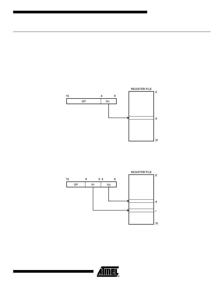
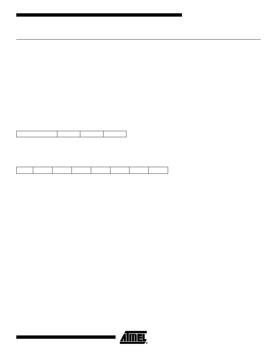
Register Direct, Single Register Rd
Figure 1. Direct Single Register Addressing
The operand is contained in register d (Rd).
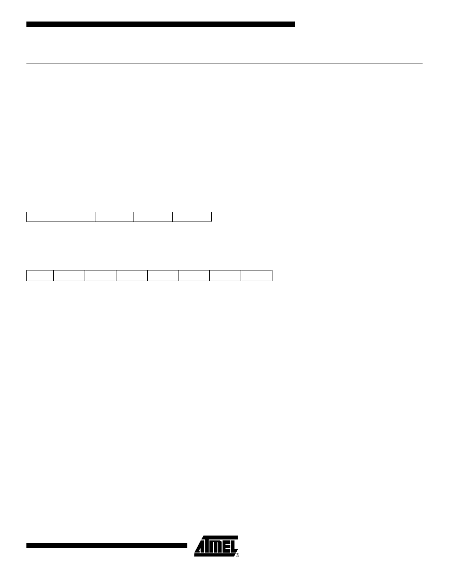
Register Direct, Two Registers Rd and Rr
Figure 2. Direct Register Addressing, Two Registers
Operands are contained in register r (Rr) and d (Rd). The result is stored in register d (Rd).
4
AVR Instruction Set
0856D–AVR–08/02
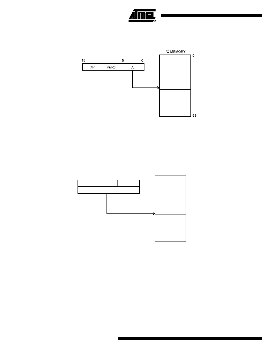
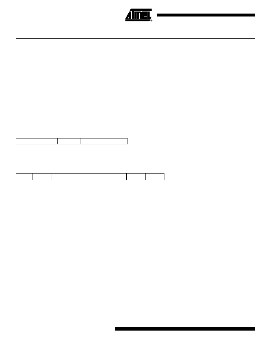
I/O Direct
Figure 3. I/O Direct Addressing
Operand address is contained in 6 bits of the instruction word. n is the destination or source register address.
Note:
Some complex AVR Microcontrollers have more peripheral units than can be supported within the 64 locations reserved in the
opcode for I/O direct addressing. The extended I/O memory from address 64 to 255 can only be reached by data addressing,
not I/O addressing.
Data Direct
Figure 4. Direct Data Addressing
A 16-bit Data Address is contained in the 16 LSBs of a two-word instruction. Rd/Rr specify the destination or source
register.
OP
Rr/Rd
16
31
15
0
Data Address
0x0000
RAMEND
20 19
Data Space
5
AVR Instruction Set
0856D–AVR–08/02
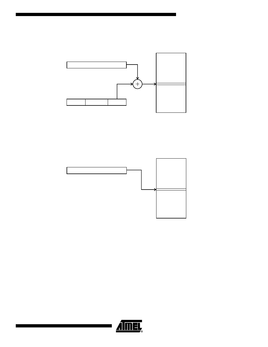
Data Indirect with Displacement
Figure 5. Data Indirect with Displacement
Operand address is the result of the Y- or Z-register contents added to the address contained in 6 bits of the instruction
word. Rd/Rr specify the destination or source register.
Data Indirect
Figure 6. Data Indirect Addressing
Operand address is the contents of the X-, Y-, or the Z-register. In AVR devices without SRAM, Data Indirect Addressing is
called Register Indirect Addressing. Register Indirect Addressing is a subset of Data Indirect Addressing since the data
space form 0 to 31 is the Register File.
Data Space
0x0000
RAMEND
Y OR Z - REGISTER
OP
q
Rr/Rd
0
0
5
6
10
15
15
Data Space
0x0000
X, Y OR Z - REGISTER
0
15
RAMEND
6
AVR Instruction Set
0856D–AVR–08/02
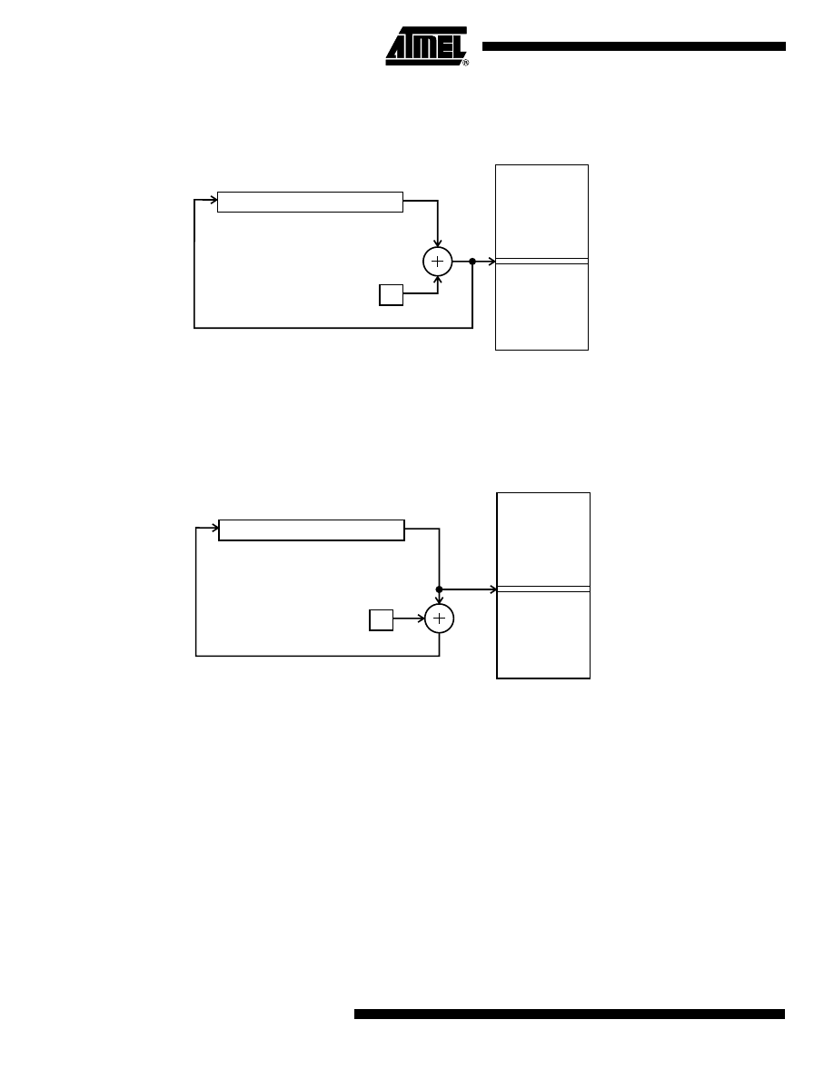
Data Indirect with Pre-decrement
Figure 7. Data Indirect Addressing with Pre-decrement
The X,- Y-, or the Z-register is decremented before the operation. Operand address is the decremented contents of the X-,
Y-, or the Z-register.
Data Indirect with Post-increment
Figure 8. Data Indirect Addressing with Post-increment
The X-, Y-, or the Z-register is incremented after the operation. Operand address is the content of the X-, Y-, or the Z-regis-
ter prior to incrementing.
Data Space
0x0000
X, Y OR Z - REGISTER
0
15
-1
RAMEND
Data Space
0x0000
X, Y OR Z - REGISTER
0
15
1
RAMEND
7
AVR Instruction Set
0856D–AVR–08/02
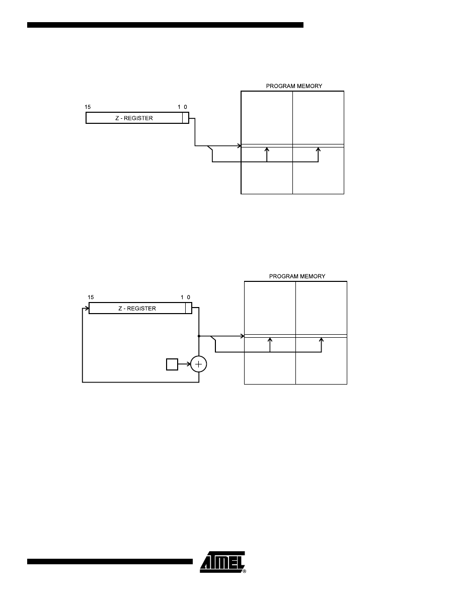
Program Memory Constant Addressing using the LPM, ELPM, and SPM Instructions
Figure 9. Program Memory Constant Addressing
Constant byte address is specified by the Z-register contents. The 15 MSBs select word address. For LPM, the LSB selects
low byte if cleared (LSB = 0) or high byte if set (LSB = 1). For SPM, the LSB should be cleared. If ELPM is used, the
RAMPZ Register is used to extend the Z-register.
Program Memory with Post-increment using the LPM Z+ and ELPM Z+ Instruction
Figure 10. Program Memory Addressing with Post-increment
Constant byte address is specified by the Z-register contents. The 15 MSBs select word address. The LSB selects low byte
if cleared (LSB = 0) or high byte if set (LSB = 1). If ELPM Z+ is used, the RAMPZ Register is used to extend the Z-register.
FLASHEND
0x0000
LSB
FLASHEND
0x0000
1
LSB
8
AVR Instruction Set
0856D–AVR–08/02
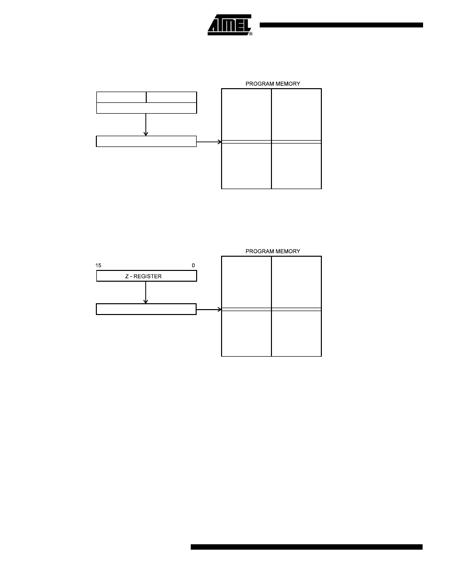
Direct Program Addressing, JMP and CALL
Figure 11. Direct Program Memory Addressing
Program execution continues at the address immediate in the instruction word.
Indirect Program Addressing, IJMP and ICALL
Figure 12. Indirect Program Memory Addressing
Program execution continues at address contained by the Z-register (i.e., the PC is loaded with the contents of the Z-
register).
FLASHEND
31
16
OP
6 MSB
16 LSB
PC
21
0
15
0
0x0000
FLASHEND
PC
15
0
0x0000
9
AVR Instruction Set
0856D–AVR–08/02
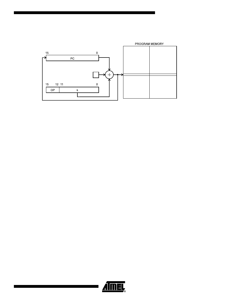
Relative Program Addressing, RJMP and RCALL
Figure 13. Relative Program Memory Addressing
Program execution continues at address PC + k + 1. The relative address k is from -2048 to 2047.
FLASHEND
1
0x0000

10
AVR Instruction Set
0856D–AVR–08/02
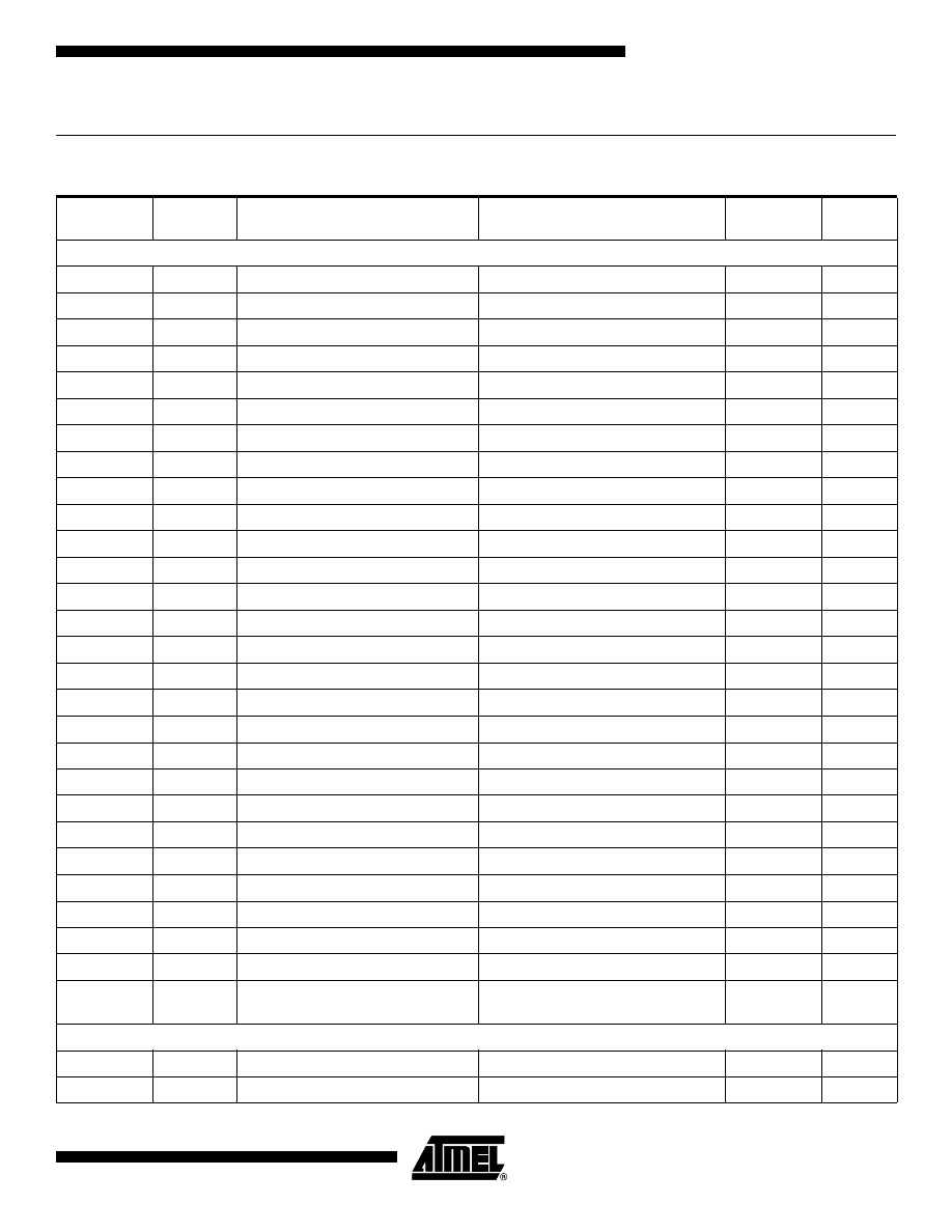
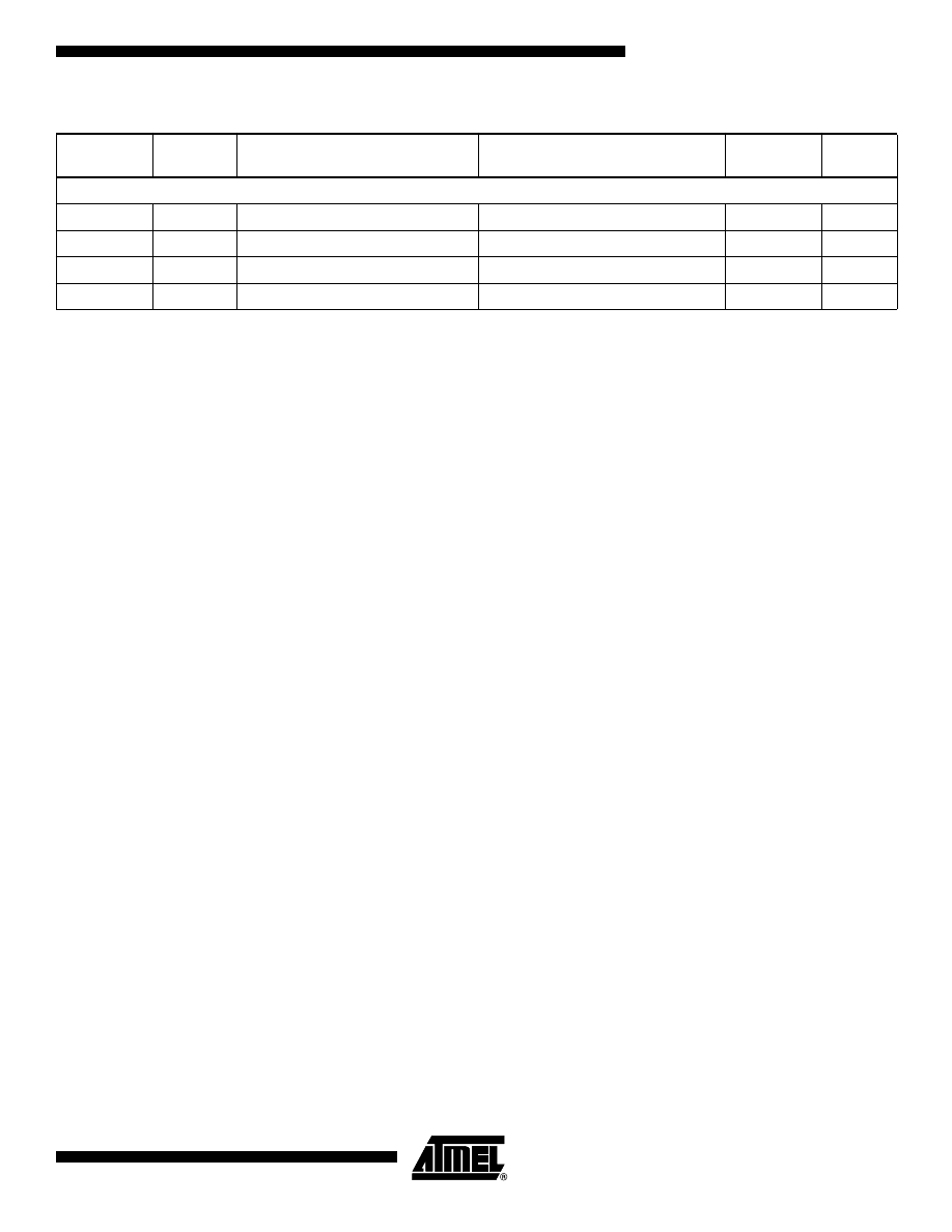
Conditional Branch Summary
Note:
1. Interchange Rd and Rr in the operation before the test, i.e., CP Rd,Rr
→
CP Rr,Rd
Test
Boolean
Mnemonic
Complementary
Boolean
Mnemonic
Comment
Rd > Rr
Z
•
(N
⊕
V) = 0
BRLT
Rd
≤
Rr
Z+(N
⊕
V) = 1
BRGE*
Signed
Rd
≥
Rr
(N
⊕
V) = 0
BRGE
Rd < Rr
(N
⊕
V) = 1
BRLT
Signed
Rd = Rr
Z = 1
BREQ
Rd
≠
Rr
Z = 0
BRNE
Signed
Rd
≤
Rr
Z+(N
⊕
V) = 1
BRGE
Rd > Rr
Z
•
(N
⊕
V) = 0
BRLT*
Signed
Rd < Rr
(N
⊕
V) = 1
BRLT
Rd
≥
Rr
(N
⊕
V) = 0
BRGE
Signed
Rd > Rr
C + Z = 0
BRLO
Rd
≤
Rr
C + Z = 1
BRSH*
Unsigned
Rd
≥
Rr
C = 0
BRSH/BRCC
Rd < Rr
C = 1
BRLO/BRCS
Unsigned
Rd = Rr
Z = 1
BREQ
Rd
≠
Rr
Z = 0
BRNE
Unsigned
Rd
≤
Rr
C + Z = 1
BRSH
Rd > Rr
C + Z = 0
BRLO*
Unsigned
Rd < Rr
C = 1
BRLO/BRCS
Rd
≥
Rr
C = 0
BRSH/BRCC
Unsigned
Carry
C = 1
BRCS
No carry
C = 0
BRCC
Simple
Negative
N = 1
BRMI
Positive
N = 0
BRPL
Simple
Overflow
V = 1
BRVS
No overflow
V = 0
BRVC
Simple
Zero
Z = 1
BREQ
Not zero
Z = 0
BRNE
Simple
11
AVR Instruction Set
0856D–AVR–08/02
Complete Instruction Set Summary
Instruction Set Summary
Mnemonics
Operands
Description
Operation
Flags
#Clock
Note
Arithmetic and Logic Instructions
ADD
Rd, Rr
Add without Carry
Rd
←
Rd + Rr
Z,C,N,V,S,H
1
ADC
Rd, Rr
Add with Carry
Rd
←
Rd + Rr + C
Z,C,N,V,S,H
1
ADIW
Rd, K
Add Immediate to Word
Rd+1:Rd
←
Rd+1:Rd + K
Z,C,N,V,S
2
SUB
Rd, Rr
Subtract without Carry
Rd
←
Rd - Rr
Z,C,N,V,S,H
1
SUBI
Rd, K
Subtract Immediate
Rd
←
Rd - K
Z,C,N,V,S,H
1
SBC
Rd, Rr
Subtract with Carry
Rd
←
Rd - Rr - C
Z,C,N,V,S,H
1
SBCI
Rd, K
Subtract Immediate with Carry
Rd
←
Rd - K - C
Z,C,N,V,S,H
1
SBIW
Rd, K
Subtract Immediate from Word
Rd+1:Rd
←
Rd+1:Rd - K
Z,C,N,V,S
2
AND
Rd, Rr
Logical AND
Rd
←
Rd
•
Rr
Z,N,V,S
1
ANDI
Rd, K
Logical AND with Immediate
Rd
←
Rd
•
K
Z,N,V,S
1
OR
Rd, Rr
Logical OR
Rd
←
Rd v Rr
Z,N,V,S
1
ORI
Rd, K
Logical OR with Immediate
Rd
←
Rd v K
Z,N,V,S
1
EOR
Rd, Rr
Exclusive OR
Rd
←
Rd
⊕
Rr
Z,N,V,S
1
COM
Rd
One’s Complement
Rd
←
$FF - Rd
Z,C,N,V,S
1
NEG
Rd
Two’s Complement
Rd
←
$00 - Rd
Z,C,N,V,S,H
1
SBR
Rd,K
Set Bit(s) in Register
Rd
←
Rd v K
Z,N,V,S
1
CBR
Rd,K
Clear Bit(s) in Register
Rd
←
Rd
•
($FFh - K)
Z,N,V,S
1
INC
Rd
Increment
Rd
←
Rd + 1
Z,N,V,S
1
DEC
Rd
Decrement
Rd
←
Rd - 1
Z,N,V,S
1
TST
Rd
Test for Zero or Minus
Rd
←
Rd
•
Rd
Z,N,V,S
1
CLR
Rd
Clear Register
Rd
←
Rd
⊕
Rd
Z,N,V,S
1
SER
Rd
Set Register
Rd
←
$FF
None
1
MUL
Rd,Rr
Multiply Unsigned
R1:R0
←
Rd
×
Rr (UU)
Z,C
2
MULS
Rd,Rr
Multiply Signed
R1:R0
←
Rd
×
Rr (SS)
Z,C
2
MULSU
Rd,Rr
Multiply Signed with Unsigned
R1:R0
←
Rd
×
Rr (SU)
Z,C
2
FMUL
Rd,Rr
Fractional Multiply Unsigned
R1:R0
←
(Rd
×
Rr)<<1 (UU)
Z,C
2
FMULS
Rd,Rr
Fractional Multiply Signed
R1:R0
←
(Rd
×
Rr)<<1 (SS)
Z,C
2
FMULSU
Rd,Rr
Fractional Multiply Signed with
Unsigned
R1:R0
←
(Rd
×
Rr)<<1 (SU)
Z,C
2
Branch Instructions
RJMP
k
Relative Jump
PC
←
PC + k + 1
None
2
IJMP
Indirect Jump to (Z)
PC(15:0)
←
Z, PC(21:16)
←
0
None
2

12
AVR Instruction Set
0856D–AVR–08/02
EIJMP
Extended Indirect Jump to (Z)
PC(15:0)
←
Z, PC(21:16)
←
EIND
None
2
JMP
k
Jump
PC
←
k
None
3
RCALL
k
Relative Call Subroutine
PC
←
PC + k + 1
None
3 / 4
ICALL
Indirect Call to (Z)
PC(15:0)
←
Z, PC(21:16)
←
0
None
3 / 4
EICALL
Extended Indirect Call to (Z)
PC(15:0)
←
Z, PC(21:16)
←
EIND
None
4
CALL
k
Call Subroutine
PC
←
k
None
4 / 5
RET
Subroutine Return
PC
←
STACK
None
4 / 5
RETI
Interrupt Return
PC
←
STACK
I
4 / 5
CPSE
Rd,Rr
Compare, Skip if Equal
if (Rd = Rr) PC
←
PC + 2 or 3
None
1 / 2 / 3
CP
Rd,Rr
Compare
Rd - Rr
Z,C,N,V
,S
,H
1
CPC
Rd,Rr
Compare with Carry
Rd - Rr - C
Z,C,N,V
,S
,H
1
CPI
Rd,K
Compare with Immediate
Rd - K
Z,C,N,V
,S
,H
1
SBRC
Rr, b
Skip if Bit in Register Cleared
if (Rr(b)=0) PC
←
PC + 2 or 3
None
1 / 2 / 3
SBRS
Rr, b
Skip if Bit in Register Set
if (Rr(b)=1) PC
←
PC + 2 or 3
None
1 / 2 / 3
SBIC
A, b
Skip if Bit in I/O Register Cleared
if(I/O(A,b)=0) PC
←
PC + 2 or 3
None
1 / 2 / 3
SBIS
A, b
Skip if Bit in I/O Register Set
If(I/O(A,b)=1) PC
←
PC + 2 or 3
None
1 / 2 / 3
BRBS
s, k
Branch if Status Flag Set
if (SREG(s) = 1) then PC
←
PC+k + 1
None
1 / 2
BRBC
s, k
Branch if Status Flag Cleared
if (SREG(s) = 0) then PC
←
PC+k + 1
None
1 / 2
BREQ
k
Branch if Equal
if (Z = 1) then PC
←
PC + k + 1
None
1 / 2
BRNE
k
Branch if Not Equal
if (Z = 0) then PC
←
PC + k + 1
None
1 / 2
BRCS
k
Branch if Carry Set
if (C = 1) then PC
←
PC + k + 1
None
1 / 2
BRCC
k
Branch if Carry Cleared
if (C = 0) then PC
←
PC + k + 1
None
1 / 2
BRSH
k
Branch if Same or Higher
if (C = 0) then PC
←
PC + k + 1
None
1 / 2
BRLO
k
Branch if Lower
if (C = 1) then PC
←
PC + k + 1
None
1 / 2
BRMI
k
Branch if Minus
if (N = 1) then PC
←
PC + k + 1
None
1 / 2
BRPL
k
Branch if Plus
if (N = 0) then PC
←
PC + k + 1
None
1 / 2
BRGE
k
Branch if Greater or Equal, Signed
if (N
⊕
V= 0) then PC
←
PC + k + 1
None
1 / 2
BRLT
k
Branch if Less Than, Signed
if (N
⊕
V= 1) then PC
←
PC + k + 1
None
1 / 2
BRHS
k
Branch if Half Carry Flag Set
if (H = 1) then PC
←
PC + k + 1
None
1 / 2
BRHC
k
Branch if Half Carry Flag Cleared
if (H = 0) then PC
←
PC + k + 1
None
1 / 2
BRTS
k
Branch if T Flag Set
if (T = 1) then PC
←
PC + k + 1
None
1 / 2
BRTC
k
Branch if T Flag Cleared
if (T = 0) then PC
←
PC + k + 1
None
1 / 2
BRVS
k
Branch if Overflow Flag is Set
if (V = 1) then PC
←
PC + k + 1
None
1 / 2
BRVC
k
Branch if Overflow Flag is Cleared
if (V = 0) then PC
←
PC + k + 1
None
1 / 2
BRIE
k
Branch if Interrupt Enabled
if ( I = 1) then PC
←
PC + k + 1
None
1 / 2
Instruction Set Summary (Continued)
Mnemonics
Operands
Description
Operation
Flags
#Clock
Note

13
AVR Instruction Set
0856D–AVR–08/02
BRID
k
Branch if Interrupt Disabled
if ( I = 0) then PC
←
PC + k + 1
None
1 / 2
Data Transfer Instructions
MOV
Rd, Rr
Copy Register
Rd
←
Rr
None
1
MOVW
Rd, Rr
Copy Register Pair
Rd+1:Rd
←
Rr+1:Rr
None
1
LDI
Rd, K
Load Immediate
Rd
←
K
None
1
LDS
Rd, k
Load Direct from data space
Rd
←
(k)
None
2
LD
Rd, X
Load Indirect
Rd
←
(X)
None
2
LD
Rd, X+
Load Indirect and Post-Increment
Rd
←
(X), X
←
X + 1
None
2
LD
Rd, -X
Load Indirect and Pre-Decrement
X
←
X - 1, Rd
←
(X)
None
2
LD
Rd, Y
Load Indirect
Rd
←
(Y)
None
2
LD
Rd, Y+
Load Indirect and Post-Increment
Rd
←
(Y), Y
←
Y + 1
None
2
LD
Rd, -Y
Load Indirect and Pre-Decrement
Y
←
Y - 1, Rd
←
(Y)
None
2
LDD
Rd,Y+q
Load Indirect with Displacement
Rd
←
(Y + q)
None
2
LD
Rd, Z
Load Indirect
Rd
←
(Z)
None
2
LD
Rd, Z+
Load Indirect and Post-Increment
Rd
←
(Z), Z
←
Z+1
None
2
LD
Rd, -Z
Load Indirect and Pre-Decrement
Z
←
Z - 1, Rd
←
(Z)
None
2
LDD
Rd, Z+q
Load Indirect with Displacement
Rd
←
(Z + q)
None
2
STS
k, Rr
Store Direct to data space
(k)
←
Rd
None
2
ST
X, Rr
Store Indirect
(X)
←
Rr
None
2
ST
X+, Rr
Store Indirect and Post-Increment
(X)
←
Rr, X
←
X + 1
None
2
ST
-X, Rr
Store Indirect and Pre-Decrement
X
←
X - 1, (X)
←
Rr
None
2
ST
Y, Rr
Store Indirect
(Y)
←
Rr
None
2
ST
Y+, Rr
Store Indirect and Post-Increment
(Y)
←
Rr, Y
←
Y + 1
None
2
ST
-Y, Rr
Store Indirect and Pre-Decrement
Y
←
Y - 1, (Y)
←
Rr
None
2
STD
Y+q,Rr
Store Indirect with Displacement
(Y + q)
←
Rr
None
2
ST
Z, Rr
Store Indirect
(Z)
←
Rr
None
2
ST
Z+, Rr
Store Indirect and Post-Increment
(Z)
←
Rr, Z
←
Z + 1
None
2
ST
-Z, Rr
Store Indirect and Pre-Decrement
Z
←
Z - 1, (Z)
←
Rr
None
2
STD
Z+q,Rr
Store Indirect with Displacement
(Z + q)
←
Rr
None
2
LPM
Load Program Memory
R0
←
(Z)
None
3
LPM
Rd, Z
Load Program Memory
Rd
←
(Z)
None
3
LPM
Rd, Z+
Load Program Memory and Post-
Increment
Rd
←
(Z), Z
←
Z + 1
None
3
ELPM
Extended Load Program Memory
R0
←
(RAMPZ:Z)
None
3
ELPM
Rd, Z
Extended Load Program Memory
Rd
←
(RAMPZ:Z)
None
3
Instruction Set Summary (Continued)
Mnemonics
Operands
Description
Operation
Flags
#Clock
Note

14
AVR Instruction Set
0856D–AVR–08/02
ELPM
Rd, Z+
Extended Load Program Memory
and Post-Increment
Rd
←
(RAMPZ:Z), Z
←
Z + 1
None
3
SPM
Store Program Memory
(Z)
←
R1:R0
None
-
IN
Rd, A
In From I/O Location
Rd
←
I/O(A)
None
1
OUT
A, Rr
Out To I/O Location
I/O(A)
←
Rr
None
1
PUSH
Rr
Push Register on Stack
STACK
←
Rr
None
2
POP
Rd
Pop Register from Stack
Rd
←
STACK
None
2
Bit and Bit-test Instructions
LSL
Rd
Logical Shift Left
Rd(n+1)
←
Rd(n),Rd(0)
←
0,C
←
Rd(7)
Z,C,N,V,H
1
LSR
Rd
Logical Shift Right
Rd(n)
←
Rd(n+1),Rd(7)
←
0,C
←
Rd(0)
Z,C,N,V
1
ROL
Rd
Rotate Left Through Carry
Rd(0)
←
C,Rd(n+1)
←
Rd(n),C
←
Rd(7)
Z,C,N,V,H
1
ROR
Rd
Rotate Right Through Carry
Rd(7)
←
C,Rd(n)
←
Rd(n+1),C
←
Rd(0)
Z,C,N,V
1
ASR
Rd
Arithmetic Shift Right
Rd(n)
←
Rd(n+1), n=0..6
Z,C,N,V
1
SWAP
Rd
Swap Nibbles
Rd(3..0)
↔
Rd(7..4)
None
1
BSET
s
Flag Set
SREG(s)
←
1
SREG(s)
1
BCLR
s
Flag Clear
SREG(s)
←
0
SREG(s)
1
SBI
A, b
Set Bit in I/O Register
I/O(A, b)
←
1
None
2
CBI
A, b
Clear Bit in I/O Register
I/O(A, b)
←
0
None
2
BST
Rr, b
Bit Store from Register to T
T
←
Rr(b)
T
1
BLD
Rd, b
Bit load from T to Register
Rd(b)
←
T
None
1
SEC
Set Carry
C
←
1
C
1
CLC
Clear Carry
C
←
0
C
1
SEN
Set Negative Flag
N
←
1
N
1
CLN
Clear Negative Flag
N
←
0
N
1
SEZ
Set Zero Flag
Z
←
1
Z
1
CLZ
Clear Zero Flag
Z
←
0
Z
1
SEI
Global Interrupt Enable
I
←
1
I
1
CLI
Global Interrupt Disable
I
←
0
I
1
SES
Set Signed Test Flag
S
←
1
S
1
CLS
Clear Signed Test Flag
S
←
0
S
1
SEV
Set Two’s Complement Overflow
V
←
1
V
1
CLV
Clear Two’s Complement Overflow
V
←
0
V
1
SET
Set T in SREG
T
←
1
T
1
CLT
Clear T in SREG
T
←
0
T
1
SEH
Set Half Carry Flag in SREG
H
←
1
H
1
CLH
Clear Half Carry Flag in SREG
H
←
0
H
1
Instruction Set Summary (Continued)
Mnemonics
Operands
Description
Operation
Flags
#Clock
Note
15
AVR Instruction Set
0856D–AVR–08/02
Notes:
1. This instruction is not available in all devices. Refer to the device specific instruction set summary.
2. Not all variants of this instruction are available in all devices. Refer to the device specific instruction set summary.
3. Not all variants of the LPM instruction are available in all devices. Refer to the device specific instruction set summary. The
LPM instruction is not implemented at all in the AT90S1200 device.
4. Cycle times for Data memory accesses assume internal memory accesses, and are not valid for accesses via the external
RAM interface. For LD, ST, LDS, STS, PUSH, POP, add one cycle plus one cycle for each wait state. For CALL, ICALL,
EICALL, RCALL, RET, RETI in devices with 16-bit PC, add three cycles plus two cycles for each wait state. For CALL,
ICALL, EICALL, RCALL, RET, RETI in devices with 22-bit PC, add five cycles plus three cycles for each wait state.
MCU Control Instructions
BREAK
Break
(See specific descr. for BREAK)
None
1
NOP
No Operation
None
1
SLEEP
Sleep
(see specific descr. for Sleep)
None
1
WDR
Watchdog Reset
(see specific descr. for WDR)
None
1
Instruction Set Summary (Continued)
Mnemonics
Operands
Description
Operation
Flags
#Clock
Note

16
AVR Instruction Set
0856D–AVR–08/02
ADC – Add with Carry
Description:
Adds two registers and the contents of the C Flag and places the result in the destination register Rd.
Operation:
(i)
Rd
←
Rd + Rr + C
Syntax:
Operands:
Program Counter:
(i)
ADC Rd,Rr
0
≤
d
≤
31, 0
≤
r
≤
31
PC
←
PC + 1
16-bit Opcode:
Status Register (SREG) Boolean Formula:
H:
Rd3
•
Rr3+Rr3
•
R3+R3
•
Rd3
Set if there was a carry from bit 3; cleared otherwise
S:
N
⊕
V, For signed tests.
V:
Rd7
•
Rr7
•
R7+Rd7
•
Rr7
•
R7
Set if two’s complement overflow resulted from the operation; cleared otherwise.
N:
R7
Set if MSB of the result is set; cleared otherwise.
Z:
R7
•
R6
•
R5
•
R4
•
R3
•
R2
•
R1
•
R0
Set if the result is $00; cleared otherwise.
C:
Rd7
•
Rr7
+
Rr7
•
R7
+
R7
•
Rd7
Set if there was carry from the MSB of the result; cleared otherwise.
R (Result) equals Rd after the operation.
Example:
; Add R1:R0 to R3:R2
add
r2,r0
; Add low byte
adc
r3,r1
; Add with carry high byte
Words: 1 (2 bytes)
Cycles: 1
0001
11rd
dddd
rrrr
I
T
H
S
V
N
Z
C
–
–
⇔
⇔
⇔
⇔
⇔
⇔

17
AVR Instruction Set
0856D–AVR–08/02
ADD – Add without Carry
Description:
Adds two registers without the C Flag and places the result in the destination register Rd.
Operation:
(i)
Rd
←
Rd + Rr
Syntax:
Operands:
Program Counter:
(i)
ADD Rd,Rr
0
≤
d
≤
31, 0
≤
r
≤
31
PC
←
PC + 1
16-bit Opcode:
Status Register (SREG) and Boolean Formula:
H:
Rd3
•
Rr3+Rr3
•
R3+R3
•
Rd3
Set if there was a carry from bit 3; cleared otherwise
S:
N
⊕
V, For signed tests.
V:
Rd7
•
Rr7
•
R7+Rd7
•
Rr7
•
R7
Set if two’s complement overflow resulted from the operation; cleared otherwise.
N:
R7
Set if MSB of the result is set; cleared otherwise.
Z:
R7
•
R6
•
R5
•
R4
•
R3
•
R2
•
R1
•
R0
Set if the result is $00; cleared otherwise.
C:
Rd7
•
Rr7 +Rr7
•
R7+ R7
•
Rd7
Set if there was carry from the MSB of the result; cleared otherwise.
R (Result) equals Rd after the operation.
Example:
add
r1,r2
; Add r2 to r1 (r1=r1+r2)
add
r28,r28
; Add r28 to itself (r28=r28+r28)
Words: 1 (2 bytes)
Cycles: 1
0000
11rd
dddd
rrrr
I
T
H
S
V
N
Z
C
–
–
⇔
⇔
⇔
⇔
⇔
⇔

18
AVR Instruction Set
0856D–AVR–08/02
ADIW – Add Immediate to Word
Description:
Adds an immediate value (0 - 63) to a register pair and places the result in the register pair. This instruction operates on the
upper four register pairs, and is well suited for operations on the pointer registers.
This instruction is not available in all devices. Refer to the device specific instruction set summary.
Operation:
(i)
Rd+1:Rd
←
Rd+1:Rd + K
Syntax:
Operands:
Program Counter:
(i)
ADIW Rd+1:Rd,K
d
∈
{24,26,28,30}, 0
≤
K
≤
63
PC
←
PC + 1
16-bit Opcode:
Status Register (SREG) and Boolean Formula:
S:
N
⊕
V, For signed tests.
V:
Rdh7
•
R15
Set if two’s complement overflow resulted from the operation; cleared otherwise.
N:
R15
Set if MSB of the result is set; cleared otherwise.
Z:
R15
•
R14
•
R13
•
R12
•
R11
•
R10
•
R9
•
R8
•
R7
•
R6
•
R5
•
R4
•
R3
•
R2
•
R1
•
R0
Set if the result is $0000; cleared otherwise.
C:
R15
•
Rdh7
Set if there was carry from the MSB of the result; cleared otherwise.
R (Result) equals Rdh:Rdl after the operation (Rdh7-Rdh0 = R15-R8, Rdl7-Rdl0=R7-R0).
Example:
adiw
r25:24,1
; Add 1 to r25:r24
adiw
ZH:ZL,63
; Add 63 to the Z-pointer(r31:r30)
Words: 1 (2 bytes)
Cycles: 2
1001
0110
KKdd
KKKK
I
T
H
S
V
N
Z
C
–
–
–
⇔
⇔
⇔
⇔
⇔

19
AVR Instruction Set
0856D–AVR–08/02
AND – Logical AND
Description:
Performs the logical AND between the contents of register Rd and register Rr and places the result in the destination regis-
ter Rd.
Operation:
(i)
Rd
←
Rd
•
Rr
Syntax:
Operands:
Program Counter:
(i)
AND Rd,Rr
0
≤
d
≤
31, 0
≤
r
≤
31
PC
←
PC + 1
16-bit Opcode:
Status Register (SREG) and Boolean Formula:
S:
N
⊕
V, For signed tests.
V:
0
Cleared
N:
R7
Set if MSB of the result is set; cleared otherwise.
Z:
R7
•
R6
•
R5
•
R4
•
R3
•
R2
•
R1
•
R0
Set if the result is $00; cleared otherwise.
R (Result) equals Rd after the operation.
Example:
and
r2,r3
; Bitwise and r2 and r3, result in r2
ldi
r16,1
; Set bitmask 0000 0001 in r16
and
r2,r16
; Isolate bit 0 in r2
Words: 1 (2 bytes)
Cycles: 1
0010
00rd
dddd
rrrr
I
T
H
S
V
N
Z
C
–
–
–
⇔
0
⇔
⇔
–

20
AVR Instruction Set
0856D–AVR–08/02
ANDI – Logical AND with Immediate
Description:
Performs the logical AND between the contents of register Rd and a constant and places the result in the destination regis-
ter Rd.
Operation:
(i)
Rd
←
Rd
•
K
Syntax:
Operands:
Program Counter:
(i)
ANDI Rd,K
16
≤
d
≤
31, 0
≤
K
≤
255
PC
←
PC + 1
16-bit Opcode:
Status Register (SREG) and Boolean Formula:
S:
N
⊕
V, For signed tests.
V:
0
Cleared
N:
R7
Set if MSB of the result is set; cleared otherwise.
Z:
R7
•
R6
•
R5
•
R4
•
R3
•
R2
•
R1
•
R0
Set if the result is $00; cleared otherwise.
R (Result) equals Rd after the operation.
Example:
andi
r17,$0F
; Clear upper nibble of r17
andi
r18,$10
; Isolate bit 4 in r18
andi
r19,$AA
; Clear odd bits of r19
Words: 1 (2 bytes)
Cycles: 1
0111
KKKK
dddd
KKKK
I
T
H
S
V
N
Z
C
–
–
–
⇔
0
⇔
⇔
–

21
AVR Instruction Set
0856D–AVR–08/02
ASR – Arithmetic Shift Right
Description:
Shifts all bits in Rd one place to the right. Bit 7 is held constant. Bit 0 is loaded into the C Flag of the SREG. This operation
effectively divides a signed value by two without changing its sign. The Carry Flag can be used to round the result.
Operation:
(i)
Syntax:
Operands:
Program Counter:
(i)
ASR Rd
0
≤
d
≤
31
PC
←
PC + 1
16-bit Opcode:
Status Register (SREG) and Boolean Formula:
S:
N
⊕
V, For signed tests.
V:
N
⊕
C (For N and C after the shift)
N:
R7
Set if MSB of the result is set; cleared otherwise.
Z:
R7
•
R6
•
R5
•
R4
•
R3
•
R2
•
R1
•
R0
Set if the result is $00; cleared otherwise.
C:
Rd0
Set if, before the shift, the LSB of Rd was set; cleared otherwise.
R (Result) equals Rd after the operation.
Example:
ldi
r16,$10
; Load decimal 16 into r16
asr
r16
; r16=r16 / 2
ldi
r17,$FC
; Load -4 in r17
asr
r17
; r17=r17/2
Words: 1 (2 bytes)
Cycles: 1
1001
010d
dddd
0101
I
T
H
S
V
N
Z
C
–
–
–
⇔
⇔
⇔
⇔
⇔
b7-------------------b0
C

22
AVR Instruction Set
0856D–AVR–08/02
BCLR – Bit Clear in SREG
Description:
Clears a single Flag in SREG.
Operation:
(i)
SREG(s)
←
0
Syntax:
Operands:
Program Counter:
(i)
BCLR s
0
≤
s
≤
7
PC
←
PC + 1
16-bit Opcode:
Status Register (SREG) and Boolean Formula:
I:
0 if s = 7; Unchanged otherwise.
T:
0 if s = 6; Unchanged otherwise.
H:
0 if s = 5; Unchanged otherwise.
S:
0 if s = 4; Unchanged otherwise.
V:
0 if s = 3; Unchanged otherwise.
N:
0 if s = 2; Unchanged otherwise.
Z:
0 if s = 1; Unchanged otherwise.
C:
0 if s = 0; Unchanged otherwise.
Example:
bclr
0
; Clear Carry Flag
bclr
7
; Disable interrupts
Words: 1 (2 bytes)
Cycles: 1
1001
0100
1sss
1000
I
T
H
S
V
N
Z
C
⇔
⇔
⇔
⇔
⇔
⇔
⇔
⇔

23
AVR Instruction Set
0856D–AVR–08/02
BLD – Bit Load from the T Flag in SREG to a Bit in Register
Description:
Copies the T Flag in the SREG (Status Register) to bit b in register Rd.
Operation:
(i)
Rd(b)
←
T
Syntax:
Operands:
Program Counter:
(i)
BLD Rd,b
0
≤
d
≤
31, 0
≤
b
≤
7
PC
←
PC + 1
16 bit Opcode:
Status Register (SREG) and Boolean Formula:
Example:
; Copy bit
bst
r1,2
; Store bit 2 of r1 in T Flag
bld
r0,4
; Load T Flag into bit 4 of r0
Words: 1 (2 bytes)
Cycles: 1
1111
100d
dddd
0bbb
I
T
H
S
V
N
Z
C
–
–
–
–
–
–
–
–

24
AVR Instruction Set
0856D–AVR–08/02
BRBC – Branch if Bit in SREG is Cleared
Description:
Conditional relative branch. Tests a single bit in SREG and branches relatively to PC if the bit is cleared. This instruction
branches relatively to PC in either direction (PC - 63
≤
destination
≤
PC + 64). The parameter k is the offset from PC and is
represented in two’s complement form.
Operation:
(i)
If SREG(s) = 0 then PC
←
PC + k + 1, else PC
←
PC + 1
Syntax:
Operands:
Program Counter:
(i)
BRBC s,k
0
≤
s
≤
7, -64
≤
k
≤
+63
PC
←
PC + k + 1
PC
←
PC + 1, if condition is false
16-bit Opcode:
Status Register (SREG) and Boolean Formula:
Example:
cpi
r20,5
; Compare r20 to the value 5
brbc
1,noteq
; Branch if Zero Flag cleared
...
noteq:nop
; Branch destination (do nothing)
Words: 1 (2 bytes)
Cycles: 1 if condition is false
2 if condition is true
1111
01kk
kkkk
ksss
I
T
H
S
V
N
Z
C
–
–
–
–
–
–
–
–
25
AVR Instruction Set
0856D–AVR–08/02
BRBS – Branch if Bit in SREG is Set
Description:
Conditional relative branch. Tests a single bit in SREG and branches relatively to PC if the bit is set. This instruction
branches relatively to PC in either direction (PC - 63
≤
destination
≤
PC + 64). The parameter k is the offset from PC and is
represented in two’s complement form.
Operation:
(i)
If SREG(s) = 1 then PC
←
PC + k + 1, else PC
←
PC + 1
Syntax:
Operands:
Program Counter:
(i)
BRBS s,k
0
≤
s
≤
7, -64
≤
k
≤
+63
PC
←
PC + k + 1
PC
←
PC + 1, if condition is false
16-bit Opcode:
Status Register (SREG) and Boolean Formula:
Example:
bst
r0,3
; Load T bit with bit 3 of r0
brbs
6,bitset
; Branch T bit was set
...
bitset: nop
; Branch destination (do nothing)
Words: 1 (2 bytes)
Cycles: 1 if condition is false
2 if condition is true
1111
00kk
kkkk
ksss
I
T
H
S
V
N
Z
C
–
–
–
–
–
–
–
–

26
AVR Instruction Set
0856D–AVR–08/02
BRCC – Branch if Carry Cleared
Description:
Conditional relative branch. Tests the Carry Flag (C) and branches relatively to PC if C is cleared. This instruction branches
relatively to PC in either direction (PC - 63
≤
destination
≤
PC + 64). The parameter k is the offset from PC and is repre-
sented in two’s complement form. (Equivalent to instruction BRBC 0,k).
Operation:
(i)
If C = 0 then PC
←
PC + k + 1, else PC
←
PC + 1
Syntax:
Operands:
Program Counter:
(i)
BRCC k
-64
≤
k
≤
+63
PC
←
PC + k + 1
PC
←
PC + 1, if condition is false
16-bit Opcode:
Status Register (SREG) and Boolean Formula:
Example:
add
r22,r23
; Add r23 to r22
brcc
nocarry
; Branch if carry cleared
...
nocarry:
nop
; Branch destination (do nothing)
Words: 1 (2 bytes)
Cycles: 1 if condition is false
2 if condition is true
1111
01kk
kkkk
k000
I
T
H
S
V
N
Z
C
–
–
–
–
–
–
–
–

27
AVR Instruction Set
0856D–AVR–08/02
BRCS – Branch if Carry Set
Description:
Conditional relative branch. Tests the Carry Flag (C) and branches relatively to PC if C is set. This instruction branches rel-
atively to PC in either direction (PC - 63
≤
destination
≤
PC + 64). The parameter k is the offset from PC and is represented
in two’s complement form. (Equivalent to instruction BRBS 0,k).
Operation:
(i)
If C = 1 then PC
←
PC + k + 1, else PC
←
PC + 1
Syntax:
Operands:
Program Counter:
(i)
BRCS k
-64
≤
k
≤
+63
PC
←
PC + k + 1
PC
←
PC + 1, if condition is false
16-bit Opcode:
Status Register (SREG) and Boolean Formula:
Example:
cpi
r26,$56
; Compare r26 with $56
brcs
carry
; Branch if carry set
...
carry:
nop
; Branch destination (do nothing)
Words: 1 (2 bytes)
Cycles: 1 if condition is false
2 if condition is true
1111
00kk
kkkk
k000
I
T
H
S
V
N
Z
C
–
–
–
–
–
–
–
–

28
AVR Instruction Set
0856D–AVR–08/02
BREAK – Break
Description:
The BREAK instruction is used by the On-chip Debug system, and is normally not used in the application software. When
the BREAK instruction is executed, the AVR CPU is set in the Stopped Mode. This gives the On-chip Debugger access to
internal resources.
If any Lock bits are set, or either the JTAGEN or OCDEN Fuses are unprogrammed, the CPU will treat the BREAK instruc-
tion as a NOP and will not enter the Stopped mode.
This instruction is not available in all devices. Refer to the device specific instruction set summary.
Operation:
(i)
On-chip Debug system break.
Syntax:
Operands:
Program Counter:
(i)
BREAK
None
PC
←
PC + 1
16-bit Opcode:
Status Register (SREG) and Boolean Formula:
Words: 1 (2 bytes)
Cycles: 1
1001
0101
1001
1000
I
T
H
S
V
N
Z
C
–
–
–
–
–
–
–
–

29
AVR Instruction Set
0856D–AVR–08/02
BREQ – Branch if Equal
Description:
Conditional relative branch. Tests the Zero Flag (Z) and branches relatively to PC if Z is set. If the instruction is executed
immediately after any of the instructions CP, CPI, SUB or SUBI, the branch will occur if and only if the unsigned or signed
binary number represented in Rd was equal to the unsigned or signed binary number represented in Rr. This instruction
branches relatively to PC in either direction (PC - 63
≤
destination
≤
PC + 64). The parameter k is the offset from PC and is
represented in two’s complement form. (Equivalent to instruction BRBS 1,k).
Operation:
(i)
If Rd = Rr (Z = 1) then PC
←
PC + k + 1, else PC
←
PC + 1
Syntax:
Operands:
Program Counter:
(i)
BREQ k
-64
≤
k
≤
+63
PC
←
PC + k + 1
PC
←
PC + 1, if condition is false
16-bit Opcode:
Status Register (SREG) and Boolean Formula:
Example:
cp
r1,r0
; Compare registers r1 and r0
breq
equal
; Branch if registers equal
...
equal:
nop
; Branch destination (do nothing)
Words: 1 (2 bytes)
Cycles: 1 if condition is false
2 if condition is true
1111
00kk
kkkk
k001
I
T
H
S
V
N
Z
C
–
–
–
–
–
–
–
–

30
AVR Instruction Set
0856D–AVR–08/02
BRGE – Branch if Greater or Equal (Signed)
Description:
Conditional relative branch. Tests the Signed Flag (S) and branches relatively to PC if S is cleared. If the instruction is exe-
cuted immediately after any of the instructions CP, CPI, SUB or SUBI, the branch will occur if and only if the signed binary
number represented in Rd was greater than or equal to the signed binary number represented in Rr. This instruction
branches relatively to PC in either direction (PC - 63
≤
destination
≤
PC + 64). The parameter k is the offset from PC and is
represented in two’s complement form. (Equivalent to instruction BRBC 4,k).
Operation:
(i)
If Rd
≥
Rr (N
⊕
V = 0) then PC
←
PC + k + 1, else PC
←
PC + 1
Syntax:
Operands:
Program Counter:
(i)
BRGE k
-64
≤
k
≤
+63
PC
←
PC + k + 1
PC
←
PC + 1, if condition is false
16-bit Opcode:
Status Register (SREG) and Boolean Formula:
Example:
cp
r11,r12
; Compare registers r11 and r12
brge
greateq
; Branch if r11
≥
r12 (signed)
...
greateq:
nop
; Branch destination (do nothing)
Words: 1 (2 bytes)
Cycles: 1 if condition is false
2 if condition is true
1111
01kk
kkkk
k100
I
T
H
S
V
N
Z
C
–
–
–
–
–
–
–
–

31
AVR Instruction Set
0856D–AVR–08/02
BRHC – Branch if Half Carry Flag is Cleared
Description:
Conditional relative branch. Tests the Half Carry Flag (H) and branches relatively to PC if H is cleared. This instruction
branches relatively to PC in either direction (PC - 63
≤
destination
≤
PC + 64). The parameter k is the offset from PC and is
represented in two’s complement form. (Equivalent to instruction BRBC 5,k).
Operation:
(i)
If H = 0 then PC
←
PC + k + 1, else PC
←
PC + 1
Syntax:
Operands:
Program Counter:
(i)
BRHC k
-64
≤
k
≤
+63
PC
←
PC + k + 1
PC
←
PC + 1, if condition is false
16-bit Opcode:
Status Register (SREG) and Boolean Formula:
Example:
brhc hclear
; Branch if Half Carry Flag cleared
...
hclear:
nop
; Branch destination (do nothing)
Words: 1 (2 bytes)
Cycles: 1 if condition is false
2 if condition is true
1111
01kk
kkkk
k101
I
T
H
S
V
N
Z
C
–
–
–
–
–
–
–
–

32
AVR Instruction Set
0856D–AVR–08/02
BRHS – Branch if Half Carry Flag is Set
Description:
Conditional relative branch. Tests the Half Carry Flag (H) and branches relatively to PC if H is set. This instruction branches
relatively to PC in either direction (PC - 63
≤
destination
≤
PC + 64). The parameter k is the offset from PC and is repre-
sented in two’s complement form. (Equivalent to instruction BRBS 5,k).
Operation:
(i)
If H = 1 then PC
←
PC + k + 1, else PC
←
PC + 1
Syntax:
Operands:
Program Counter:
(i)
BRHS k
-64
≤
k
≤
+63
PC
←
PC + k + 1
PC
←
PC + 1, if condition is false
16-bit Opcode:
Status Register (SREG) and Boolean Formula:
Example:
brhs
hset
; Branch if Half Carry Flag set
...
hset:
nop
; Branch destination (do nothing)
Words: 1 (2 bytes)
Cycles: 1 if condition is false
2 if condition is true
1111
00kk
kkkk
k101
I
T
H
S
V
N
Z
C
–
–
–
–
–
–
–
–
33
AVR Instruction Set
0856D–AVR–08/02
BRID – Branch if Global Interrupt is Disabled
Description:
Conditional relative branch. Tests the Global Interrupt Flag (I) and branches relatively to PC if I is cleared. This instruction
branches relatively to PC in either direction (PC - 63
≤
destination
≤
PC + 64). The parameter k is the offset from PC and is
represented in two’s complement form. (Equivalent to instruction BRBC 7,k).
Operation:
(i)
If I = 0 then PC
←
PC + k + 1, else PC
←
PC + 1
Syntax:
Operands:
Program Counter:
(i)
BRID k
-64
≤
k
≤
+63
PC
←
PC + k + 1
PC
←
PC + 1, if condition is false
16-bit Opcode:
Status Register (SREG) and Boolean Formula:
Example:
brid intdis
; Branch if interrupt disabled
...
intdis:
nop
; Branch destination (do nothing)
Words: 1 (2 bytes)
Cycles: 1 if condition is false
2 if condition is true
1111
01kk
kkkk
k111
I
T
H
S
V
N
Z
C
–
–
–
–
–
–
–
–

34
AVR Instruction Set
0856D–AVR–08/02
BRIE – Branch if Global Interrupt is Enabled
Description:
Conditional relative branch. Tests the Global Interrupt Flag (I) and branches relatively to PC if I is set. This instruction
branches relatively to PC in either direction (PC - 63
≤
destination
≤
PC + 64). The parameter k is the offset from PC and is
represented in two’s complement form. (Equivalent to instruction BRBS 7,k).
Operation:
(i)
If I = 1 then PC
←
PC + k + 1, else PC
←
PC + 1
Syntax:
Operands:
Program Counter:
(i)
BRIE k
-64
≤
k
≤
+63
PC
←
PC + k + 1
PC
←
PC + 1, if condition is false
16-bit Opcode:
Status Register (SREG) and Boolean Formula:
Example:
brie
inten
; Branch if interrupt enabled
...
inten:
nop
; Branch destination (do nothing)
Words: 1 (2 bytes)
Cycles: 1 if condition is false
2 if condition is true
1111
00kk
kkkk
k111
I
T
H
S
V
N
Z
C
–
–
–
–
–
–
–
–

35
AVR Instruction Set
0856D–AVR–08/02
BRLO – Branch if Lower (Unsigned)
Description:
Conditional relative branch. Tests the Carry Flag (C) and branches relatively to PC if C is set. If the instruction is executed
immediately after any of the instructions CP, CPI, SUB or SUBI, the branch will occur if and only if the unsigned binary
number represented in Rd was smaller than the unsigned binary number represented in Rr. This instruction branches rela-
tively to PC in either direction (PC - 63
≤
destination
≤
PC + 64). The parameter k is the offset from PC and is represented
in two’s complement form. (Equivalent to instruction BRBS 0,k).
Operation:
(i)
If Rd < Rr (C = 1) then PC
←
PC + k + 1, else PC
←
PC + 1
Syntax:
Operands:
Program Counter:
(i)
BRLO k
-64
≤
k
≤
+63
PC
←
PC + k + 1
PC
←
PC + 1, if condition is false
16-bit Opcode:
Status Register (SREG) and Boolean Formula:
Example:
eor
r19,r19
; Clear r19
loop:
inc
r19
; Increase r19
...
cpi
r19,$10
; Compare r19 with $10
brlo
loop
; Branch if r19 < $10 (unsigned)
nop
; Exit from loop (do nothing)
Words: 1 (2 bytes)
Cycles: 1 if condition is false
2 if condition is true
1111
00kk
kkkk
k000
I
T
H
S
V
N
Z
C
–
–
–
–
–
–
–
–

36
AVR Instruction Set
0856D–AVR–08/02
BRLT – Branch if Less Than (Signed)
Description:
Conditional relative branch. Tests the Signed Flag (S) and branches relatively to PC if S is set. If the instruction is executed
immediately after any of the instructions CP, CPI, SUB or SUBI, the branch will occur if and only if the signed binary num-
ber represented in Rd was less than the signed binary number represented in Rr. This instruction branches relatively to PC
in either direction (PC - 63
≤
destination
≤
PC + 64). The parameter k is the offset from PC and is represented in two’s com-
plement form. (Equivalent to instruction BRBS 4,k).
Operation:
(i)
If Rd < Rr (N
⊕
V = 1) then PC
←
PC + k + 1, else PC
←
PC + 1
Syntax:
Operands:
Program Counter:
(i)
BRLT k
-64
≤
k
≤
+63
PC
←
PC + k + 1
PC
←
PC + 1, if condition is false
16-bit Opcode:
Status Register (SREG) and Boolean Formula:
Example:
cp
r16,r1
; Compare r16 to r1
brlt
less
; Branch if r16 < r1 (signed)
...
less:
nop
; Branch destination (do nothing)
Words: 1 (2 bytes)
Cycles: 1 if condition is false
2 if condition is true
1111
00kk
kkkk
k100
I
T
H
S
V
N
Z
C
–
–
–
–
–
–
–
–

37
AVR Instruction Set
0856D–AVR–08/02
BRMI – Branch if Minus
Description:
Conditional relative branch. Tests the Negative Flag (N) and branches relatively to PC if N is set. This instruction branches
relatively to PC in either direction (PC - 63
≤
destination
≤
PC + 64). The parameter k is the offset from PC and is repre-
sented in two’s complement form. (Equivalent to instruction BRBS 2,k).
Operation:
(i)
If N = 1 then PC
←
PC + k + 1, else PC
←
PC + 1
Syntax:
Operands:
Program Counter:
(i)
BRMI k
-64
≤
k
≤
+63
PC
←
PC + k + 1
PC
←
PC + 1, if condition is false
16-bit Opcode:
Status Register (SREG) and Boolean Formula:
Example:
subi
r18,4
; Subtract 4 from r18
brmi
negative
; Branch if result negative
...
negative:
nop
; Branch destination (do nothing)
Words: 1 (2 bytes)
Cycles: 1 if condition is false
2 if condition is true
1111
00kk
kkkk
k010
I
T
H
S
V
N
Z
C
–
–
–
–
–
–
–
–
38
AVR Instruction Set
0856D–AVR–08/02
BRNE – Branch if Not Equal
Description:
Conditional relative branch. Tests the Zero Flag (Z) and branches relatively to PC if Z is cleared. If the instruction is exe-
cuted immediately after any of the instructions CP, CPI, SUB or SUBI, the branch will occur if and only if the unsigned or
signed binary number represented in Rd was not equal to the unsigned or signed binary number represented in Rr. This
instruction branches relatively to PC in either direction (PC - 63
≤
destination
≤
PC + 64). The parameter k is the offset from
PC and is represented in two’s complement form. (Equivalent to instruction BRBC 1,k).
Operation:
(i)
If Rd
≠
Rr (Z = 0) then PC
←
PC + k + 1, else PC
←
PC + 1
Syntax:
Operands:
Program Counter:
(i)
BRNE k
-64
≤
k
≤
+63
PC
←
PC + k + 1
PC
←
PC + 1, if condition is false
16-bit Opcode:
Status Register (SREG) and Boolean Formula:
Example:
eor
r27,r27
; Clear r27
loop:
inc
r27
; Increase r27
...
cpi
r27,5
; Compare r27 to 5
brne
loop
; Branch if r27<>5
nop
; Loop exit (do nothing)
Words: 1 (2 bytes)
Cycles: 1 if condition is false
2 if condition is true
1111
01kk
kkkk
k001
I
T
H
S
V
N
Z
C
–
–
–
–
–
–
–
–

39
AVR Instruction Set
0856D–AVR–08/02
BRPL – Branch if Plus
Description:
Conditional relative branch. Tests the Negative Flag (N) and branches relatively to PC if N is cleared. This instruction
branches relatively to PC in either direction (PC - 63
≤
destination
≤
PC + 64). The parameter k is the offset from PC and is
represented in two’s complement form. (Equivalent to instruction BRBC 2,k).
Operation:
(i)
If N = 0 then PC
←
PC + k + 1, else PC
←
PC + 1
Syntax:
Operands:
Program Counter:
(i)
BRPL k
-64
≤
k
≤
+63
PC
←
PC + k + 1
PC
←
PC + 1, if condition is false
16-bit Opcode:
Status Register (SREG) and Boolean Formula:
Example:
subi
r26,$50
; Subtract $50 from r26
brpl
positive
; Branch if r26 positive
...
positive:
nop
; Branch destination (do nothing)
Words: 1 (2 bytes)
Cycles: 1 if condition is false
2 if condition is true
1111
01kk
kkkk
k010
I
T
H
S
V
N
Z
C
–
–
–
–
–
–
–
–

40
AVR Instruction Set
0856D–AVR–08/02
BRSH – Branch if Same or Higher (Unsigned)
Description:
Conditional relative branch. Tests the Carry Flag (C) and branches relatively to PC if C is cleared. If the instruction is exe-
cuted immediately after execution of any of the instructions CP, CPI, SUB or SUBI the branch will occur if and only if the
unsigned binary number represented in Rd was greater than or equal to the unsigned binary number represented in Rr.
This instruction branches relatively to PC in either direction (PC - 63
≤
destination
≤
PC + 64). The parameter k is the offset
from PC and is represented in two’s complement form. (Equivalent to instruction BRBC 0,k).
Operation:
(i)
If Rd
≥
Rr (C = 0) then PC
←
PC + k + 1, else PC
←
PC + 1
Syntax:
Operands:
Program Counter:
(i)
BRSH k
-64
≤
k
≤
+63
PC
←
PC + k + 1
PC
←
PC + 1, if condition is false
16-bit Opcode:
Status Register (SREG) and Boolean Formula:
Example:
subi
r19,4
; Subtract 4 from r19
brsh
highsm
; Branch if r19 >= 4 (unsigned)
...
highsm:
nop
; Branch destination (do nothing)
Words: 1 (2 bytes)
Cycles: 1 if condition is false
2 if condition is true
1111
01kk
kkkk
k000
I
T
H
S
V
N
Z
C
–
–
–
–
–
–
–
–

41
AVR Instruction Set
0856D–AVR–08/02
BRTC – Branch if the T Flag is Cleared
Description:
Conditional relative branch. Tests the T Flag and branches relatively to PC if T is cleared. This instruction branches rela-
tively to PC in either direction (PC - 63
≤
destination
≤
PC + 64). The parameter k is the offset from PC and is represented
in two’s complement form. (Equivalent to instruction BRBC 6,k).
Operation:
(i)
If T = 0 then PC
←
PC + k + 1, else PC
←
PC + 1
Syntax:
Operands:
Program Counter:
(i)
BRTC k
-64
≤
k
≤
+63
PC
←
PC + k + 1
PC
←
PC + 1, if condition is false
16-bit Opcode:
Status Register (SREG) and Boolean Formula:
Example:
bst
r3,5
; Store bit 5 of r3 in T Flag
brtc
tclear
; Branch if this bit was cleared
...
tclear:
nop
; Branch destination (do nothing)
Words: 1 (2 bytes)
Cycles: 1 if condition is false
2 if condition is true
1111
01kk
kkkk
k110
I
T
H
S
V
N
Z
C
–
–
–
–
–
–
–
–

42
AVR Instruction Set
0856D–AVR–08/02
BRTS – Branch if the T Flag is Set
Description:
Conditional relative branch. Tests the T Flag and branches relatively to PC if T is set. This instruction branches relatively to
PC in either direction (PC - 63
≤
destination
≤
PC + 64). The parameter k is the offset from PC and is represented in two’s
complement form. (Equivalent to instruction BRBS 6,k).
Operation:
(i)
If T = 1 then PC
←
PC + k + 1, else PC
←
PC + 1
Syntax:
Operands:
Program Counter:
(i)
BRTS k
-64
≤
k
≤
+63
PC
←
PC + k + 1
PC
←
PC + 1, if condition is false
16-bit Opcode:
Status Register (SREG) and Boolean Formula:
Example:
bst
r3,5
; Store bit 5 of r3 in T Flag
brts
tset
; Branch if this bit was set
...
tset:
nop
; Branch destination (do nothing)
Words: 1 (2 bytes)
Cycles: 1 if condition is false
2 if condition is true
1111
00kk
kkkk
k110
I
T
H
S
V
N
Z
C
–
–
–
–
–
–
–
–

43
AVR Instruction Set
0856D–AVR–08/02
BRVC – Branch if Overflow Cleared
Description:
Conditional relative branch. Tests the Overflow Flag (V) and branches relatively to PC if V is cleared. This instruction branch-
es relatively to PC in either direction (PC - 63
≤
destination
≤
PC + 64). The parameter k is the offset from PC and is repre-
sented in two’s complement form. (Equivalent to instruction BRBC 3,k).
Operation:
(i)
If V = 0 then PC
←
PC + k + 1, else PC
←
PC + 1
Syntax:
Operands:
Program Counter:
(i)
BRVC k
-64
≤
k
≤
+63
PC
←
PC + k + 1
PC
←
PC + 1, if condition is false
16-bit Opcode:
Status Register (SREG) and Boolean Formula:
Example:
add
r3,r4
; Add r4 to r3
brvc
noover
; Branch if no overflow
...
noover:
nop
; Branch destination (do nothing)
Words: 1 (2 bytes)
Cycles: 1 if condition is false
2 if condition is true
1111
01kk
kkkk
k011
I
T
H
S
V
N
Z
C
–
–
–
–
–
–
–
–

44
AVR Instruction Set
0856D–AVR–08/02
BRVS – Branch if Overflow Set
Description:
Conditional relative branch. Tests the Overflow Flag (V) and branches relatively to PC if V is set. This instruction branches
relatively to PC in either direction (PC - 63
≤
destination
≤
PC + 64). The parameter k is the offset from PC and is repre-
sented in two’s complement form. (Equivalent to instruction BRBS 3,k).
Operation:
(i)
If V = 1 then PC
←
PC + k + 1, else PC
←
PC + 1
Syntax:
Operands:
Program Counter:
(i)
BRVS k
-64
≤
k
≤
+63
PC
←
PC + k + 1
PC
←
PC + 1, if condition is false
16-bit Opcode:
Status Register (SREG) and Boolean Formula:
Example:
add
r3,r4
; Add r4 to r3
brvs
overfl
; Branch if overflow
...
overfl:
nop
; Branch destination (do nothing)
Words: 1 (2 bytes)
Cycles: 1 if condition is false
2 if condition is true
1111
00kk
kkkk
k011
I
T
H
S
V
N
Z
C
–
–
–
–
–
–
–
–

45
AVR Instruction Set
0856D–AVR–08/02
BSET – Bit Set in SREG
Description:
Sets a single Flag or bit in SREG.
Operation:
(i)
SREG(s)
←
1
Syntax:
Operands:
Program Counter:
(i)
BSET s
0
≤
s
≤
7
PC
←
PC + 1
16-bit Opcode:
Status Register (SREG) and Boolean Formula:
I:
1 if s = 7; Unchanged otherwise.
T:
1 if s = 6; Unchanged otherwise.
H:
1 if s = 5; Unchanged otherwise.
S:
1 if s = 4; Unchanged otherwise.
V:
1 if s = 3; Unchanged otherwise.
N:
1 if s = 2; Unchanged otherwise.
Z:
1 if s = 1; Unchanged otherwise.
C:
1 if s = 0; Unchanged otherwise.
Example:
bset
6
; Set T Flag
bset
7
; Enable interrupt
Words: 1 (2 bytes)
Cycles: 1
1001
0100
0sss
1000
I
T
H
S
V
N
Z
C
⇔
⇔
⇔
⇔
⇔
⇔
⇔
⇔

46
AVR Instruction Set
0856D–AVR–08/02
BST – Bit Store from Bit in Register to T Flag in SREG
Description:
Stores bit b from Rd to the T Flag in SREG (Status Register).
Operation:
(i)
T
←
Rd(b)
Syntax:
Operands:
Program Counter:
(i)
BST Rd,b
0
≤
d
≤
31, 0
≤
b
≤
7
PC
←
PC + 1
16-bit Opcode:
Status Register (SREG) and Boolean Formula:
T:
0 if bit b in Rd is cleared. Set to 1 otherwise.
Example:
; Copy bit
bst
r1,2
; Store bit 2 of r1 in T Flag
bld
r0,4
; Load T into bit 4 of r0
Words: 1 (2 bytes)
Cycles: 1
1111
101d
dddd
0bbb
I
T
H
S
V
N
Z
C
–
⇔
–
–
–
–
–
–
47
AVR Instruction Set
0856D–AVR–08/02
CALL – Long Call to a Subroutine
Description:
Calls to a subroutine within the entire Program memory. The return address (to the instruction after the CALL) will be stored
onto the Stack. (See also RCALL). The Stack Pointer uses a post-decrement scheme during CALL.
This instruction is not available in all devices. Refer to the device specific instruction set summary.
Operation:
(i)
PC
←
k
Devices with 16 bits PC, 128K bytes Program memory maximum.
(ii)
PC
←
k
Devices with 22 bits PC, 8M bytes Program memory maximum.
Syntax:
Operands:
Program Counter
Stack:
(i)
CALL k
0
≤
k
<
64K
PC
←
k
STACK
←
PC+2
SP
←
SP-2, (2 bytes, 16 bits)
(ii)
CALL k
0
≤
k
<
4M
PC
←
k
STACK
←
PC+2
SP
←
SP-3 (3 bytes, 22 bits)
32-bit Opcode:
Status Register (SREG) and Boolean Formula:
Example:
mov
r16,r0
; Copy r0 to r16
call
check
; Call subroutine
nop
; Continue (do nothing)
...
check:
cpi
r16,$42
; Check if r16 has a special value
breq
error
; Branch if equal
ret
; Return from subroutine
...
error:
rjmp
error
; Infinite loop
Words: 2 (4 bytes)
Cycles: 4, devices with 16 bit PC
5, devices with 22 bit PC
1001
010k
kkkk
111k
kkkk
kkkk
kkkk
kkkk
I
T
H
S
V
N
Z
C
–
–
–
–
–
–
–
–

48
AVR Instruction Set
0856D–AVR–08/02
CBI – Clear Bit in I/O Register
Description:
Clears a specified bit in an I/O Register. This instruction operates on the lower 32 I/O Registers – addresses 0-31.
Operation:
(i)
I/O(A,b)
←
0
Syntax:
Operands:
Program Counter:
(i)
CBI A,b
0
≤
A
≤
31, 0
≤
b
≤
7
PC
←
PC + 1
16-bit Opcode:
Status Register (SREG) and Boolean Formula:
Example:
cbi
$12,7
; Clear bit 7 in Port D
Words: 1 (2 bytes)
Cycles: 2
1001
1000
AAAA
Abbb
I
T
H
S
V
N
Z
C
–
–
–
–
–
–
–
–

49
AVR Instruction Set
0856D–AVR–08/02
CBR – Clear Bits in Register
Description:
Clears the specified bits in register Rd. Performs the logical AND between the contents of register Rd and the complement
of the constant mask K. The result will be placed in register Rd.
Operation:
(i)
Rd
←
Rd
•
($FF - K)
Syntax:
Operands:
Program Counter:
(i)
CBR Rd,K
16
≤
d
≤
31, 0
≤
K
≤
255
PC
←
PC + 1
16-bit Opcode: (see ANDI with K complemented)
Status Register (SREG) and Boolean Formula:
S:
N
⊕
V, For signed tests.
V:
0
Cleared
N:
R7
Set if MSB of the result is set; cleared otherwise.
Z:
R7
•
R6
•
R5
•
R4
•
R3
•
R2
•
R1
•
R0
Set if the result is $00; cleared otherwise.
R (Result) equals Rd after the operation.
Example:
cbr
r16,$F0
; Clear upper nibble of r16
cbr
r18,1
; Clear bit 0 in r18
Words: 1 (2 bytes)
Cycles: 1
I
T
H
S
V
N
Z
C
–
–
–
⇔
0
⇔
⇔
–

50
AVR Instruction Set
0856D–AVR–08/02
CLC – Clear Carry Flag
Description:
Clears the Carry Flag (C) in SREG (Status Register).
Operation:
(i)
C
←
0
Syntax:
Operands:
Program Counter:
(i)
CLC
None
PC
←
PC + 1
16-bit Opcode:
Status Register (SREG) and Boolean Formula:
C:
0
Carry Flag cleared
Example:
add
r0,r0
; Add r0 to itself
clc
; Clear Carry Flag
Words: 1 (2 bytes)
Cycles: 1
1001
0100
1000
1000
I
T
H
S
V
N
Z
C
–
–
–
–
–
–
–
0

51
AVR Instruction Set
0856D–AVR–08/02
CLH – Clear Half Carry Flag
Description:
Clears the Half Carry Flag (H) in SREG (Status Register).
Operation:
(i)
H
←
0
Syntax:
Operands:
Program Counter:
(i)
CLH
None
PC
←
PC + 1
16-bit Opcode:
Status Register (SREG) and Boolean Formula:
H:
0
Half Carry Flag cleared
Example:
clh
; Clear the Half Carry Flag
Words: 1 (2 bytes)
Cycles: 1
1001
0100
1101
1000
I
T
H
S
V
N
Z
C
–
–
0
–
–
–
–
–

52
AVR Instruction Set
0856D–AVR–08/02
CLI – Clear Global Interrupt Flag
Description:
Clears the Global Interrupt Flag (I) in SREG (Status Register). The interrupts will be immediately disabled. No interrupt will
be executed after the CLI instruction, even if it occurs simultaneously with the CLI instruction.
Operation:
(i)
I
←
0
Syntax:
Operands:
Program Counter:
(i)
CLI
None
PC
←
PC + 1
16-bit Opcode:
Status Register (SREG) and Boolean Formula:
I:
0
Global Interrupt Flag cleared
Example:
in
temp, SREG ; Store SREG value (temp must be defined by user)
cli
; Disable interrupts during timed sequence
sbi
EECR, EEMWE ; Start EEPROM write
sbi
EECR, EEWE
out
SREG, temp ; Restore SREG value (I-Flag)
Words: 1 (2 bytes)
Cycles: 1
1001
0100
1111
1000
I
T
H
S
V
N
Z
C
0
–
–
–
–
–
–
–

53
AVR Instruction Set
0856D–AVR–08/02
CLN – Clear Negative Flag
Description:
Clears the Negative Flag (N) in SREG (Status Register).
Operation:
(i)
N
←
0
Syntax:
Operands:
Program Counter:
(i)
CLN
None
PC
←
PC + 1
16-bit Opcode:
Status Register (SREG) and Boolean Formula:
N:
0
Negative Flag cleared
Example:
add
r2,r3
; Add r3 to r2
cln
; Clear Negative Flag
Words: 1 (2 bytes)
Cycles: 1
1001
0100
1010
1000
I
T
H
S
V
N
Z
C
–
–
–
–
–
0
–
–

54
AVR Instruction Set
0856D–AVR–08/02
CLR – Clear Register
Description:
Clears a register. This instruction performs an Exclusive OR between a register and itself. This will clear all bits in the
register.
Operation:
(i)
Rd
←
Rd
⊕
Rd
Syntax:
Operands:
Program Counter:
(i)
CLR Rd
0
≤
d
≤
31
PC
←
PC + 1
16-bit Opcode: (see EOR Rd,Rd)
Status Register (SREG) and Boolean Formula:
S:
0
Cleared
V:
0
Cleared
N:
0
Cleared
Z:
1
Set
R (Result) equals Rd after the operation.
Example:
clr
r18
; clear r18
loop:
inc
r18
; increase r18
...
cpi
r18,$50
; Compare r18 to $50
brne
loop
Words: 1 (2 bytes)
Cycles: 1
0010
01dd
dddd
dddd
I
T
H
S
V
N
Z
C
–
–
–
0
0
0
1
–

55
AVR Instruction Set
0856D–AVR–08/02
CLS – Clear Signed Flag
Description:
Clears the Signed Flag (S) in SREG (Status Register).
Operation:
(i)
S
←
0
Syntax:
Operands:
Program Counter:
(i)
CLS
None
PC
←
PC + 1
16-bit Opcode:
Status Register (SREG) and Boolean Formula:
S:
0
Signed Flag cleared
Example:
add
r2,r3
; Add r3 to r2
cls
; Clear Signed Flag
Words: 1 (2 bytes)
Cycles: 1
1001
0100
1100
1000
I
T
H
S
V
N
Z
C
–
–
–
0
–
–
–
–

56
AVR Instruction Set
0856D–AVR–08/02
CLT – Clear T Flag
Description:
Clears the T Flag in SREG (Status Register).
Operation:
(i)
T
←
0
Syntax:
Operands:
Program Counter:
(i)
CLT
None
PC
←
PC + 1
16-bit Opcode:
Status Register (SREG) and Boolean Formula:
T:
0
T Flag cleared
Example:
clt
; Clear T Flag
Words: 1 (2 bytes)
Cycles: 1
1001
0100
1110
1000
I
T
H
S
V
N
Z
C
–
0
–
–
–
–
–
–

57
AVR Instruction Set
0856D–AVR–08/02
CLV – Clear Overflow Flag
Description:
Clears the Overflow Flag (V) in SREG (Status Register).
Operation:
(i)
V
←
0
Syntax:
Operands:
Program Counter:
(i)
CLV
None
PC
←
PC + 1
16-bit Opcode:
Status Register (SREG) and Boolean Formula:
V:
0
Overflow Flag cleared
Example:
add
r2,r3
; Add r3 to r2
clv
; Clear Overflow Flag
Words: 1 (2 bytes)
Cycles: 1
1001
0100
1011
1000
I
T
H
S
V
N
Z
C
–
–
–
–
0
–
–
–

58
AVR Instruction Set
0856D–AVR–08/02
CLZ – Clear Zero Flag
Description:
Clears the Zero Flag (Z) in SREG (Status Register).
Operation:
(i)
Z
←
0
Syntax:
Operands:
Program Counter:
(i)
CLZ
None
PC
←
PC + 1
16-bit Opcode:
Status Register (SREG) and Boolean Formula:
Z:
0
Zero Flag cleared
Example:
add
r2,r3
; Add r3 to r2
clz
; Clear zero
Words: 1 (2 bytes)
Cycles: 1
1001
0100
1001
1000
I
T
H
S
V
N
Z
C
–
–
–
–
–
–
0
–

59
AVR Instruction Set
0856D–AVR–08/02
COM – One’s Complement
Description:
This instruction performs a One’s Complement of register Rd.
Operation:
(i)
Rd
←
$FF - Rd
Syntax:
Operands:
Program Counter:
(i)
COM Rd
0
≤
d
≤
31
PC
←
PC + 1
16-bit Opcode:
Status Register (SREG) and Boolean Formula:
S:
N
⊕
V
For signed tests.
V:
0
Cleared.
N:
R7
Set if MSB of the result is set; cleared otherwise.
Z:
R7
•
R6
•
R5
•
R4
•
R3
•
R2
•
R1
•
R0
Set if the result is $00; Cleared otherwise.
C:
1
Set.
R (Result) equals Rd after the operation.
Example:
com
r4
; Take one’s complement of r4
breq
zero
; Branch if zero
...
zero:
nop
; Branch destination (do nothing)
Words: 1 (2 bytes)
Cycles: 1
1001
010d
dddd
0000
I
T
H
S
V
N
Z
C
–
–
–
⇔
0
⇔
⇔
1

60
AVR Instruction Set
0856D–AVR–08/02
CP – Compare
Description:
This instruction performs a compare between two registers Rd and Rr. None of the registers are changed. All conditional
branches can be used after this instruction.
Operation:
(i)
Rd - Rr
Syntax:
Operands:
Program Counter:
(i)
CP Rd,Rr
0
≤
d
≤
31, 0
≤
r
≤
31
PC
←
PC + 1
16-bit Opcode:
Status Register (SREG) and Boolean Formula:
H:
Rd3
•
Rr3+ Rr3
•
R3 +R3
•
Rd3
Set if there was a borrow from bit 3; cleared otherwise
S:
N
⊕
V, For signed tests.
V:
Rd7
•
Rr7
•
R7+ Rd7
•
Rr7
•
R7
Set if two’s complement overflow resulted from the operation; cleared otherwise.
N:
R7
Set if MSB of the result is set; cleared otherwise.
Z:
R7
•
R6
•
R5
•
R4
•
R3
•
R2
•
R1
•
R0
Set if the result is $00; cleared otherwise.
C:
Rd7
•
Rr7+ Rr7
•
R7 +R7
•
Rd7
Set if the absolute value of the contents of Rr is larger than the absolute value of Rd; cleared otherwise.
R (Result) after the operation.
Example:
cp
r4,r19
; Compare r4 with r19
brne
noteq
; Branch if r4 <> r19
...
noteq:
nop
; Branch destination (do nothing)
Words: 1 (2 bytes)
Cycles: 1
0001
01rd
dddd
rrrr
I
T
H
S
V
N
Z
C
–
–
⇔
⇔
⇔
⇔
⇔
⇔

61
AVR Instruction Set
0856D–AVR–08/02
CPC – Compare with Carry
Description:
This instruction performs a compare between two registers Rd and Rr and also takes into account the previous carry. None
of the registers are changed. All conditional branches can be used after this instruction.
Operation:
(i)
Rd - Rr - C
Syntax:
Operands:
Program Counter:
(i)
CPC Rd,Rr
0
≤
d
≤
31, 0
≤
r
≤
31
PC
←
PC + 1
16-bit Opcode:
Status Register (SREG) and Boolean Formula:
H:
Rd3
•
Rr3+ Rr3
•
R3 +R3
•
Rd3
Set if there was a borrow from bit 3; cleared otherwise
S:
N
⊕
V, For signed tests.
V:
Rd7
•
Rr7
•
R7+ Rd7
•
Rr7
•
R7
Set if two’s complement overflow resulted from the operation; cleared otherwise.
N:
R7
Set if MSB of the result is set; cleared otherwise.
Z:
R7
•
R6
•
R5
•
R4
•
R3
•
R2
•
R1
•
R0
•
Z
Previous value remains unchanged when the result is zero; cleared otherwise.
C:
Rd7
•
Rr7+ Rr7
•
R7 +R7
•
Rd7
Set if the absolute value of the contents of Rr plus previous carry is larger than the absolute value of Rd; cleared
otherwise.
R (Result) after the operation.
Example:
; Compare r3:r2 with r1:r0
cp
r2,r0
; Compare low byte
cpc
r3,r1
; Compare high byte
brne
noteq
; Branch if not equal
...
noteq:
nop
; Branch destination (do nothing)
0000
01rd
dddd
rrrr
I
T
H
S
V
N
Z
C
–
–
⇔
⇔
⇔
⇔
⇔
⇔

62
AVR Instruction Set
0856D–AVR–08/02
Words: 1 (2 bytes)
Cycles: 1

63
AVR Instruction Set
0856D–AVR–08/02
CPI – Compare with Immediate
Description:
This instruction performs a compare between register Rd and a constant. The register is not changed. All conditional
branches can be used after this instruction.
Operation:
(i)
Rd - K
Syntax:
Operands:
Program Counter:
(i)
CPI Rd,K
16
≤
d
≤
31, 0
≤
K
≤
255
PC
←
PC + 1
16-bit Opcode:
Status Register (SREG) and Boolean Formula:
H:
Rd3
•
K3+ K3
•
R3+ R3
•
Rd3
Set if there was a borrow from bit 3; cleared otherwise
S:
N
⊕
V, For signed tests.
V:
Rd7
•
K7
•
R7 +Rd7
•
K7
•
R7
Set if two’s complement overflow resulted from the operation; cleared otherwise.
N:
R7
Set if MSB of the result is set; cleared otherwise.
Z:
R7
•
R6
•
R5
•
R4
•
R3
•
R2
•
R1
•
R0
Set if the result is $00; cleared otherwise.
C:
Rd7
•
K7 +K7
•
R7+ R7
•
Rd7
Set if the absolute value of K is larger than the absolute value of Rd; cleared otherwise.
R (Result) after the operation.
Example:
cpi
r19,3
; Compare r19 with 3
brne
error
; Branch if r19<>3
...
error:
nop
; Branch destination (do nothing)
Words: 1 (2 bytes)
Cycles: 1
0011
KKKK
dddd
KKKK
I
T
H
S
V
N
Z
C
–
–
⇔
⇔
⇔
⇔
⇔
⇔

64
AVR Instruction Set
0856D–AVR–08/02
CPSE – Compare Skip if Equal
Description:
This instruction performs a compare between two registers Rd and Rr, and skips the next instruction if Rd = Rr.
Operation:
(i)
If Rd = Rr then PC
←
PC + 2 (or 3) else PC
←
PC + 1
Syntax:
Operands:
Program Counter:
(i)
CPSE Rd,Rr
0
≤
d
≤
31, 0
≤
r
≤
31
PC
←
PC + 1, Condition false - no skip
PC
←
PC + 2, Skip a one word instruction
PC
←
PC + 3, Skip a two word instruction
16-bit Opcode:
Status Register (SREG) and Boolean Formula:
Example:
inc
r4
; Increase r4
cpse
r4,r0
; Compare r4 to r0
neg
r4
; Only executed if r4<>r0
nop
; Continue (do nothing)
Words: 1 (2 bytes)
Cycles: 1 if condition is false (no skip)
2 if condition is true (skip is executed) and the instruction skipped is 1 word
3 if condition is true (skip is executed) and the instruction skipped is 2 words
0001
00rd
dddd
rrrr
I
T
H
S
V
N
Z
C
–
–
–
–
–
–
–
–

65
AVR Instruction Set
0856D–AVR–08/02
DEC – Decrement
Description:
Subtracts one -1- from the contents of register Rd and places the result in the destination register Rd.
The C Flag in SREG is not affected by the operation, thus allowing the DEC instruction to be used on a loop counter in mul-
tiple-precision computations.
When operating on unsigned values, only BREQ and BRNE branches can be expected to perform consistently. When
operating on two’s complement values, all signed branches are available.
Operation:
(i)
Rd
←
Rd - 1
Syntax:
Operands:
Program Counter:
(i)
DEC Rd
0
≤
d
≤
31
PC
←
PC + 1
16-bit Opcode:
Status Register and Boolean Formula:
S:
N
⊕
V
For signed tests.
V:
R7
•
R6
•
R5
•
R4
•
R3
•
R2
•
R1
•
R0
Set if two’s complement overflow resulted from the operation; cleared otherwise. Two’s complement overflow occurs
if and only if Rd was $80 before the operation.
N:
R7
Set if MSB of the result is set; cleared otherwise.
Z:
R7
•
R6
•
R5
•
R4
•
R3
•
R2
•
R1
•
R0
Set if the result is $00; Cleared otherwise.
R (Result) equals Rd after the operation.
Example:
ldi
r17,$10
; Load constant in r17
loop:
add
r1,r2
; Add r2 to r1
dec
r17
; Decrement r17
brne
loop
; Branch if r17<>0
nop
; Continue (do nothing)
Words: 1 (2 bytes)
Cycles: 1
1001
010d
dddd
1010
I
T
H
S
V
N
Z
C
–
–
–
⇔
⇔
⇔
⇔
–

66
AVR Instruction Set
0856D–AVR–08/02
EICALL – Extended Indirect Call to Subroutine
Description:
Indirect call of a subroutine pointed to by the Z (16 bits) Pointer Register in the Register File and the EIND Register in the
I/O space. This instruction allows for indirect calls to the entire Program memory space. The Stack Pointer uses a post-dec-
rement scheme during EICALL.
This instruction is not implemented for devices with 2 bytes PC, see ICALL. Refer to the device specific instruction set
summary.
Operation:
(i)
PC(15:0)
←
Z(15:0)
PC(21:16)
←
EIND
Syntax:
Operands:
Program Counter:
Stack:
(i)
EICALL
None
See Operation
STACK
←
PC + 1
SP
←
SP - 3 (3 bytes, 22 bits)
16-bit Opcode:
Status Register (SREG) and Boolean Formula:
Example:
ldi
r16,$05
; Set up EIND and Z-pointer
out
EIND,r16
ldi
r30,$00
ldi
r31,$10
eicall
; Call to $051000
Words: 1 (2 bytes)
Cycles: 4 (only implemented in devices with 22 bit PC)
1001
0101
0001
1001
I
T
H
S
V
N
Z
C
–
–
–
–
–
–
–
–

67
AVR Instruction Set
0856D–AVR–08/02
EIJMP – Extended Indirect Jump
Description:
Indirect jump to the address pointed to by the Z (16 bits) Pointer Register in the Register File and the EIND Register in the
I/O space. This instruction allows for indirect jumps to the entire Program memory space.
This instruction is not available in all devices. Refer to the device specific instruction set summary.
Operation:
(i)
PC(15:0)
←
Z(15:0)
PC(21:16)
←
EIND
Syntax:
Operands:
Program Counter:
Stack:
(i)
EIJMP
None
See Operation
Not Affected
16-bit Opcode:
Status Register (SREG) and Boolean Formula:
Example:
ldi
r16,$05
; Set up EIND and Z-pointer
out
EIND,r16
ldi
r30,$00
ldi
r31,$10
eijmp
; Jump to $051000
Words: 1 (2 bytes)
Cycles: 2
1001
0100
0001
1001
I
T
H
S
V
N
Z
C
–
–
–
–
–
–
–
–
68
AVR Instruction Set
0856D–AVR–08/02
ELPM – Extended Load Program Memory
Description:
Loads one byte pointed to by the Z-register and the RAMPZ Register in the I/O space, and places this byte in the destina-
tion register Rd. This instruction features a 100% space effective constant initialization or constant data fetch. The Program
memory is organized in 16-bit words while the Z-pointer is a byte address. Thus, the least significant bit of the Z-pointer
selects either low byte (Z
LSB
= 0) or high byte (Z
LSB
= 1). This instruction can address the entire Program memory space.
The Z-pointer Register can either be left unchanged by the operation, or it can be incremented. The incrementation applies
to the entire 24-bit concatenation of the RAMPZ and Z-pointer Registers.
Devices with Self-Programming capability can use the ELPM instruction to read the Fuse and Lock bit value. Refer to the
device documentation for a detailed description.
This instruction is not available in all devices. Refer to the device specific instruction set summary.
The result of these combinations is undefined:
ELPM r30, Z+
ELPM r31, Z+
Operation:
Comment:
(i)
R0
←
(RAMPZ:Z)
RAMPZ:Z: Unchanged, R0 implied destination register
(ii)
Rd
←
(RAMPZ:Z)
RAMPZ:Z: Unchanged
(iii)
Rd
←
(RAMPZ:Z)
(RAMPZ:Z)
←
(RAMPZ:Z) + 1
RAMPZ:Z: Post incremented
Syntax:
Operands:
Program Counter:
(i)
ELPM
None, R0 implied
PC
←
PC + 1
(ii)
ELPM Rd, Z
0
≤
d
≤
31
PC
←
PC + 1
(iii)
ELPM Rd, Z+
0
≤
d
≤
31
PC
←
PC + 1
16 bit Opcode:
Status Register (SREG) and Boolean Formula:
Example:
ldi
ZL, byte3(Table_1<<1); Initialize Z-pointer
out
RAMPZ, ZL
ldi
ZH, byte2(Table_1<<1)
ldi
ZL, byte1(Table_1<<1)
elpm
r16, Z+
; Load constant from Program
; memory pointed to by RAMPZ:Z (Z is r31:r30)
...
Table_1:
.dw 0x3738
; 0x38 is addressed when Z
LSB
= 0
; 0x37 is addressed when Z
LSB
= 1
(i)
1001
0101
1101
1000
(ii)
1001
000d
dddd
0110
(iii)
1001
000d
dddd
0111
I
T
H
S
V
N
Z
C
–
–
–
–
–
–
–
–

69
AVR Instruction Set
0856D–AVR–08/02
...
Words: 1 (2 bytes)
Cycles: 3

70
AVR Instruction Set
0856D–AVR–08/02
EOR – Exclusive OR
Description:
Performs the logical EOR between the contents of register Rd and register Rr and places the result in the destination regis-
ter Rd.
Operation:
(i)
Rd
←
Rd
⊕
Rr
Syntax:
Operands:
Program Counter:
(i)
EOR Rd,Rr
0
≤
d
≤
31, 0
≤
r
≤
31
PC
←
PC + 1
16-bit Opcode:
Status Register (SREG) and Boolean Formula:
S:
N
⊕
V, For signed tests.
V:
0
Cleared
N:
R7
Set if MSB of the result is set; cleared otherwise.
Z:
R7
•
R6
•
R5
•
R4
•
R3
•
R2
•
R1
•
R0
Set if the result is $00; cleared otherwise.
R (Result) equals Rd after the operation.
Example:
eor
r4,r4
; Clear r4
eor
r0,r22
; Bitwise exclusive or between r0 and r22
Words: 1 (2 bytes)
Cycles: 1
0010
01rd
dddd
rrrr
I
T
H
S
V
N
Z
C
–
–
–
⇔
0
⇔
⇔
–
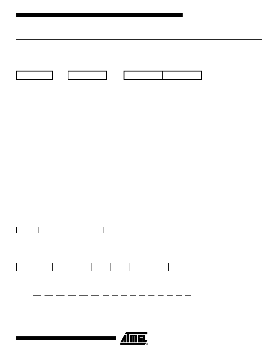
71
AVR Instruction Set
0856D–AVR–08/02
FMUL – Fractional Multiply Unsigned
Description:
This instruction performs 8-bit
×
8-bit
→
16-bit unsigned multiplication and shifts the result one bit left
.
Let (N.Q) denote a fractional number with N binary digits left of the radix point, and Q binary digits right of the radix point. A
multiplication between two numbers in the formats (N1.Q1) and (N2.Q2) results in the format ((N1+N2).(Q1+Q2)). For sig-
nal processing applications, the format (1.7) is widely used for the inputs, resulting in a (2.14) format for the product. A left
shift is required for the high byte of the product to be in the same format as the inputs. The FMUL instruction incorporates
the shift operation in the same number of cycles as MUL.
The (1.7) format is most commonly used with signed numbers, while FMUL performs an unsigned multiplication. This
instruction is therefore most useful for calculating one of the partial products when performing a signed multiplication with
16-bit inputs in the (1.15) format, yielding a result in the (1.31) format. Note: the result of the FMUL operation may suffer
from a 2’s complement overflow if interpreted as a number in the (1.15) format. The MSB of the multiplication before shift-
ing must be taken into account, and is found in the carry bit. See the following example.
The multiplicand Rd and the multiplier Rr are two registers containing unsigned fractional numbers where the implicit radix
point lies between bit 6 and bit 7. The 16-bit unsigned fractional product with the implicit radix point between bit 14 and bit
15 is placed in R1 (high byte) and R0 (low byte).
This instruction is not available in all devices. Refer to the device specific instruction set summary.
Operation:
(i)
R1:R0
←
Rd
×
Rr
(unsigned (1.15)
←
unsigned (1.7)
×
unsigned (1.7))
Syntax:
Operands:
Program Counter:
(i)
FMUL Rd,Rr
16
≤
d
≤
23, 16
≤
r
≤
23
PC
←
PC + 1
16-bit Opcode:
Status Register (SREG) and Boolean Formula:
C:
R16
Set if bit 15 of the result before left shift is set; cleared otherwise.
Z:
R15
•
R14
•
R13
•
R12
•
R11
•
R10
•
R9
•
R8
•
R7
•
R6
•
R5
•
R4
•
R3
•
R2
•
R1
•
R0
Set if the result is $0000; cleared otherwise.
R (Result) equals R1,R0 after the operation.
Rd
Rr
R1
R0
Multiplicand
×
Multiplier
Æ
Product High
Product Low
8
8
16
0000
0011
0ddd
1rrr
I
T
H
S
V
N
Z
C
–
–
–
–
–
–
⇔
⇔

72
AVR Instruction Set
0856D–AVR–08/02
Example:
;******************************************************************************
;* DESCRIPTION
;*Signed fractional multiply of two 16-bit numbers with 32-bit result.
;* USAGE
;*r19:r18:r17:r16 = ( r23:r22 * r21:r20 ) << 1
;******************************************************************************
fmuls16x16_32:
clrr2
fmulsr23, r21;((signed)ah * (signed)bh) << 1
movwr19:r18, r1:r0
fmulr22, r20;(al * bl) << 1
adcr18, r2
movwr17:r16, r1:r0
fmulsur23, r20;((signed)ah * bl) << 1
sbcr19, r2
addr17, r0
adcr18, r1
adcr19, r2
fmulsur21, r22;((signed)bh * al) << 1
sbcr19, r2
addr17, r0
adcr18, r1
adcr19, r2
Words: 1 (2 bytes)
Cycles: 2
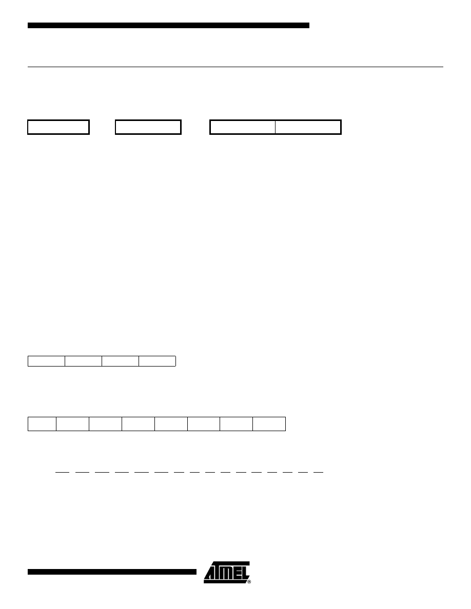
73
AVR Instruction Set
0856D–AVR–08/02
FMULS – Fractional Multiply Signed
Description:
This instruction performs 8-bit
×
8-bit
→
16-bit signed multiplication and shifts the result one bit left
.
Let (N.Q) denote a fractional number with N binary digits left of the radix point, and Q binary digits right of the radix point. A
multiplication between two numbers in the formats (N1.Q1) and (N2.Q2) results in the format ((N1+N2).(Q1+Q2)). For sig-
nal processing applications, the format (1.7) is widely used for the inputs, resulting in a (2.14) format for the product. A left
shift is required for the high byte of the product to be in the same format as the inputs. The FMULS instruction incorporates
the shift operation in the same number of cycles as MULS.
The multiplicand Rd and the multiplier Rr are two registers containing signed fractional numbers where the implicit radix
point lies between bit 6 and bit 7. The 16-bit signed fractional product with the implicit radix point between bit 14 and bit 15
is placed in R1 (high byte) and R0 (low byte).
Note that when multiplying 0x80 (-1) with 0x80 (-1), the result of the shift operation is 0x8000 (-1). The shift operation thus
gives a two’s complement overflow. This must be checked and handled by software.
This instruction is not available in all devices. Refer to the device specific instruction set summary.
Operation:
(i)
R1:R0
←
Rd
×
Rr
(signed (1.15)
←
signed (1.7)
×
signed (1.7))
Syntax:
Operands:
Program Counter:
(i)
FMULS Rd,Rr
16
≤
d
≤
23, 16
≤
r
≤
23
PC
←
PC + 1
16-bit Opcode:
Status Register (SREG) and Boolean Formula:
C:
R16
Set if bit 15 of the result before left shift is set; cleared otherwise.
Z:
R15
•
R14
•
R13
•
R12
•
R11
•
R10
•
R9
•
R8
•
R7
•
R6
•
R5
•
R4
•
R3
•
R2
•
R1
•
R0
Set if the result is $0000; cleared otherwise.
R (Result) equals R1,R0 after the operation.
Example:
fmuls r23,r22
; Multiply signed r23 and r22 in (1.7) format, result in (1.15) format
movw
r23:r22,r1:r0
; Copy result back in r23:r22
Rd
Rr
R1
R0
Multiplicand
×
Multiplier
→
Product High
Product Low
8
8
16
0000
0011
1ddd
0rrr
I
T
H
S
V
N
Z
C
–
–
–
–
–
–
⇔
⇔

74
AVR Instruction Set
0856D–AVR–08/02
Words: 1 (2 bytes)
Cycles: 2

75
AVR Instruction Set
0856D–AVR–08/02
FMULSU – Fractional Multiply Signed with Unsigned
Description:
This instruction performs 8-bit
×
8-bit
→
16-bit signed multiplication and shifts the result one bit left
.
Let (N.Q) denote a fractional number with N binary digits left of the radix point, and Q binary digits right of the radix point. A
multiplication between two numbers in the formats (N1.Q1) and (N2.Q2) results in the format ((N1+N2).(Q1+Q2)). For sig-
nal processing applications, the format (1.7) is widely used for the inputs, resulting in a (2.14) format for the product. A left
shift is required for the high byte of the product to be in the same format as the inputs. The FMULSU instruction incorpo-
rates the shift operation in the same number of cycles as MULSU.
The (1.7) format is most commonly used with signed numbers, while FMULSU performs a multiplication with one unsigned
and one signed input. This instruction is therefore most useful for calculating two of the partial products when performing a
signed multiplication with 16-bit inputs in the (1.15) format, yielding a result in the (1.31) format. Note: the result of the
FMULSU operation may suffer from a 2's complement overflow if interpreted as a number in the (1.15) format. The MSB of
the multiplication before shifting must be taken into account, and is found in the carry bit. See the following example.
The multiplicand Rd and the multiplier Rr are two registers containing fractional numbers where the implicit radix point lies
between bit 6 and bit 7. The multiplicand Rd is a signed fractional number, and the multiplier Rr is an unsigned fractional
number. The 16-bit signed fractional product with the implicit radix point between bit 14 and bit 15 is placed in R1 (high
byte) and R0 (low byte).
This instruction is not available in all devices. Refer to the device specific instruction set summary.
Operation:
(i)
R1:R0
←
Rd
×
Rr
(signed (1.15)
←
signed (1.7)
×
unsigned (1.7))
Syntax:
Operands:
Program Counter:
(i)
FMULSU Rd,Rr
16
≤
d
≤
23, 16
≤
r
≤
23
PC
←
PC + 1
16-bit Opcode:
Status Register (SREG) and Boolean Formula:
C:
R16
Set if bit 15 of the result before left shift is set; cleared otherwise.
Z:
R15
•
R14
•
R13
•
R12
•
R11
•
R10
•
R9
•
R8
•
R7
•
R6
•
R5
•
R4
•
R3
•
R2
•
R1
•
R0
Set if the result is $0000; cleared otherwise.
R (Result) equals R1,R0 after the operation.
Rd
Rr
R1
R0
Multiplicand
×
Multiplier
→
Product High
Product Low
8
8
16
0000
0011
1ddd
1rrr
I
T
H
S
V
N
Z
C
–
–
–
–
–
–
⇔
⇔

76
AVR Instruction Set
0856D–AVR–08/02
Example:
;******************************************************************************
;* DESCRIPTION
;*Signed fractional multiply of two 16-bit numbers with 32-bit result.
;* USAGE
;*r19:r18:r17:r16 = ( r23:r22 * r21:r20 ) << 1
;******************************************************************************
fmuls16x16_32:
clrr2
fmulsr23, r21;((signed)ah * (signed)bh) << 1
movwr19:r18, r1:r0
fmulr22, r20;(al * bl) << 1
adcr18, r2
movwr17:r16, r1:r0
fmulsur23, r20;((signed)ah * bl) << 1
sbcr19, r2
addr17, r0
adcr18, r1
adcr19, r2
fmulsur21, r22;((signed)bh * al) << 1
sbcr19, r2
addr17, r0
adcr18, r1
adcr19, r2
Words: 1 (2 bytes)
Cycles: 2
77
AVR Instruction Set
0856D–AVR–08/02
ICALL – Indirect Call to Subroutine
Description:
Indirect call of a subroutine pointed to by the Z (16 bits) Pointer Register in the Register File. The Z-pointer Register is 16
bits wide and allows call to a subroutine within the lowest 64K words (128K bytes) section in the Program memory space.
The Stack Pointer uses a post-decrement scheme during ICALL.
This instruction is not available in all devices. Refer to the device specific instruction set summary.
Operation:
(i)
PC(15:0)
←
Z(15:0) Devices with 16 bits PC, 128K bytes Program memory maximum.
(ii)
PC(15:0)
←
Z(15:0) Devices with 22 bits PC, 8M bytes Program memory maximum.
PC(21:16)
←
0
Syntax:
Operands:
Program Counter:
Stack:
(i)
ICALL
None
See Operation
STACK
←
PC + 1
SP
←
SP - 2 (2 bytes, 16 bits)
(ii)
ICALL
None
See Operation
STACK
←
PC + 1
SP
←
SP - 3 (3 bytes, 22 bits)
16-bit Opcode:
Status Register (SREG) and Boolean Formula:
Example:
mov
r30,r0
; Set offset to call table
icall
; Call routine pointed to by r31:r30
Words: 1 (2 bytes)
Cycles: 3 devices with 16 bit PC
4 devices with 22 bit PC
1001
0101
0000
1001
I
T
H
S
V
N
Z
C
–
–
–
–
–
–
–
–

78
AVR Instruction Set
0856D–AVR–08/02
IJMP – Indirect Jump
Description:
Indirect jump to the address pointed to by the Z (16 bits) Pointer Register in the Register File. The Z-pointer Register is 16
bits wide and allows jump within the lowest 64K words (128K bytes) section of Program memory.
This instruction is not available in all devices. Refer to the device specific instruction set summary.
Operation:
(i)
PC
←
Z(15:0)
Devices with 16 bits PC, 128K bytes Program memory maximum.
(ii)
PC(15:0)
←
Z(15:0) Devices with 22 bits PC, 8M bytes Program memory maximum.
PC(21:16)
←
0
Syntax:
Operands:
Program Counter:
Stack:
(i),(ii)
IJMP
None
See Operation
Not Affected
16-bit Opcode:
Status Register (SREG) and Boolean Formula:
Example:
mov
r30,r0
; Set offset to jump table
ijmp
; Jump to routine pointed to by r31:r30
Words: 1 (2 bytes)
Cycles: 2
1001
0100
0000
1001
I
T
H
S
V
N
Z
C
–
–
–
–
–
–
–
–

79
AVR Instruction Set
0856D–AVR–08/02
IN - Load an I/O Location to Register
Description:
Loads data from the I/O Space (Ports, Timers, Configuration Registers etc.) into register Rd in the Register File.
Operation:
(i)
Rd
←
I/O(A)
Syntax:
Operands:
Program Counter:
(i)
IN Rd,A
0
≤
d
≤
31, 0
≤
A
≤
63
PC
←
PC + 1
16-bit Opcode:
Status Register (SREG) and Boolean Formula:
Example:
in
r25,$16
; Read Port B
cpi
r25,4
; Compare read value to constant
breq
exit
; Branch if r25=4
...
exit:
nop
; Branch destination (do nothing)
Words: 1 (2 bytes)
Cycles: 1
1011
0AAd
dddd
AAAA
I
T
H
S
V
N
Z
C
–
–
–
–
–
–
–
–

80
AVR Instruction Set
0856D–AVR–08/02
INC – Increment
Description:
Adds one -1- to the contents of register Rd and places the result in the destination register Rd.
The C Flag in SREG is not affected by the operation, thus allowing the INC instruction to be used on a loop counter in mul-
tiple-precision computations.
When operating on unsigned numbers, only BREQ and BRNE branches can be expected to perform consistently. When
operating on two’s complement values, all signed branches are available.
Operation:
(i)
Rd
←
Rd + 1
Syntax:
Operands:
Program Counter:
(i)
INC Rd
0
≤
d
≤
31
PC
←
PC + 1
16-bit Opcode:
Status Register and Boolean Formula:
S:
N
⊕
V
For signed tests.
V:
R7
•
R6
•
R5
•
R4
•
R3
•
R2
•
R1
•
R0
Set if two’s complement overflow resulted from the operation; cleared otherwise. Two’s complement overflow occurs
if and only if Rd was $7F before the operation.
N:
R7
Set if MSB of the result is set; cleared otherwise.
Z:
R7
•
R6
•
R5
•
R4
•
R3
•
R2
•
R1
•
R0
Set if the result is $00; Cleared otherwise.
R (Result) equals Rd after the operation.
Example:
clr
r22
; clear r22
loop:
inc
r22
; increment r22
...
cpi
r22,$4F
; Compare r22 to $4f
brne
loop
; Branch if not equal
nop
; Continue (do nothing)
1001
010d
dddd
0011
I
T
H
S
V
N
Z
C
–
–
–
⇔
⇔
⇔
⇔
–

81
AVR Instruction Set
0856D–AVR–08/02
Words: 1 (2 bytes)
Cycles: 1
82
AVR Instruction Set
0856D–AVR–08/02
JMP – Jump
Description:
Jump to an address within the entire 4M (words) Program memory. See also RJMP.
This instruction is not available in all devices. Refer to the device specific instruction set summary.
Operation:
(i)
PC
←
k
Syntax:
Operands:
Program Counter:
Stack:
(i)
JMP k
0
≤
k
<
4M
PC
←
k
Unchanged
32-bit Opcode:
Status Register (SREG) and Boolean Formula:
Example:
mov
r1,r0
; Copy r0 to r1
jmp
farplc
; Unconditional jump
...
farplc: nop
; Jump destination (do nothing)
Words: 2 (4 bytes)
Cycles: 3
1001
010k
kkkk
110k
kkkk
kkkk
kkkk
kkkk
I
T
H
S
V
N
Z
C
–
–
–
–
–
–
–
–
83
AVR Instruction Set
0856D–AVR–08/02
LD – Load Indirect from Data Space to Register using Index X
Description:
Loads one byte indirect from the data space to a register. For parts with SRAM, the data space consists of the Register
File, I/O memory and internal SRAM (and external SRAM if applicable). For parts without SRAM, the data space consists of
the Register File only. The EEPROM has a separate address space.
The data location is pointed to by the X (16 bits) Pointer Register in the Register File. Memory access is limited to the cur-
rent data segment of 64K bytes. To access another data segment in devices with more than 64K bytes data space, the
RAMPX in register in the I/O area has to be changed.
The X-pointer Register can either be left unchanged by the operation, or it can be post-incremented or pre-decremented.
These features are especially suited for accessing arrays, tables, and Stack Pointer usage of the X-pointer Register. Note
that only the low byte of the X-pointer is updated in devices with no more than 256 bytes data space. For such devices, the
high byte of the pointer is not used by this instruction and can be used for other purposes. The RAMPX Register in the I/O
area is updated in parts with more than 64K bytes data space or more than 64K bytes Program memory, and the incre-
ment/decrement is added to the entire 24-bit address on such devices.
Not all variants of this instruction is available in all devices. Refer to the device specific instruction set summary.
The result of these combinations is undefined:
LD r26, X+
LD r27, X+
LD r26, -X
LD r27, -X
Using the X-pointer:
Operation:
Comment:
(i)
Rd
←
(X)
X: Unchanged
(ii)
Rd
←
(X)
X
←
X + 1
X: Post incremented
(iii)
X
←
X - 1
Rd
←
(X)
X: Pre decremented
Syntax:
Operands:
Program Counter:
(i)
LD Rd, X
0
≤
d
≤
31
PC
←
PC + 1
(ii)
LD Rd, X+
0
≤
d
≤
31
PC
←
PC + 1
(iii)
LD Rd, -X
0
≤
d
≤
31
PC
←
PC + 1
16-bit Opcode:
Status Register (SREG) and Boolean Formula:
Example:
clr
r27
; Clear X high byte
ldi
r26,$60
; Set X low byte to $60
(i)
1001
000d
dddd
1100
(ii)
1001
000d
dddd
1101
(iii)
1001
000d
dddd
1110
I
T
H
S
V
N
Z
C
–
–
–
–
–
–
–
–

84
AVR Instruction Set
0856D–AVR–08/02
ld
r0,X+
; Load r0 with data space loc. $60(X post inc)
ld
r1,X
; Load r1 with data space loc. $61
ldi
r26,$63
; Set X low byte to $63
ld
r2,X
; Load r2 with data space loc. $63
ld
r3,–X
; Load r3 with data space loc. $62(X pre dec)
Words: 1 (2 bytes)
Cycles: 2

85
AVR Instruction Set
0856D–AVR–08/02
LD (LDD) – Load Indirect from Data Space to Register using Index Y
Description:
Loads one byte indirect with or without displacement from the data space to a register. For parts with SRAM, the data
space consists of the Register File, I/O memory and internal SRAM (and external SRAM if applicable). For parts without
SRAM, the data space consists of the Register File only. The EEPROM has a separate address space.
The data location is pointed to by the Y (16 bits) Pointer Register in the Register File. Memory access is limited to the cur-
rent data segment of 64K bytes. To access another data segment in devices with more than 64K bytes data space, the
RAMPY in register in the I/O area has to be changed.
The Y-pointer Register can either be left unchanged by the operation, or it can be post-incremented or pre-decremented.
These features are especially suited for accessing arrays, tables, and Stack Pointer usage of the Y-pointer Register. Note
that only the low byte of the Y-pointer is updated in devices with no more than 256 bytes data space. For such devices, the
high byte of the pointer is not used by this instruction and can be used for other purposes. The RAMPY Register in the I/O
area is updated in parts with more than 64K bytes data space or more than 64K bytes Program memory, and the incre-
ment/decrement/displacement is added to the entire 24-bit address on such devices.
Not all variants of this instruction is available in all devices. Refer to the device specific instruction set summary.
The result of these combinations is undefined:
LD r28, Y+
LD r29, Y+
LD r28, -Y
LD r29, -Y
Using the Y-pointer:
Operation:
Comment:
(i)
Rd
←
(Y)
Y: Unchanged
(ii)
Rd
←
(Y)
Y
←
Y + 1
Y: Post incremented
(iii)
Y
←
Y - 1
Rd
←
(Y)
Y: Pre decremented
(iiii)
Rd
←
(Y+q)
Y: Unchanged, q: Displacement
Syntax:
Operands:
Program Counter:
(i)
LD Rd, Y
0
≤
d
≤
31
PC
←
PC + 1
(ii)
LD Rd, Y+
0
≤
d
≤
31
PC
←
PC + 1
(iii)
LD Rd, -Y
0
≤
d
≤
31
PC
←
PC + 1
(iiii)
LDD Rd, Y+q
0
≤
d
≤
31, 0
≤
q
≤
63
PC
←
PC + 1

86
AVR Instruction Set
0856D–AVR–08/02
16-bit Opcode:
Status Register (SREG) and Boolean Formula:
Example:
clr
r29
; Clear Y high byte
ldi
r28,$60
; Set Y low byte to $60
ld
r0,Y+
; Load r0 with data space loc. $60(Y post inc)
ld
r1,Y
; Load r1 with data space loc. $61
ldi
r28,$63
; Set Y low byte to $63
ld
r2,Y
; Load r2 with data space loc. $63
ld
r3,-Y
; Load r3 with data space loc. $62(Y pre dec)
ldd
r4,Y+2
; Load r4 with data space loc. $64
Words: 1 (2 bytes)
Cycles: 2
(i)
1000
000d
dddd
1000
(ii)
1001
000d
dddd
1001
(iii)
1001
000d
dddd
1010
(iiii)
10q0
qq0d
dddd
1qqq
I
T
H
S
V
N
Z
C
–
–
–
–
–
–
–
–

87
AVR Instruction Set
0856D–AVR–08/02
LD (LDD) – Load Indirect From Data Space to Register using Index Z
Description:
Loads one byte indirect with or without displacement from the data space to a register. For parts with SRAM, the data
space consists of the Register File, I/O memory and internal SRAM (and external SRAM if applicable). For parts without
SRAM, the data space consists of the Register File only. The EEPROM has a separate address space.
The data location is pointed to by the Z (16 bits) Pointer Register in the Register File. Memory access is limited to the cur-
rent data segment of 64K bytes. To access another data segment in devices with more than 64K bytes data space, the
RAMPZ in register in the I/O area has to be changed.
The Z-pointer Register can either be left unchanged by the operation, or it can be post-incremented or pre-decremented.
These features are especially suited for Stack Pointer usage of the Z-pointer Register, however because the Z-pointer
Register can be used for indirect subroutine calls, indirect jumps and table lookup, it is often more convenient to use the X
or Y-pointer as a dedicated Stack Pointer. Note that only the low byte of the Z-pointer is updated in devices with no more
than 256 bytes data space. For such devices, the high byte of the pointer is not used by this instruction and can be used for
other purposes. The RAMPZ Register in the I/O area is updated in parts with more than 64K bytes data space or more than
64K bytes Program memory, and the increment/decrement/displacement is added to the entire 24-bit address on such
devices.
Not all variants of this instruction is available in all devices. Refer to the device specific instruction set summary.
For using the Z-pointer for table lookup in Program memory see the LPM and ELPM instructions.
The result of these combinations is undefined:
LD r30, Z+
LD r31, Z+
LD r30, -Z
LD r31, -Z
Using the Z-pointer:
Operation:
Comment:
(i)
Rd
←
(Z)
Z: Unchanged
(ii)
Rd
←
(Z)
Z
←
Z + 1
Z: Post increment
(iii)
Z
←
Z -1
Rd
←
(Z)
Z: Pre decrement
(iiii)
Rd
←
(Z+q)
Z: Unchanged, q: Displacement
Syntax:
Operands:
Program Counter:
(i)
LD Rd, Z
0
≤
d
≤
31
PC
←
PC + 1
(ii)
LD Rd, Z+
0
≤
d
≤
31
PC
←
PC + 1
(iii)
LD Rd, -Z
0
≤
d
≤
31
PC
←
PC + 1
(iiii)
LDD Rd, Z+q
0
≤
d
≤
31, 0
≤
q
≤
63
PC
←
PC + 1
88
AVR Instruction Set
0856D–AVR–08/02
16-bit Opcode:
Status Register (SREG) and Boolean Formula:
Example:
clr
r31
; Clear Z high byte
ldi
r30,$60
; Set Z low byte to $60
ld
r0,Z+
; Load r0 with data space loc. $60(Z post inc)
ld
r1,Z
; Load r1 with data space loc. $61
ldi
r30,$63
; Set Z low byte to $63
ld
r2,Z
; Load r2 with data space loc. $63
ld
r3,-Z
; Load r3 with data space loc. $62(Z pre dec)
ldd
r4,Z+2
; Load r4 with data space loc. $64
Words: 1 (2 bytes)
Cycles: 2
(i)
1000
000d
dddd
0000
(ii)
1001
000d
dddd
0001
(iii)
1001
000d
dddd
0010
(iiii)
10q0
qq0d
dddd
0qqq
I
T
H
S
V
N
Z
C
–
–
–
–
–
–
–
–

89
AVR Instruction Set
0856D–AVR–08/02
LDI – Load Immediate
Description:
Loads an 8 bit constant directly to register 16 to 31.
Operation:
(i)
Rd
←
K
Syntax:
Operands:
Program Counter:
(i)
LDI Rd,K
16
≤
d
≤
31, 0
≤
K
≤
255
PC
←
PC + 1
16-bit Opcode:
Status Register (SREG) and Boolean Formula:
Example:
clr
r31
; Clear Z high byte
ldi
r30,$F0
; Set Z low byte to $F0
lpm
; Load constant from Program
; memory pointed to by Z
Words: 1 (2 bytes)
Cycles: 1
1110
KKKK
dddd
KKKK
I
T
H
S
V
N
Z
C
–
–
–
–
–
–
–
–

90
AVR Instruction Set
0856D–AVR–08/02
LDS – Load Direct from Data Space
Description:
Loads one byte from the data space to a register. For parts with SRAM, the data space consists of the Register File, I/O
memory and internal SRAM (and external SRAM if applicable). For parts without SRAM, the data space consists of the reg-
ister file only. The EEPROM has a separate address space.
A 16-bit address must be supplied. Memory access is limited to the current data segment of 64K bytes. The LDS instruction
uses the RAMPD Register to access memory above 64K bytes. To access another data segment in devices with more than
64K bytes data space, the RAMPD in register in the I/O area has to be changed.
This instruction is not available in all devices. Refer to the device specific instruction set summary.
Operation:
(i)
Rd
←
(k)
Syntax:
Operands:
Program Counter:
(i)
LDS Rd,k
0
≤
d
≤
31, 0
≤
k
≤
65535
PC
←
PC + 2
32-bit Opcode:
Status Register (SREG) and Boolean Formula:
Example:
lds
r2,$FF00
; Load r2 with the contents of data space location $FF00
add
r2,r1
; add r1 to r2
sts
$FF00,r2
; Write back
Words: 2 (4 bytes)
Cycles: 2
1001
000d
dddd
0000
kkkk
kkkk
kkkk
kkkk
I
T
H
S
V
N
Z
C
–
–
–
–
–
–
–
–
91
AVR Instruction Set
0856D–AVR–08/02
LPM – Load Program Memory
Description:
Loads one byte pointed to by the Z-register into the destination register Rd. This instruction features a 100% space effec-
tive constant initialization or constant data fetch. The Program memory is organized in 16-bit words while the Z-pointer is a
byte address. Thus, the least significant bit of the Z-pointer selects either low byte (Z
LSB
= 0) or high byte (Z
LSB
= 1). This
instruction can address the first 64K bytes (32K words) of Program memory. The Z-pointer Register can either be left
unchanged by the operation, or it can be incremented. The incrementation does not apply to the RAMPZ Register.
Devices with Self-Programming capability can use the LPM instruction to read the Fuse and Lock bit values. Refer to the
device documentation for a detailed description.
Not all variants of the LPM instruction are available in all devices. Refer to the device specific instruction set summary. The
LPM instruction is not implemented at all in the AT90S1200 device.
The result of these combinations is undefined:
LPM r30, Z+
LPM r31, Z+
Operation:
Comment:
(i)
R0
←
(Z)
Z: Unchanged, R0 implied destination register
(ii)
Rd
←
(Z)
Z: Unchanged
(iii)
Rd
←
(Z)
Z
←
Z + 1
Z: Post incremented
Syntax:
Operands:
Program Counter:
(i)
LPM
None, R0 implied
PC
←
PC + 1
(ii)
LPM Rd, Z
0
≤
d
≤
31
PC
←
PC + 1
(iii)
LPM Rd, Z+
0
≤
d
≤
31
PC
←
PC + 1
16-bit Opcode:
Status Register (SREG) and Boolean Formula:
Example:
ldi
ZH, high(Table_1<<1); Initialize Z-pointer
ldi
ZL, low(Table_1<<1)
lpm
r16, Z
; Load constant from Program
; Memory pointed to by Z (r31:r30)
...
Table_1:
.dw 0x5876
; 0x76 is addresses when Z
LSB
= 0
; 0x58 is addresses when Z
LSB
= 1
...
(i)
1001
0101
1100
1000
(ii)
1001
000d
dddd
0100
(iii)
1001
000d
dddd
0101
I
T
H
S
V
N
Z
C
–
–
–
–
–
–
–
–

92
AVR Instruction Set
0856D–AVR–08/02
Words: 1 (2 bytes)
Cycles: 3
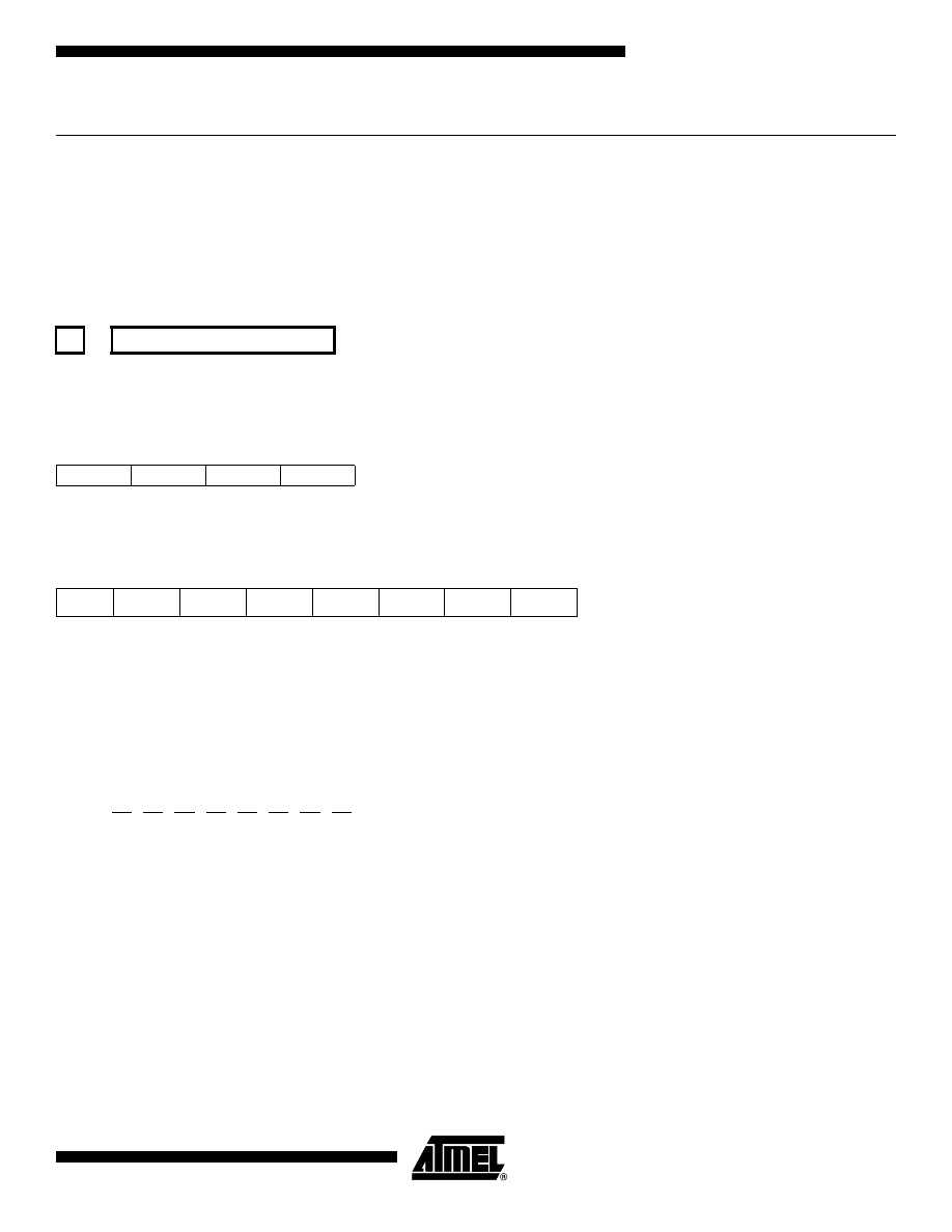
93
AVR Instruction Set
0856D–AVR–08/02
LSL – Logical Shift Left
Description:
Shifts all bits in Rd one place to the left. Bit 0 is cleared. Bit 7 is loaded into the C Flag of the SREG. This operation effec-
tively multiplies signed and unsigned values by two.
Operation:
(i)
Syntax:
Operands:
Program Counter:
(i)
LSL Rd
0
≤
d
≤
31
PC
←
PC + 1
16-bit Opcode: (see ADD Rd,Rd)
Status Register (SREG) and Boolean Formula:
H:
Rd3
S:
N
⊕
V, For signed tests.
V:
N
⊕
C (For N and C after the shift)
N:
R7
Set if MSB of the result is set; cleared otherwise.
Z:
R7
•
R6
•
R5
•
R4
•
R3
•
R2
•
R1
•
R0
Set if the result is $00; cleared otherwise.
C:
Rd7
Set if, before the shift, the MSB of Rd was set; cleared otherwise.
R (Result) equals Rd after the operation.
Example:
add
r0,r4
; Add r4 to r0
lsl
r0
; Multiply r0 by 2
Words: 1 (2 bytes)
Cycles: 1
←
C
←
b7 - - - - - - - - - - - - - - - - - - b0
←
0
0000
11dd
dddd
dddd
I
T
H
S
V
N
Z
C
–
–
⇔
⇔
⇔
⇔
⇔
⇔

94
AVR Instruction Set
0856D–AVR–08/02
LSR – Logical Shift Right
Description:
Shifts all bits in Rd one place to the right. Bit 7 is cleared. Bit 0 is loaded into the C Flag of the SREG. This operation effec-
tively divides an unsigned value by two. The C Flag can be used to round the result.
Operation:
Syntax:
Operands:
Program Counter:
(i)
LSR Rd
0
≤
d
≤
31
PC
←
PC + 1
16-bit Opcode:
Status Register (SREG) and Boolean Formula:
S:
N
⊕
V, For signed tests.
V:
N
⊕
C (For N and C after the shift)
N:
0
Z:
R7
•
R6
•
R5
•
R4
•
R3
•
R2
•
R1
•
R0
Set if the result is $00; cleared otherwise.
C:
Rd0
Set if, before the shift, the LSB of Rd was set; cleared otherwise.
R (Result) equals Rd after the operation.
Example:
add
r0,r4
; Add r4 to r0
lsr
r0
; Divide r0 by 2
Words: 1 (2 bytes)
Cycles: 1
→
0
→
b7 - - - - - - - - - - - - - - - - - - b0
→
C
1001
010d
dddd
0110
I
T
H
S
V
N
Z
C
–
–
–
⇔
⇔
0
⇔
⇔

95
AVR Instruction Set
0856D–AVR–08/02
MOV – Copy Register
Description:
This instruction makes a copy of one register into another. The source register Rr is left unchanged, while the destination
register Rd is loaded with a copy of Rr.
Operation:
(i)
Rd
←
Rr
Syntax:
Operands:
Program Counter:
(i)
MOV Rd,Rr
0
≤
d
≤
31, 0
≤
r
≤
31
PC
←
PC + 1
16-bit Opcode:
Status Register (SREG) and Boolean Formula:
Example:
mov
r16,r0
; Copy r0 to r16
call
check
; Call subroutine
...
check:
cpi
r16,$11
; Compare r16 to $11
...
ret
; Return from subroutine
Words: 1 (2 bytes)
Cycles: 1
0010
11rd
dddd
rrrr
I
T
H
S
V
N
Z
C
–
–
–
–
–
–
–
–

96
AVR Instruction Set
0856D–AVR–08/02
MOVW – Copy Register Word
Description:
This instruction makes a copy of one register pair into another register pair. The source register pair Rr+1:Rr is left
unchanged, while the destination register pair Rd+1:Rd is loaded with a copy of Rr + 1:Rr.
This instruction is not available in all devices. Refer to the device specific instruction set summary.
Operation:
(i)
Rd+1:Rd
←
Rr+1:Rr
Syntax:
Operands:
Program Counter:
(i)
MOVW Rd+1:Rd,Rr+1Rrd
∈
{0,2,...,30}, r
∈
{0,2,...,30}
PC
←
PC + 1
16-bit Opcode:
Status Register (SREG) and Boolean Formula:
Example:
movw
r17:16,r1:r0 ; Copy r1:r0 to r17:r16
call
check
; Call subroutine
...
check:
cpi
r16,$11
; Compare r16 to $11
...
cpi
r17,$32
; Compare r17 to $32
...
ret
; Return from subroutine
Words: 1 (2 bytes)
Cycles: 1
0000
0001
dddd
rrrr
I
T
H
S
V
N
Z
C
–
–
–
–
–
–
–
–
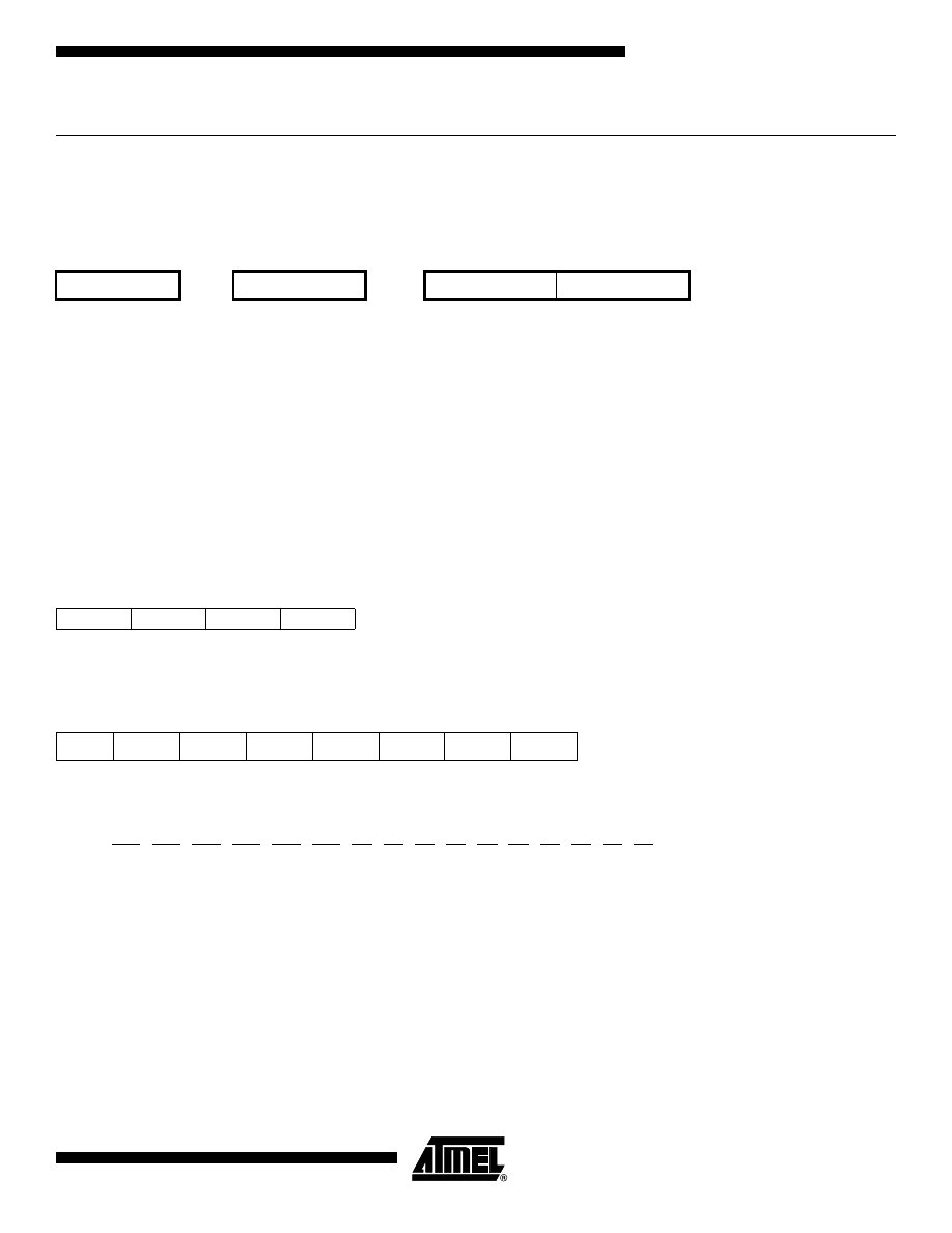
97
AVR Instruction Set
0856D–AVR–08/02
MUL – Multiply Unsigned
Description:
This instruction performs 8-bit
×
8-bit
→
16-bit unsigned multiplication.
The multiplicand Rd and the multiplier Rr are two registers containing unsigned numbers. The 16-bit unsigned product is
placed in R1 (high byte) and R0 (low byte). Note that if the multiplicand or the multiplier is selected from R0 or R1 the result
will overwrite those after multiplication.
This instruction is not available in all devices. Refer to the device specific instruction set summary.
Operation:
(i)
R1:R0
←
Rd
×
Rr
(unsigned
←
unsigned
×
unsigned)
Syntax:
Operands:
Program Counter:
(i)
MUL Rd,Rr
0
≤
d
≤
31, 0
≤
r
≤
31
PC
←
PC + 1
16-bit Opcode:
Status Register (SREG) and Boolean Formula:
C:
R15
Set if bit 15 of the result is set; cleared otherwise.
Z:
R15
•
R14
•
R13
•
R12
•
R11
•
R10
•
R9
•
R8
•
R7
•
R6
•
R5
•
R4
•
R3
•
R2
•
R1
•
R0
Set if the result is $0000; cleared otherwise.
R (Result) equals R1,R0 after the operation.
Example:
mul
r5,r4
; Multiply unsigned r5 and r4
movw
r4,r0
; Copy result back in r5:r4
Words: 1 (2 bytes)
Cycles: 2
Rd
Rr
R1
R0
Multiplicand
×
Multiplier
→
Product High
Product Low
8
8
16
1001
11rd
dddd
rrrr
I
T
H
S
V
N
Z
C
–
–
–
–
–
–
⇔
⇔
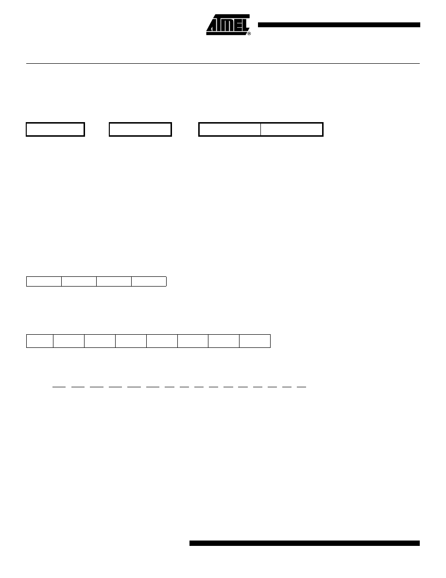
98
AVR Instruction Set
0856D–AVR–08/02
MULS – Multiply Signed
Description:
This instruction performs 8-bit
×
8-bit
→
16-bit signed multiplication.
The multiplicand Rd and the multiplier Rr are two registers containing signed numbers. The 16-bit signed product is placed
in R1 (high byte) and R0 (low byte).
This instruction is not available in all devices. Refer to the device specific instruction set summary.
Operation:
(i)
R1:R0
←
Rd
×
Rr
(signed
←
signed
×
signed)
Syntax:
Operands:
Program Counter:
(i)
MULS Rd,Rr
16
≤
d
≤
31, 16
≤
r
≤
31
PC
←
PC + 1
16-bit Opcode:
Status Register (SREG) and Boolean Formula:
C:
R15
Set if bit 15 of the result is set; cleared otherwise.
Z:
R15
•
R14
•
R13
•
R12
•
R11
•
R10
•
R9
•
R8
•
R7
•
R6
•
R5
•
R4
•
R3
•
R2
•
R1
•
R0
Set if the result is $0000; cleared otherwise.
R (Result) equals R1,R0 after the operation.
Example:
muls
r21,r20
; Multiply signed r21 and r20
movw
r20,r0
; Copy result back in r21:r20
Words: 1 (2 bytes)
Cycles: 2
Rd
Rr
R1
R0
Multiplicand
×
Multiplier
→
Product High
Product Low
8
8
16
0000
0010
dddd
rrrr
I
T
H
S
V
N
Z
C
–
–
–
–
–
–
⇔
⇔
99
AVR Instruction Set
0856D–AVR–08/02
MULSU – Multiply Signed with Unsigned
Description:
This instruction performs 8-bit
×
8-bit
→
16-bit multiplication of a signed and an unsigned number.
The multiplicand Rd and the multiplier Rr are two registers. The multiplicand Rd is a signed number, and the multiplier Rr is
unsigned. The 16-bit signed product is placed in R1 (high byte) and R0 (low byte).
This instruction is not available in all devices. Refer to the device specific instruction set summary.
Operation:
(i)
R1:R0
←
Rd
×
Rr
(signed
←
signed
×
unsigned)
Syntax:
Operands:
Program Counter:
(i)
MULSU Rd,Rr
16
≤
d
≤
23, 16
≤
r
≤
23
PC
←
PC + 1
16-bit Opcode:
Status Register (SREG) and Boolean Formula:
C:
R15
Set if bit 15 of the result is set; cleared otherwise.
Z:
R15
•
R14
•
R13
•
R12
•
R11
•
R10
•
R9
•
R8
•
R7
•
R6
•
R5
•
R4
•
R3
•
R2
•
R1
•
R0
Set if the result is $0000; cleared otherwise.
R (Result) equals R1,R0 after the operation.
Example:
;******************************************************************************
;* DESCRIPTION
;*Signed multiply of two 16-bit numbers with 32-bit result.
;* USAGE
;*r19:r18:r17:r16 = r23:r22 * r21:r20
;******************************************************************************
muls16x16_32:
clrr2
mulsr23, r21; (signed)ah * (signed)bh
Rd
Rr
R1
R0
Multiplicand
×
Multiplier
→
Product High
Product Low
8
8
16
0000
0011
0ddd
0rrr
I
T
H
S
V
N
Z
C
–
–
–
–
–
–
⇔
⇔

100
AVR Instruction Set
0856D–AVR–08/02
movwr19:r18, r1:r0
mulr22, r20; al * bl
movwr17:r16, r1:r0
mulsur23, r20; (signed)ah * bl
sbcr19, r2
addr17, r0
adcr18, r1
adcr19, r2
mulsur21, r22; (signed)bh * al
sbcr19, r2
addr17, r0
adcr18, r1
adcr19, r2
ret
Words: 1 (2 bytes)
Cycles: 2

101
AVR Instruction Set
0856D–AVR–08/02
NEG – Two’s Complement
Description:
Replaces the contents of register Rd with its two’s complement; the value $80 is left unchanged.
Operation:
(i)
Rd
←
$00 - Rd
Syntax:
Operands:
Program Counter:
(i)
NEG Rd
0
≤
d
≤
31
PC
←
PC + 1
16-bit Opcode:
Status Register (SREG) and Boolean Formula:
H:
R3 + Rd3
Set if there was a borrow from bit 3; cleared otherwise
S:
N
⊕
V
For signed tests.
V:
R7
•
R6
•
R5
•
R4
•
R3
•
R2
•
R1
•
R0
Set if there is a two’s complement overflow from the implied subtraction from zero; cleared otherwise. A two’s com-
plement overflow will occur if and only if the contents of the Register after operation (Result) is $80.
N:
R7
Set if MSB of the result is set; cleared otherwise.
Z:
R7
•
R6
•
R5
•
R4
•
R3
•
R2
•
R1
•
R0
Set if the result is $00; Cleared otherwise.
C:
R7 + R6 + R5 + R4 + R3 + R2 + R1 + R0
Set if there is a borrow in the implied subtraction from zero; cleared otherwise. The C Flag will be set in all cases
except when the contents of Register after operation is $00.
R (Result) equals Rd after the operation.
Example:
sub
r11,r0
; Subtract r0 from r11
brpl
positive
; Branch if result positive
neg
r11
; Take two’s complement of r11
positive:
nop
; Branch destination (do nothing)
Words: 1 (2 bytes)
Cycles: 1
1001
010d
dddd
0001
I
T
H
S
V
N
Z
C
–
–
⇔
⇔
⇔
⇔
⇔
⇔

102
AVR Instruction Set
0856D–AVR–08/02
NOP – No Operation
Description:
This instruction performs a single cycle No Operation.
Operation:
(i)
No
Syntax:
Operands:
Program Counter:
(i)
NOP
None
PC
←
PC + 1
16-bit Opcode:
Status Register (SREG) and Boolean Formula:
Example:
clr
r16
; Clear r16
ser
r17
; Set r17
out
$18,r16
; Write zeros to Port B
nop
; Wait (do nothing)
out
$18,r17
; Write ones to Port B
Words: 1 (2 bytes)
Cycles: 1
0000
0000
0000
0000
I
T
H
S
V
N
Z
C
–
–
–
–
–
–
–
–

103
AVR Instruction Set
0856D–AVR–08/02
OR – Logical OR
Description:
Performs the logical OR between the contents of register Rd and register Rr and places the result in the destination register
Rd.
Operation:
(i)
Rd
←
Rd v Rr
Syntax:
Operands:
Program Counter:
(i)
OR Rd,Rr
0
≤
d
≤
31, 0
≤
r
≤
31
PC
←
PC + 1
16-bit Opcode:
Status Register (SREG) and Boolean Formula:
S:
N
⊕
V, For signed tests.
V:
0
Cleared
N:
R7
Set if MSB of the result is set; cleared otherwise.
Z:
R7
•
R6
•
R5
•
R4
•
R3
•
R2
•
R1
•
R0
Set if the result is $00; cleared otherwise.
R (Result) equals Rd after the operation.
Example:
or
r15,r16
; Do bitwise or between registers
bst
r15,6
; Store bit 6 of r15 in T Flag
brts
ok
; Branch if T Flag set
...
ok:
nop
; Branch destination (do nothing)
Words: 1 (2 bytes)
Cycles: 1
0010
10rd
dddd
rrrr
I
T
H
S
V
N
Z
C
–
–
–
⇔
0
⇔
⇔
–

104
AVR Instruction Set
0856D–AVR–08/02
ORI – Logical OR with Immediate
Description:
Performs the logical OR between the contents of register Rd and a constant and places the result in the destination register
Rd.
Operation:
(i)
Rd
←
Rd v K
Syntax:
Operands:
Program Counter:
(i)
ORI Rd,K
16
≤
d
≤
31, 0
≤
K
≤
255
PC
←
PC + 1
16-bit Opcode:
Status Register (SREG) and Boolean Formula:
S:
N
⊕
V, For signed tests.
V:
0
Cleared
N:
R7
Set if MSB of the result is set; cleared otherwise.
Z:
R7
•
R6
•
R5
•
R4
•
R3
•
R2
•
R1
•
R0
Set if the result is $00; cleared otherwise.
R (Result) equals Rd after the operation.
Example:
ori
r16,$F0
; Set high nibble of r16
ori
r17,1
; Set bit 0 of r17
Words: 1 (2 bytes)
Cycles: 1
0110
KKKK
dddd
KKKK
I
T
H
S
V
N
Z
C
–
–
–
⇔
0
⇔
⇔
–

105
AVR Instruction Set
0856D–AVR–08/02
OUT – Store Register to I/O Location
Description:
Stores data from register Rr in the Register File to I/O Space (Ports, Timers, Configuration Registers etc.).
Operation:
(i)
I/O(A)
←
Rr
Syntax:
Operands:
Program Counter:
(i)
OUT A,Rr
0
≤
r
≤
31, 0
≤
A
≤
63
PC
←
PC + 1
16-bit Opcode:
Status Register (SREG) and Boolean Formula:
Example:
clr
r16
; Clear r16
ser
r17
; Set r17
out
$18,r16
; Write zeros to Port B
nop
; Wait (do nothing)
out
$18,r17
; Write ones to Port B
Words: 1 (2 bytes)
Cycles: 1
1011
1AAr
rrrr
AAAA
I
T
H
S
V
N
Z
C
–
–
–
–
–
–
–
–

106
AVR Instruction Set
0856D–AVR–08/02
POP – Pop Register from Stack
Description:
This instruction loads register Rd with a byte from the STACK. The Stack Pointer is pre-incremented by 1 before the POP.
This instruction is not available in all devices. Refer to the device specific instruction set summary.
Operation:
(i)
Rd
←
STACK
Syntax:
Operands:
Program Counter:
Stack:
(i)
POP Rd
0
≤
d
≤
31
PC
←
PC + 1
SP
←
SP + 1
16-bit Opcode:
Status Register (SREG) and Boolean Formula:
Example:
call
routine
; Call subroutine
...
routine:
push
r14
; Save r14 on the Stack
push
r13
; Save r13 on the Stack
...
pop
r13
; Restore r13
pop
r14
; Restore r14
ret
; Return from subroutine
Words: 1 (2 bytes)
Cycles: 2
1001
000d
dddd
1111
I
T
H
S
V
N
Z
C
–
–
–
–
–
–
–
–

107
AVR Instruction Set
0856D–AVR–08/02
PUSH – Push Register on Stack
Description:
This instruction stores the contents of register Rr on the STACK. The Stack Pointer is post-decremented by 1 after the
PUSH.
This instruction is not available in all devices. Refer to the device specific instruction set summary.
Operation:
(i)
STACK
←
Rr
Syntax:
Operands:
Program Counter:
Stack:
(i)
PUSH Rr
0
≤
r
≤
31
PC
←
PC + 1
SP
←
SP - 1
16-bit Opcode:
Status Register (SREG) and Boolean Formula:
Example:
call
routine ; Call subroutine
...
routine:
push
r14
; Save r14 on the Stack
push
r13
; Save r13 on the Stack
...
pop
r13
; Restore r13
pop
r14
; Restore r14
ret
; Return from subroutine
Words: 1 (2 bytes)
Cycles: 2
1001
001d
dddd
1111
I
T
H
S
V
N
Z
C
–
–
–
–
–
–
–
–

108
AVR Instruction Set
0856D–AVR–08/02
RCALL – Relative Call to Subroutine
Description:
Relative call to an address within PC - 2K + 1 and PC + 2K (words). The return address (the instruction after the RCALL) is
stored onto the Stack. (See also CALL). In the assembler, labels are used instead of relative operands. For AVR microcon-
trollers with Program memory not exceeding 4K words (8K bytes) this instruction can address the entire memory from
every address location. The Stack Pointer uses a post-decrement scheme during RCALL.
Operation:
(i)
PC
←
PC + k + 1
Devices with 16 bits PC, 128K bytes Program memory maximum.
(ii)
PC
←
PC + k + 1
Devices with 22 bits PC, 8M bytes Program memory maximum.
Syntax:
Operands:
Program Counter:
Stack:
(i)
RCALL k
-2K
≤
k
<
2K
PC
←
PC + k + 1
STACK
←
PC + 1
SP
←
SP - 2 (2 bytes, 16 bits)
(ii)
RCALL k
-2K
≤
k
<
2K
PC
←
PC + k + 1
STACK
←
PC + 1
SP
←
SP - 3 (3 bytes, 22 bits)
16-bit Opcode:
Status Register (SREG) and Boolean Formula:
Example:
rcall
routine
; Call subroutine
...
routine:
push
r14
; Save r14 on the Stack
...
pop
r14
; Restore r14
ret
; Return from subroutine
Words: 1 (2 bytes)
Cycles: 3 devices with 16-bit PC
4 devices with 22-bit PC
1101
kkkk
kkkk
kkkk
I
T
H
S
V
N
Z
C
–
–
–
–
–
–
–
–

109
AVR Instruction Set
0856D–AVR–08/02
RET – Return from Subroutine
Description:
Returns from subroutine. The return address is loaded from the STACK. The Stack Pointer uses a pre-increment scheme
during RET.
Operation:
(i)
PC(15:0)
←
STACK Devices with 16 bits PC, 128K bytes Program memory maximum.
(ii)
PC(21:0)
←
STACKDevices with 22 bits PC, 8M bytes Program memory maximum.
Syntax:
Operands:
Program Counter:
Stack:
(i)
RET
None
See Operation
SP
←
SP + 2, (2bytes,16 bits)
(ii)
RET
None
See Operation
SP
←
SP + 3, (3bytes,22 bits)
16-bit Opcode:
Status Register (SREG) and Boolean Formula:
Example:
call
routine
; Call subroutine
...
routine:
push
r14
; Save r14 on the Stack
...
pop
r14
; Restore r14
ret
; Return from subroutine
Words:
1 (2 bytes)
Cycles: 4 devices with 16-bit PC
5 devices with 22-bit PC
1001
0101
0000
1000
I
T
H
S
V
N
Z
C
–
–
–
–
–
–
–
–

110
AVR Instruction Set
0856D–AVR–08/02
RETI – Return from Interrupt
Description:
Returns from interrupt. The return address is loaded from the STACK and the Global Interrupt Flag is set.
Note that the Status Register is not automatically stored when entering an interrupt routine, and it is not restored when
returning from an interrupt routine. This must be handled by the application program. The Stack Pointer uses a pre-incre-
ment scheme during RETI.
Operation:
(i)
PC(15:0)
←
STACK Devices with 16 bits PC, 128K bytes Program memory maximum.
(ii)
PC(21:0)
←
STACKDevices with 22 bits PC, 8M bytes Program memory maximum.
Syntax:
Operands:
Program Counter:
Stack
(i)
RETI
None
See Operation
SP
←
SP + 2 (2 bytes, 16 bits)
(ii)
RETI
None
See Operation
SP
←
SP + 3 (3 bytes, 22 bits)
16-bit Opcode:
Status Register (SREG) and Boolean Formula:
I:
1
The I Flag is set.
Example:
...
extint:
push
r0
; Save r0 on the Stack
...
pop
r0
; Restore r0
reti
; Return and enable interrupts
Words:
1 (2 bytes)
Cycles: 4 devices with 16-bit PC
5 devices with 22-bit PC
1001
0101
0001
1000
I
T
H
S
V
N
Z
C
1
–
–
–
–
–
–
–

111
AVR Instruction Set
0856D–AVR–08/02
RJMP – Relative Jump
Description:
Relative jump to an address within PC - 2K +1 and PC + 2K (words). In the assembler, labels are used instead of relative
operands. For AVR microcontrollers with Program memory not exceeding 4K words (8K bytes) this instruction can address
the entire memory from every address location.
Operation:
(i)
PC
←
PC + k + 1
Syntax:
Operands:
Program Counter:
Stack
(i)
RJMP k
-2K
≤
k
<
2K
PC
←
PC + k + 1
Unchanged
16-bit Opcode:
Status Register (SREG) and Boolean Formula:
Example:
cpi
r16,$42
; Compare r16 to $42
brne
error
; Branch if r16 <> $42
rjmp
ok
; Unconditional branch
error:
add
r16,r17
; Add r17 to r16
inc
r16
; Increment r16
ok:
nop
; Destination for rjmp (do nothing)
Words: 1 (2 bytes)
Cycles: 2
1100
kkkk
kkkk
kkkk
I
T
H
S
V
N
Z
C
–
–
–
–
–
–
–
–
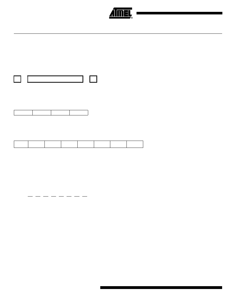
112
AVR Instruction Set
0856D–AVR–08/02
ROL – Rotate Left trough Carry
Description:
Shifts all bits in Rd one place to the left. The C Flag is shifted into bit 0 of Rd. Bit 7 is shifted into the C Flag. This operation,
combined with LSL, effectively multiplies multi-byte signed and unsigned values by two.
Operation:
Syntax:
Operands:
Program Counter:
(i)
ROL Rd
0
≤
d
≤
31
PC
←
PC + 1
16-bit Opcode: (see ADC Rd,Rd)
Status Register (SREG) and Boolean Formula:
H:
Rd3
S:
N
⊕
V, For signed tests.
V:
N
⊕
C (For N and C after the shift)
N:
R7
Set if MSB of the result is set; cleared otherwise.
Z:
R7
•
R6
•
R5
•
R4
•
R3
•
R2
•
R1
•
R0
Set if the result is $00; cleared otherwise.
C:
Rd7
Set if, before the shift, the MSB of Rd was set; cleared otherwise.
R (Result) equals Rd after the operation.
Example:
lsl
r18
; Multiply r19:r18 by two
rol
r19
; r19:r18 is a signed or unsigned two-byte integer
brcs
oneenc
; Branch if carry set
...
oneenc:
nop
; Branch destination (do nothing)
Words: 1 (2 bytes)
Cycles: 1
←
C
¨
b7 - - - - - - - - - - - - - - - - - - b0
←
C
0001
11dd
dddd
dddd
I
T
H
S
V
N
Z
C
–
–
⇔
⇔
⇔
⇔
⇔
⇔
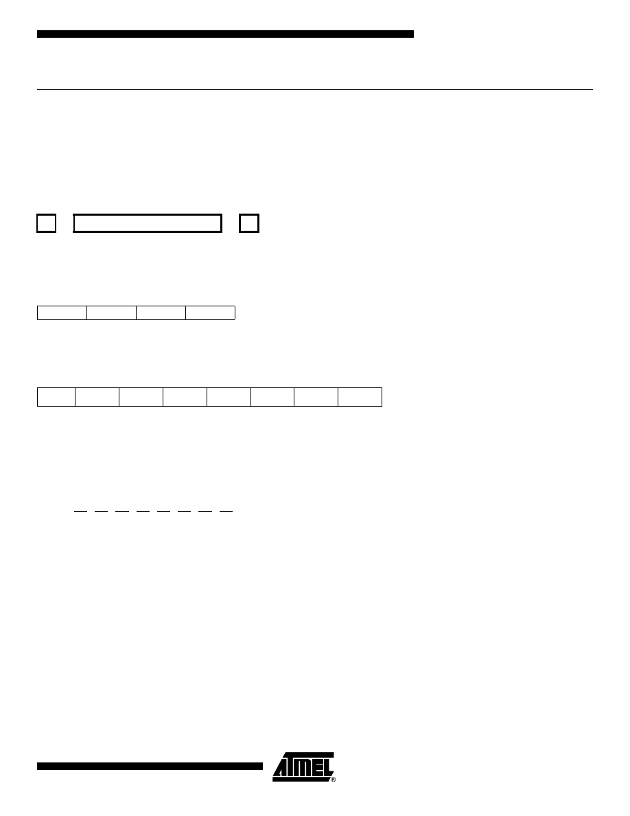
113
AVR Instruction Set
0856D–AVR–08/02
ROR – Rotate Right through Carry
Description:
Shifts all bits in Rd one place to the right. The C Flag is shifted into bit 7 of Rd. Bit 0 is shifted into the C Flag. This opera-
tion, combined with ASR, effectively divides multi-byte signed values by two. Combined with LSR it effectively divides multi-
byte unsigned values by two. The Carry Flag can be used to round the result.
Operation:
Syntax:
Operands:
Program Counter:
(i)
ROR Rd
0
≤
d
≤
31
PC
←
PC + 1
16-bit Opcode:
Status Register (SREG) and Boolean Formula:
S:
N
⊕
V, For signed tests.
V:
N
⊕
C (For N and C after the shift)
N:
R7
Set if MSB of the result is set; cleared otherwise.
Z:
R7
•
R6
•
R5
•
R4
•
R3
•
R2
•
R1
•
R0
Set if the result is $00; cleared otherwise.
C:
Rd0
Set if, before the shift, the LSB of Rd was set; cleared otherwise.
R (Result) equals Rd after the operation.
Example:
lsr
r19
; Divide r19:r18 by two
ror
r18
; r19:r18 is an unsigned two-byte integer
brcc
zeroenc1
; Branch if carry cleared
asr
r17
; Divide r17:r16 by two
ror
r16
; r17:r16 is a signed two-byte integer
brcc
zeroenc2
; Branch if carry cleared
...
zeroenc1:
nop
; Branch destination (do nothing)
...
→
C
→
b7 - - - - - - - - - - - - - - - - - - b0
→
C
1001
010d
dddd
0111
I
T
H
S
V
N
Z
C
–
–
–
⇔
⇔
⇔
⇔
⇔

114
AVR Instruction Set
0856D–AVR–08/02
zeroenc1:
nop
; Branch destination (do nothing)
Words: 1 (2 bytes)
Cycles: 1

115
AVR Instruction Set
0856D–AVR–08/02
SBC – Subtract with Carry
Description:
Subtracts two registers and subtracts with the C Flag and places the result in the destination register Rd.
Operation:
(i)
Rd
←
Rd - Rr - C
Syntax:
Operands:
Program Counter:
(i)
SBC Rd,Rr
0
≤
d
≤
31, 0
≤
r
≤
31
PC
←
PC + 1
16-bit Opcode:
Status Register and Boolean Formula:
H:
Rd3
•
Rr3 + Rr3
•
R3 + R3
•
Rd3
Set if there was a borrow from bit 3; cleared otherwise
S:
N
⊕
V, For signed tests.
V:
Rd7
•
Rr7
•
R7
+
Rd7
•
Rr7
•
R7
Set if two’s complement overflow resulted from the operation; cleared otherwise.
N:
R7
Set if MSB of the result is set; cleared otherwise.
Z:
R7
•
R6
•
R5
•
R4
•
R3
•
R2
•
R1
•
R0
•
Z
Previous value remains unchanged when the result is zero; cleared otherwise.
C:
Rd7
•
Rr7+ Rr7
•
R7 +R7
•
Rd7
Set if the absolute value of the contents of Rr plus previous carry is larger than the absolute value of the Rd; cleared
otherwise.
R (Result) equals Rd after the operation.
Example:
; Subtract r1:r0 from r3:r2
sub
r2,r0
; Subtract low byte
sbc
r3,r1
; Subtract with carry high byte
Words: 1 (2 bytes)
Cycles: 1
0000
10rd
dddd
rrrr
I
T
H
S
V
N
Z
C
–
–
⇔
⇔
⇔
⇔
⇔
⇔

116
AVR Instruction Set
0856D–AVR–08/02
SBCI – Subtract Immediate with Carry
Description:
Subtracts a constant from a register and subtracts with the C Flag and places the result in the destination register Rd.
Operation:
(i)
Rd
←
Rd - K - C
Syntax:
Operands:
Program Counter:
(i)
SBCI Rd,K
16
≤
d
≤
31, 0
≤
K
≤
255
PC
←
PC + 1
16-bit Opcode:
Status Register and Boolean Formula:
H:
Rd3
•
K3 + K3
•
R3 + R3
•
Rd3
Set if there was a borrow from bit 3; cleared otherwise
S:
N
⊕
V, For signed tests.
V:
Rd7
•
K7
•
R7
+
Rd7
•
K7
•
R7
Set if two’s complement overflow resulted from the operation; cleared otherwise.
N:
R7
Set if MSB of the result is set; cleared otherwise.
Z:
R7
•
R6
•
R5
•
R4
•
R3
•
R2
•
R1
•
R0
•
Z
Previous value remains unchanged when the result is zero; cleared otherwise.
C:
Rd7
•
K7+ K7
•
R7 +R7
•
Rd7
Set if the absolute value of the constant plus previous carry is larger than the absolute value of Rd; cleared other-
wise.
R (Result) equals Rd after the operation.
Example:
; Subtract $4F23 from r17:r16
subi
r16,$23
; Subtract low byte
sbci
r17,$4F
; Subtract with carry high byte
Words: 1 (2 bytes)
Cycles: 1
0100
KKKK
dddd
KKKK
I
T
H
S
V
N
Z
C
–
–
⇔
⇔
⇔
⇔
⇔
⇔

117
AVR Instruction Set
0856D–AVR–08/02
SBI – Set Bit in I/O Register
Description:
Sets a specified bit in an I/O Register. This instruction operates on the lower 32 I/O Registers – addresses 0-31.
Operation:
(i)
I/O(A,b)
←
1
Syntax:
Operands:
Program Counter:
(i)
SBI A,b
0
≤
A
≤
31, 0
≤
b
≤
7
PC
←
PC + 1
16-bit Opcode:
Status Register (SREG) and Boolean Formula:
Example:
out
$1E,r0
; Write EEPROM address
sbi
$1C,0
; Set read bit in EECR
in
r1,$1D
; Read EEPROM data
Words: 1 (2 bytes)
Cycles: 2
1001
1010
AAAA
Abbb
I
T
H
S
V
N
Z
C
–
–
–
–
–
–
–
–

118
AVR Instruction Set
0856D–AVR–08/02
SBIC – Skip if Bit in I/O Register is Cleared
Description:
This instruction tests a single bit in an I/O Register and skips the next instruction if the bit is cleared. This instruction oper-
ates on the lower 32 I/O Registers – addresses 0-31.
Operation:
(i)
If I/O(A,b) = 0 then PC
←
PC + 2 (or 3) else PC
←
PC + 1
Syntax:
Operands:
Program Counter:
(i)
SBIC A,b
0
≤
A
≤
31, 0
≤
b
≤
7
PC
←
PC + 1, Condition false - no skip
PC
←
PC + 2, Skip a one word instruction
PC
←
PC + 3, Skip a two word instruction
16-bit Opcode:
Status Register (SREG) and Boolean Formula:
Example:
e2wait:
sbic
$1C,1
; Skip next inst. if EEWE cleared
rjmp
e2wait
; EEPROM write not finished
nop
; Continue (do nothing)
Words: 1 (2 bytes)
Cycles: 1 if condition is false (no skip)
2 if condition is true (skip is executed) and the instruction skipped is 1 word
3 if condition is true (skip is executed) and the instruction skipped is 2 words
1001
1001
AAAA
Abbb
I
T
H
S
V
N
Z
C
–
–
–
–
–
–
–
–

119
AVR Instruction Set
0856D–AVR–08/02
SBIS – Skip if Bit in I/O Register is Set
Description:
This instruction tests a single bit in an I/O Register and skips the next instruction if the bit is set. This instruction operates on
the lower 32 I/O Registers – addresses 0-31.
Operation:
(i)
If I/O(A,b) = 1 then PC
←
PC + 2 (or 3) else PC
←
PC + 1
Syntax:
Operands:
Program Counter:
(i)
SBIS A,b
0
≤
A
≤
31, 0
≤
b
≤
7
PC
←
PC + 1, Condition false - no skip
PC
←
PC + 2, Skip a one word instruction
PC
←
PC + 3, Skip a two word instruction
16-bit Opcode:
Status Register (SREG) and Boolean Formula:
Example:
waitset:
sbis
$10,0
; Skip next inst. if bit 0 in Port D set
rjmp
waitset
; Bit not set
nop
; Continue (do nothing)
Words: 1 (2 bytes)
Cycles: 1 if condition is false (no skip)
2 if condition is true (skip is executed) and the instruction skipped is 1 word
3 if condition is true (skip is executed) and the instruction skipped is 2 words
1001
1011
AAAA
Abbb
I
T
H
S
V
N
Z
C
–
–
–
–
–
–
–
–

120
AVR Instruction Set
0856D–AVR–08/02
SBIW – Subtract Immediate from Word
Description:
Subtracts an immediate value (0-63) from a register pair and places the result in the register pair. This instruction operates
on the upper four register pairs, and is well suited for operations on the Pointer Registers.
This instruction is not available in all devices. Refer to the device specific instruction set summary.
Operation:
(i)
Rd+1:Rd
←
Rd+1:Rd - K
Syntax:
Operands:
Program Counter:
(i)
SBIW Rd+1:Rd,K
d
∈
{24,26,28,30}, 0
≤
K
≤
63
PC
←
PC + 1
16-bit Opcode:
Status Register (SREG) and Boolean Formula:
S:
N
⊕
V, For signed tests.
V:
Rdh7
•
R15
Set if two’s complement overflow resulted from the operation; cleared otherwise.
N:
R15
Set if MSB of the result is set; cleared otherwise.
Z:
R15
•
R14
•
R13
•
R12
•
R11
•
R10
•
R9
•
R8
•
R7
•
R6
•
R5
•
R4
•
R3
•
R2
•
R1
•
R0
Set if the result is $0000; cleared otherwise.
C:
R15
•
Rdh7
Set if the absolute value of K is larger than the absolute value of Rd; cleared otherwise.
R (Result) equals Rdh:Rdl after the operation (Rdh7-Rdh0 = R15-R8, Rdl7-Rdl0=R7-R0).
Example:
sbiw
r25:r24,1
; Subtract 1 from r25:r24
sbiw
YH:YL,63
; Subtract 63 from the Y-pointer(r29:r28)
Words: 1 (2 bytes)
Cycles: 2
1001
0111
KKdd
KKKK
I
T
H
S
V
N
Z
C
–
–
–
⇔
⇔
⇔
⇔
⇔

121
AVR Instruction Set
0856D–AVR–08/02
SBR – Set Bits in Register
Description:
Sets specified bits in register Rd. Performs the logical ORI between the contents of register Rd and a constant mask K and
places the result in the destination register Rd.
Operation:
(i)
Rd
←
Rd v K
Syntax:
Operands:
Program Counter:
(i)
SBR Rd,K
16
≤
d
≤
31, 0
≤
K
≤
255
PC
←
PC + 1
16-bit Opcode:
Status Register (SREG) and Boolean Formula:
S:
N
⊕
V, For signed tests.
V:
0
Cleared
N:
R7
Set if MSB of the result is set; cleared otherwise.
Z:
R7
•
R6
•
R5
•
R4
•
R3
•
R2
•
R1
•
R0
Set if the result is $00; cleared otherwise.
R (Result) equals Rd after the operation.
Example:
sbr
r16,3
; Set bits 0 and 1 in r16
sbr
r17,$F0
; Set 4 MSB in r17
Words: 1 (2 bytes)
Cycles: 1
0110
KKKK
dddd
KKKK
I
T
H
S
V
N
Z
C
–
–
–
⇔
0
⇔
⇔
–

122
AVR Instruction Set
0856D–AVR–08/02
SBRC – Skip if Bit in Register is Cleared
Description:
This instruction tests a single bit in a register and skips the next instruction if the bit is cleared.
Operation:
(i)
If Rr(b) = 0 then PC
←
PC + 2 (or 3) else PC
←
PC + 1
Syntax:
Operands:
Program Counter:
(i)
SBRC Rr,b
0
≤
r
≤
31, 0
≤
b
≤
7
PC
←
PC + 1, Condition false - no skip
PC
←
PC + 2, Skip a one word instruction
PC
←
PC + 3, Skip a two word instruction
16-bit Opcode:
Status Register (SREG) and Boolean Formula:
Example:
sub
r0,r1
; Subtract r1 from r0
sbrc
r0,7
; Skip if bit 7 in r0 cleared
sub
r0,r1
; Only executed if bit 7 in r0 not cleared
nop
; Continue (do nothing)
Words: 1 (2 bytes)
Cycles: 1 if condition is false (no skip)
2 if condition is true (skip is executed) and the instruction skipped is 1 word
3 if condition is true (skip is executed) and the instruction skipped is 2 words
1111
110r
rrrr
0bbb
I
T
H
S
V
N
Z
C
–
–
–
–
–
–
–
–
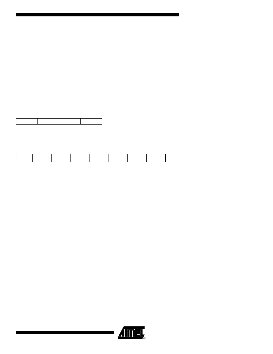
123
AVR Instruction Set
0856D–AVR–08/02
SBRS – Skip if Bit in Register is Set
Description:
This instruction tests a single bit in a register and skips the next instruction if the bit is set.
Operation:
(i)
If Rr(b) = 1 then PC
←
PC + 2 (or 3) else PC
←
PC + 1
Syntax:
Operands:
Program Counter:
(i)
SBRS Rr,b
0
≤
r
≤
31, 0
≤
b
≤
7
PC
←
PC + 1, Condition false - no skip
PC
←
PC + 2, Skip a one word instruction
PC
←
PC + 3, Skip a two word instruction
16-bit Opcode:
Status Register (SREG) and Boolean Formula:
Example:
sub
r0,r1
; Subtract r1 from r0
sbrs
r0,7
; Skip if bit 7 in r0 set
neg
r0
; Only executed if bit 7 in r0 not set
nop
; Continue (do nothing)
Words: 1 (2 bytes)
Cycles: 1 if condition is false (no skip)
2 if condition is true (skip is executed) and the instruction skipped is 1 word
3 if condition is true (skip is executed) and the instruction skipped is 2 words
1111
111r
rrrr
0bbb
I
T
H
S
V
N
Z
C
–
–
–
–
–
–
–
–

124
AVR Instruction Set
0856D–AVR–08/02
SEC – Set Carry Flag
Description:
Sets the Carry Flag (C) in SREG (Status Register).
Operation:
(i)
C
←
1
Syntax:
Operands:
Program Counter:
(i)
SEC
None
PC
←
PC + 1
16-bit Opcode:
Status Register (SREG) and Boolean Formula:
C:
1
Carry Flag set
Example:
sec
; Set Carry Flag
adc
r0,r1
; r0=r0+r1+1
Words: 1 (2 bytes)
Cycles: 1
1001
0100
0000
1000
I
T
H
S
V
N
Z
C
–
–
–
–
–
–
–
1

125
AVR Instruction Set
0856D–AVR–08/02
SEH – Set Half Carry Flag
Description:
Sets the Half Carry (H) in SREG (Status Register).
Operation:
(i)
H
←
1
Syntax:
Operands:
Program Counter:
(i)
SEH
None
PC
←
PC + 1
16-bit Opcode:
Status Register (SREG) and Boolean Formula:
H:
1
Half Carry Flag set
Example:
seh
; Set Half Carry Flag
Words: 1 (2 bytes)
Cycles: 1
1001
0100
0101
1000
I
T
H
S
V
N
Z
C
–
–
1
–
–
–
–
–

126
AVR Instruction Set
0856D–AVR–08/02
SEI – Set Global Interrupt Flag
Description:
Sets the Global Interrupt Flag (I) in SREG (Status Register). The instruction following SEI will be executed before any pend-
ing interrupts.
Operation:
(i)
I
←
1
Syntax:
Operands:
Program Counter:
(i)
SEI
None
PC
←
PC + 1
16-bit Opcode:
Status Register (SREG) and Boolean Formula:
I:
1
Global Interrupt Flag set
Example:
sei
; set global interrupt enable
sleep
; enter sleep, waiting for interrupt
; note: will enter sleep before any pending interrupt(s)
Words: 1 (2 bytes)
Cycles: 1
1001
0100
0111
1000
I
T
H
S
V
N
Z
C
1
–
–
–
–
–
–
–

127
AVR Instruction Set
0856D–AVR–08/02
SEN – Set Negative Flag
Description:
Sets the Negative Flag (N) in SREG (Status Register).
Operation:
(i)
N
←
1
Syntax:
Operands:
Program Counter:
(i)
SEN
None
PC
←
PC + 1
16-bit Opcode:
Status Register (SREG) and Boolean Formula:
N:
1
Negative Flag set
Example:
add
r2,r19
; Add r19 to r2
sen
; Set Negative Flag
Words: 1 (2 bytes)
Cycles: 1
1001
0100
0010
1000
I
T
H
S
V
N
Z
C
–
–
–
–
–
1
–
–

128
AVR Instruction Set
0856D–AVR–08/02
SER – Set all Bits in Register
Description:
Loads $FF directly to register Rd.
Operation:
(i)
Rd
←
$FF
Syntax:
Operands:
Program Counter:
(i)
SER Rd
16
≤
d
≤
31
PC
←
PC + 1
16-bit Opcode:
Status Register (SREG) and Boolean Formula:
Example:
clr
r16
; Clear r16
ser
r17
; Set r17
out
$18,r16
; Write zeros to Port B
nop
; Delay (do nothing)
out
$18,r17
; Write ones to Port B
Words: 1 (2 bytes)
Cycles: 1
1110
1111
dddd
1111
I
T
H
S
V
N
Z
C
–
–
–
–
–
–
–
–

129
AVR Instruction Set
0856D–AVR–08/02
SES – Set Signed Flag
Description:
Sets the Signed Flag (S) in SREG (Status Register).
Operation:
(i)
S
←
1
Syntax:
Operands:
Program Counter:
(i)
SES
None
PC
←
PC + 1
16-bit Opcode:
Status Register (SREG) and Boolean Formula:
S:
1
Signed Flag set
Example:
add
r2,r19
; Add r19 to r2
ses
; Set Negative Flag
Words: 1 (2 bytes)
Cycles: 1
1001
0100
0100
1000
I
T
H
S
V
N
Z
C
–
–
–
1
–
–
–
–

130
AVR Instruction Set
0856D–AVR–08/02
SET – Set T Flag
Description:
Sets the T Flag in SREG (Status Register).
Operation:
(i)
T
←
1
Syntax:
Operands:
Program Counter:
(i)
SET
None
PC
←
PC + 1
16-bit Opcode:
Status Register (SREG) and Boolean Formula:
T:
1
T Flag set
Example:
set
; Set T Flag
Words: 1 (2 bytes)
Cycles: 1
1001
0100
0110
1000
I
T
H
S
V
N
Z
C
–
1
–
–
–
–
–
–

131
AVR Instruction Set
0856D–AVR–08/02
SEV – Set Overflow Flag
Description:
Sets the Overflow Flag (V) in SREG (Status Register).
Operation:
(i)
V
←
1
Syntax:
Operands:
Program Counter:
(i)
SEV
None
PC
←
PC + 1
16-bit Opcode:
Status Register (SREG) and Boolean Formula:
V:
1
Overflow Flag set
Example:
add
r2,r19
; Add r19 to r2
sev
; Set Overflow Flag
Words: 1 (2 bytes)
Cycles: 1
1001
0100
0011
1000
I
T
H
S
V
N
Z
C
–
–
–
–
1
–
–
–

132
AVR Instruction Set
0856D–AVR–08/02
SEZ – Set Zero Flag
Description:
Sets the Zero Flag (Z) in SREG (Status Register).
Operation:
(i)
Z
←
1
Syntax:
Operands:
Program Counter:
(i)
SEZ
None
PC
←
PC + 1
16-bit Opcode:
Status Register (SREG) and Boolean Formula:
Z:
1
Zero Flag set
Example:
add
r2,r19
; Add r19 to r2
sez
; Set Zero Flag
Words: 1 (2 bytes)
Cycles: 1
1001
0100
0001
1000
I
T
H
S
V
N
Z
C
–
–
–
–
–
–
1
–
133
AVR Instruction Set
0856D–AVR–08/02
SLEEP
Description:
This instruction sets the circuit in sleep mode defined by the MCU Control Register.
Operation:
Refer to the device documentation for detailed description of SLEEP usage.
Syntax:
Operands:
Program Counter:
SLEEP
None
PC
←
PC + 1
16-bit Opcode:
Status Register (SREG) and Boolean Formula:
Example:
mov
r0,r11
; Copy r11 to r0
ldi
r16,(1<<SE)
; Enable sleep mode
out
MCUCR, r16
sleep
; Put MCU in sleep mode
Words: 1 (2 bytes)
Cycles: 1
1001
0101
1000
1000
I
T
H
S
V
N
Z
C
–
–
–
–
–
–
–
–

134
AVR Instruction Set
0856D–AVR–08/02
SPM – Store Program Memory
Description:
SPM can be used to erase a page in the Program memory, to write a page in the Program memory (that is already erased),
and to set Boot Loader Lock bits. In some devices, the Program memory can be written one word at a time, in other devices
an entire page can be programmed simultaneously after first filling a temporary page buffer. In all cases, the Program
memory must be erased one page at a time. When erasing the Program memory, the RAMPZ and Z-register are used as
page address. When writing the Program memory, the RAMPZ and Z-register are used as page or word address, and the
R1:R0 register pair is used as data
. When setting the Boot Loader Lock bits, the R1:R0 register pair is used as data.
Refer to the device documentation for detailed description of SPM usage. This instruction can address the entire Program
memory.
This instruction is not available in all devices. Refer to the device specific instruction set summary.
Note:
1. R1 determines the instruction high byte, and R0 determines the instruction low byte.
Operation:
Comment:
(i)
(RAMPZ:Z)
←
$ffff
Erase Program memory page
(ii)
(RAMPZ:Z)
←
R1:R0
Write Program memory word
(iii)
(RAMPZ:Z)
←
R1:R0
Write temporary page buffer
(iv)
(RAMPZ:Z)
←
TEMP
Write temporary page buffer to Program memory
(v)
BLBITS
←
R1:R0
Set Boot Loader Lock bits
Syntax:
Operands:
Program Counter:
(i)-(v)
SPM
None
PC
←
PC + 1
16-bit Opcode:
Status Register (SREG) and Boolean Formula:
Example:
;This example shows SPM write of one page for devices with page write
;- the routine writes one page of data from RAM to Flash
;
the first data location in RAM is pointed to by the Y-pointer
;
the first data location in Flash is pointed to by the Z-pointer
;- error handling is not included
;- the routine must be placed inside the boot space
;
(at least the do_spm sub routine)
;- registers used: r0, r1, temp1, temp2, looplo, loophi, spmcrval
;
(temp1, temp2, looplo, loophi, spmcrval must be defined by the user)
;
storing and restoring of registers is not included in the routine
;
register usage can be optimized at the expense of code size
.equPAGESIZEB = PAGESIZE*2;PAGESIZEB is page size in BYTES, not words
.org SMALLBOOTSTART
write_page:
1001
0101
1110
1000
I
T
H
S
V
N
Z
C
–
–
–
–
–
–
–
–

135
AVR Instruction Set
0856D–AVR–08/02
;page erase
ldispmcrval, (1<<PGERS) + (1<<SPMEN)
calldo_spm
;transfer data from RAM to Flash page buffer
ldilooplo, low(PAGESIZEB);init loop variable
ldiloophi, high(PAGESIZEB);not required for PAGESIZEB<=256
wrloop:ldr0, Y+
ldr1, Y+
ldispmcrval, (1<<SPMEN)
calldo_spm
adiwZH:ZL, 2
sbiwloophi:looplo, 2;use subi for PAGESIZEB<=256
brnewrloop
;execute page write
subiZL, low(PAGESIZEB);restore pointer
sbciZH, high(PAGESIZEB);not required for PAGESIZEB<=256
ldispmcrval, (1<<PGWRT) + (1<<SPMEN)
calldo_spm
;read back and check, optional
ldilooplo, low(PAGESIZEB);init loop variable
ldiloophi, high(PAGESIZEB);not required for PAGESIZEB<=256
subiYL, low(PAGESIZEB);restore pointer
sbciYH, high(PAGESIZEB)
rdloop:lpmr0, Z+
ldr1, Y+
cpser0, r1
jmperror
sbiwloophi:looplo, 2;use subi for PAGESIZEB<=256
brnerdloop
;return
ret
do_spm:
;input: spmcrval determines SPM action
;disable interrupts if enabled, store status
intemp2, SREG
cli
;check for previous SPM complete
wait:intemp1, SPMCR
sbrctemp1, SPMEN
rjmpwait
;SPM timed sequence
outSPMCR, spmcrval
spm
;restore SREG (to enable interrupts if originally enabled)
outSREG, temp2

136
AVR Instruction Set
0856D–AVR–08/02
ret
Words: 1 (2 bytes)
Cycles: depends on the operation

137
AVR Instruction Set
0856D–AVR–08/02
ST – Store Indirect From Register to Data Space using Index X
Description:
Stores one byte indirect from a register to data space. For parts with SRAM, the data space consists of the Register File,
I/O memory and internal SRAM (and external SRAM if applicable). For parts without SRAM, the data space consists of the
Register File only. The EEPROM has a separate address space.
The data location is pointed to by the X (16 bits) Pointer Register in the Register File. Memory access is limited to the cur-
rent data segment of 64K bytes. To access another data segment in devices with more than 64K bytes data space, the
RAMPX in register in the I/O area has to be changed.
The X-pointer Register can either be left unchanged by the operation, or it can be post-incremented or pre-decremented.
These features are especially suited for accessing arrays, tables, and Stack Pointer usage of the X-pointer Register. Note
that only the low byte of the X-pointer is updated in devices with no more than 256 bytes data space. For such devices, the
high byte of the pointer is not used by this instruction and can be used for other purposes. The RAMPX Register in the I/O
area is updated in parts with more than 64K bytes data space or more than 64K bytes Program memory, and the incre-
ment/ decrement is added to the entire 24-bit address on such devices.
Not all variants of this instruction is available in all devices. Refer to the device specific instruction set summary.
The result of these combinations is undefined:
ST X+, r26
ST X+, r27
ST -X, r26
ST -X, r27
Using the X-pointer:
Operation:
Comment:
(i)
(X)
←
Rr
X: Unchanged
(ii)
(X)
←
Rr
X
←
X+1
X: Post incremented
(iii)
X
←
X - 1
(X)
←
Rr
X: Pre decremented
Syntax:
Operands:
Program Counter:
(i)
ST X, Rr
0
≤
r
≤
31
PC
←
PC + 1
(ii)
ST X+, Rr
0
≤
r
≤
31
PC
←
PC + 1
(iii)
ST -X, Rr
0
≤
r
≤
31
PC
←
PC + 1
16-bit Opcode :
Status Register (SREG) and Boolean Formula:
(i)
1001
001r
rrrr
1100
(ii)
1001
001r
rrrr
1101
(iii)
1001
001r
rrrr
1110
I
T
H
S
V
N
Z
C
–
–
–
–
–
–
–
–

138
AVR Instruction Set
0856D–AVR–08/02
Example:
clr
r27
; Clear X high byte
ldi
r26,$60
; Set X low byte to $60
st
X+,r0
; Store r0 in data space loc. $60(X post inc)
st
X,r1
; Store r1 in data space loc. $61
ldi
r26,$63
; Set X low byte to $63
st
X,r2
; Store r2 in data space loc. $63
st
-X,r3
; Store r3 in data space loc. $62(X pre dec)
Words: 1 (2 bytes)
Cycles: 2

139
AVR Instruction Set
0856D–AVR–08/02
ST (STD) – Store Indirect From Register to Data Space using Index Y
Description:
Stores one byte indirect with or without displacement from a register to data space. For parts with SRAM, the data space
consists of the Register File, I/O memory and internal SRAM (and external SRAM if applicable). For parts without SRAM,
the data space consists of the Register File only. The EEPROM has a separate address space.
The data location is pointed to by the Y (16 bits) Pointer Register in the Register File. Memory access is limited to the cur-
rent data segment of 64K bytes. To access another data segment in devices with more than 64K bytes data space, the
RAMPY in register in the I/O area has to be changed.
The Y-pointer Register can either be left unchanged by the operation, or it can be post-incremented or pre-decremented.
These features are especially suited for accessing arrays, tables, and Stack Pointer usage of the Y-pointer Register. Note
that only the low byte of the Y-pointer is updated in devices with no more than 256 bytes data space. For such devices, the
high byte of the pointer is not used by this instruction and can be used for other purposes. The RAMPY Register in the I/O
area is updated in parts with more than 64K bytes data space or more than 64K bytes Program memory, and the incre-
ment/ decrement/displacement is added to the entire 24-bit address on such devices.
Not all variants of this instruction is available in all devices. Refer to the device specific instruction set summary.
The result of these combinations is undefined:
ST Y+, r28
ST Y+, r29
ST -Y, r28
ST -Y, r29
Using the Y-pointer:
Operation:
Comment:
(i)
(Y)
←
Rr
Y: Unchanged
(ii)
(Y)
←
Rr
Y
←
Y+1
Y: Post incremented
(iii)
Y
←
Y - 1
(Y)
←
Rr
Y: Pre decremented
(iiii)
(Y+q)
←
Rr
Y: Unchanged, q: Displacement
Syntax:
Operands:
Program Counter:
(i)
ST Y, Rr
0
≤
r
≤
31
PC
←
PC + 1
(ii)
ST Y+, Rr
0
≤
r
≤
31
PC
←
PC + 1
(iii)
ST -Y, Rr
0
≤
r
≤
31
PC
←
PC + 1
(iiii)
STD Y+q, Rr
0
≤
r
≤
31, 0
≤
q
≤
63
PC
←
PC + 1
16-bit Opcode:
(i)
1000
001r
rrrr
1000
(ii)
1001
001r
rrrr
1001
(iii)
1001
001r
rrrr
1010
(iiii)
10q0
qq1r
rrrr
1qqq

140
AVR Instruction Set
0856D–AVR–08/02
Status Register (SREG) and Boolean Formula:
Example:
clr
r29
; Clear Y high byte
ldi
r28,$60
; Set Y low byte to $60
st
Y+,r0
; Store r0 in data space loc. $60(Y post inc)
st
Y,r1
; Store r1 in data space loc. $61
ldi
r28,$63
; Set Y low byte to $63
st
Y,r2
; Store r2 in data space loc. $63
st
-Y,r3
; Store r3 in data space loc. $62(Y pre dec)
std
Y+2,r4
; Store r4 in data space loc. $64
Words: 1 (2 bytes)
Cycles: 2
I
T
H
S
V
N
Z
C
–
–
–
–
–
–
–
–

141
AVR Instruction Set
0856D–AVR–08/02
ST (STD) – Store Indirect From Register to Data Space using Index Z
Description:
Stores one byte indirect with or without displacement from a register to data space. For parts with SRAM, the data space
consists of the Register File, I/O memory and internal SRAM (and external SRAM if applicable). For parts without SRAM,
the data space consists of the Register File only. The EEPROM has a separate address space.
The data location is pointed to by the Z (16 bits) Pointer Register in the Register File. Memory access is limited to the cur-
rent data segment of 64K bytes. To access another data segment in devices with more than 64K bytes data space, the
RAMPZ in register in the I/O area has to be changed.
The Z-pointer Register can either be left unchanged by the operation, or it can be post-incremented or pre-decremented.
These features are especially suited for Stack Pointer usage of the Z-pointer Register, however because the Z-pointer
Register can be used for indirect subroutine calls, indirect jumps and table lookup, it is often more convenient to use the X
or Y-pointer as a dedicated Stack Pointer. Note that only the low byte of the Z-pointer is updated in devices with no more
than 256 bytes data space. For such devices, the high byte of the pointer is not used by this instruction and can be used for
other purposes. The RAMPZ Register in the I/O area is updated in parts with more than 64K bytes data space or more than
64K bytes Program memory, and the increment/decrement/displacement is added to the entire 24-bit address on such
devices.
Not all variants of this instruction is available in all devices. Refer to the device specific instruction set summary.
The result of these combinations is undefined:
ST Z+, r30
ST Z+, r31
ST -Z, r30
ST -Z, r31
Using the Z-pointer:
Operation:
Comment:
(i)
(Z)
←
Rr
Z: Unchanged
(ii)
(Z)
←
Rr
Z
←
Z+1
Z: Post incremented
(iii)
Z
←
Z - 1
(Z)
←
Rr
Z: Pre decremented
(iiii)
(Z+q)
←
Rr
Z: Unchanged, q: Displacement
Syntax:
Operands:
Program Counter:
(i)
ST Z, Rr
0
≤
r
≤
31
PC
←
PC + 1
(ii)
ST Z+, Rr
0
≤
r
≤
31
PC
←
PC + 1
(iii)
ST -Z, Rr
0
≤
r
≤
31
PC
←
PC + 1
(iiii)
STD Z+q, Rr
0
≤
r
≤
31, 0
≤
q
≤
63
PC
←
PC + 1

142
AVR Instruction Set
0856D–AVR–08/02
16-bit Opcode :
Status Register (SREG) and Boolean Formula:
Example:
clr
r31
; Clear Z high byte
ldi
r30,$60
; Set Z low byte to $60
st
Z+,r0
; Store r0 in data space loc. $60(Z post inc)
st
Z,r1
; Store r1 in data space loc. $61
ldi
r30,$63
; Set Z low byte to $63
st
Z,r2
; Store r2 in data space loc. $63
st
-Z,r3
; Store r3 in data space loc. $62(Z pre dec)
std
Z+2,r4
; Store r4 in data space loc. $64
Words: 1 (2 bytes)
Cycles: 2
(i)
1000
001r
rrrr
0000
(ii)
1001
001r
rrrr
0001
(iii)
1001
001r
rrrr
0010
(iiii)
10q0
qq1r
rrrr
0qqq
I
T
H
S
V
N
Z
C
–
–
–
–
–
–
–
–
143
AVR Instruction Set
0856D–AVR–08/02
STS – Store Direct to Data Space
Description:
Stores one byte from a Register to the data space. For parts with SRAM, the data space consists of the Register File, I/O
memory and internal SRAM (and external SRAM if applicable). For parts without SRAM, the data space consists of the
Register File only. The EEPROM has a separate address space.
A 16-bit address must be supplied. Memory access is limited to the current data segment of 64K bytes. The STS instruction
uses the RAMPD Register to access memory above 64K bytes. To access another data segment in devices with more than
64K bytes data space, the RAMPD in register in the I/O area has to be changed.
This instruction is not available in all devices. Refer to the device specific instruction set summary.
Operation:
(i)
(k)
←
Rr
Syntax:
Operands:
Program Counter:
(i)
STS k,Rr
0
≤
r
≤
31, 0
≤
k
≤
65535
PC
←
PC + 2
32-bit Opcode:
Status Register (SREG) and Boolean Formula:
Example:
lds
r2,$FF00
; Load r2 with the contents of data space location $FF00
add
r2,r1
; add r1 to r2
sts
$FF00,r2
; Write back
Words: 2 (4 bytes)
Cycles: 2
1001
001d
dddd
0000
kkkk
kkkk
kkkk
kkkk
I
T
H
S
V
N
Z
C
–
–
–
–
–
–
–
–

144
AVR Instruction Set
0856D–AVR–08/02
SUB – Subtract without Carry
Description:
Subtracts two registers and places the result in the destination register Rd.
Operation:
(i)
Rd
←
Rd - Rr
Syntax:
Operands:
Program Counter:
(i)
SUB Rd,Rr
0
≤
d
≤
31, 0
≤
r
≤
31
PC
←
PC + 1
16-bit Opcode:
Status Register and Boolean Formula:
H:
Rd3
•
Rr3 +Rr3
•
R3 +R3
•
Rd3
Set if there was a borrow from bit 3; cleared otherwise
S:
N
⊕
V, For signed tests.
V:
Rd7
•
Rr7
•
R7
+
Rd7
•
Rr7
•
R7
Set if two’s complement overflow resulted from the operation; cleared otherwise.
N:
R7
Set if MSB of the result is set; cleared otherwise.
Z:
R7
•
R6
•
R5
•
R4
•
R3
•
R2
•
R1
•
R0
Set if the result is $00; cleared otherwise.
C:
Rd7
•
Rr7 +Rr7
•
R7 +R7
•
Rd7
Set if the absolute value of the contents of Rr is larger than the absolute value of Rd; cleared otherwise.
R (Result) equals Rd after the operation.
Example:
sub
r13,r12
; Subtract r12 from r13
brne
noteq
; Branch if r12<>r13
...
noteq:
nop
; Branch destination (do nothing)
Words: 1 (2 bytes)
Cycles: 1
0001
10rd
dddd
rrrr
I
T
H
S
V
N
Z
C
–
–
⇔
⇔
⇔
⇔
⇔
⇔

145
AVR Instruction Set
0856D–AVR–08/02
SUBI – Subtract Immediate
Description:
Subtracts a register and a constant and places the result in the destination register Rd. This instruction is working on Reg-
ister R16 to R31 and is very well suited for operations on the X, Y and Z-pointers.
Operation:
(i)
Rd
←
Rd - K
Syntax:
Operands:
Program Counter:
(i)
SUBI Rd,K
16
≤
d
≤
31, 0
≤
K
≤
255
PC
←
PC + 1
16-bit Opcode:
Status Register and Boolean Formula:
H:
Rd3
•
K3+K3
•
R3 +R3
•
Rd3
Set if there was a borrow from bit 3; cleared otherwise
S:
N
⊕
V, For signed tests.
V:
Rd7
•
K7
•
R7 +Rd7
•
K7
•
R7
Set if two’s complement overflow resulted from the operation; cleared otherwise.
N:
R7
Set if MSB of the result is set; cleared otherwise.
Z:
R7
•
R6
•
R5
•
R4
•
R3
•
R2
•
R1
•
R0
Set if the result is $00; cleared otherwise.
C:
Rd7
•
K7 +K7
•
R7 +R7
•
Rd7
Set if the absolute value of K is larger than the absolute value of Rd; cleared otherwise.
R (Result) equals Rd after the operation.
Example:
subi
r22,$11
; Subtract $11 from r22
brne
noteq
; Branch if r22<>$11
...
noteq:
nop
; Branch destination (do nothing)
Words: 1 (2 bytes)
Cycles: 1
0101
KKKK
dddd
KKKK
I
T
H
S
V
N
Z
C
–
–
⇔
⇔
⇔
⇔
⇔
⇔

146
AVR Instruction Set
0856D–AVR–08/02
SWAP – Swap Nibbles
Description:
Swaps high and low nibbles in a register.
Operation:
(i)
R(7:4)
←
Rd(3:0), R(3:0)
←
Rd(7:4)
Syntax:
Operands:
Program Counter:
(i)
SWAP Rd
0
≤
d
≤
31
PC
←
PC + 1
16-bit Opcode:
Status Register and Boolean Formula:
R (Result) equals Rd after the operation.
Example:
inc
r1
; Increment r1
swap
r1
; Swap high and low nibble of r1
inc
r1
; Increment high nibble of r1
swap
r1
; Swap back
Words: 1 (2 bytes)
Cycles: 1
1001
010d
dddd
0010
I
T
H
S
V
N
Z
C
–
–
–
–
–
–
–
–

147
AVR Instruction Set
0856D–AVR–08/02
TST – Test for Zero or Minus
Description:
Tests if a register is zero or negative. Performs a logical AND between a register and itself. The register will remain
unchanged.
Operation:
(i)
Rd
←
Rd
•
Rd
Syntax:
Operands:
Program Counter:
(i)
TST Rd
0
≤
d
≤
31
PC
←
PC + 1
16-bit Opcode: (see AND Rd, Rd)
Status Register and Boolean Formula:
S:
N
⊕
V, For signed tests.
V:
0
Cleared
N:
R7
Set if MSB of the result is set; cleared otherwise.
Z:
R7
•
R6
•
R5
•
R4
•
R3
•
R2
•
R1
•
R0
Set if the result is $00; cleared otherwise.
R (Result) equals Rd.
Example:
tst
r0
; Test r0
breq
zero
; Branch if r0=0
...
zero:
nop
; Branch destination (do nothing)
Words: 1 (2 bytes)
Cycles: 1
0010
00dd
dddd
dddd
I
T
H
S
V
N
Z
C
–
–
–
⇔
0
⇔
⇔
–
148
AVR Instruction Set
0856D–AVR–08/02
WDR – Watchdog Reset
Description:
This instruction resets the Watchdog Timer. This instruction must be executed within a limited time given by the WD pres-
caler. See the Watchdog Timer hardware specification.
Operation:
(i)
WD timer restart.
Syntax:
Operands:
Program Counter:
(i)
WDR
None
PC
←
PC + 1
16-bit Opcode:
Status Register and Boolean Formula:
Example:
wdr
; Reset watchdog timer
Words: 1 (2 bytes)
Cycles: 1
1001
0101
1010
1000
I
T
H
S
V
N
Z
C
–
–
–
–
–
–
–
–

Printed on recycled paper.
© Atmel Corporation 2002.
Atmel Corporation makes no warranty for the use of its products, other than those expressly contained in the Company’s standard warranty
which is detailed in Atmel’s Terms and Conditions located on the Company’s web site. The Company assumes no responsibility for any errors
which may appear in this document, reserves the right to change devices or specifications detailed herein at any time without notice, and does
not make any commitment to update the information contained herein. No licenses to patents or other intellectual property of Atmel are granted
by the Company in connection with the sale of Atmel products, expressly or by implication. Atmel’s products are not authorized for use as critical
components in life support devices or systems.
Atmel Headquarters
Atmel Operations
Corporate Headquarters
2325 Orchard Parkway
San Jose, CA 95131
TEL 1(408) 441-0311
FAX 1(408) 487-2600
Europe
Atmel Sarl
Route des Arsenaux 41
Case Postale 80
CH-1705 Fribourg
Switzerland
TEL (41) 26-426-5555
FAX (41) 26-426-5500
Asia
Room 1219
Chinachem Golden Plaza
77 Mody Road Tsimhatsui
East Kowloon
Hong Kong
TEL (852) 2721-9778
FAX (852) 2722-1369
Japan
9F, Tonetsu Shinkawa Bldg.
1-24-8 Shinkawa
Chuo-ku, Tokyo 104-0033
Japan
TEL (81) 3-3523-3551
FAX (81) 3-3523-7581
Memory
2325 Orchard Parkway
San Jose, CA 95131
TEL 1(408) 441-0311
FAX 1(408) 436-4314
Microcontrollers
2325 Orchard Parkway
San Jose, CA 95131
TEL 1(408) 441-0311
FAX 1(408) 436-4314
La Chantrerie
BP 70602
44306 Nantes Cedex 3, France
TEL (33) 2-40-18-18-18
FAX (33) 2-40-18-19-60
ASIC/ASSP/Smart Cards
Zone Industrielle
13106 Rousset Cedex, France
TEL (33) 4-42-53-60-00
FAX (33) 4-42-53-60-01
1150 East Cheyenne Mtn. Blvd.
Colorado Springs, CO 80906
TEL 1(719) 576-3300
FAX 1(719) 540-1759
Scottish Enterprise Technology Park
Maxwell Building
East Kilbride G75 0QR, Scotland
TEL (44) 1355-803-000
FAX (44) 1355-242-743
RF/Automotive
Theresienstrasse 2
Postfach 3535
74025 Heilbronn, Germany
TEL (49) 71-31-67-0
FAX (49) 71-31-67-2340
1150 East Cheyenne Mtn. Blvd.
Colorado Springs, CO 80906
TEL 1(719) 576-3300
FAX 1(719) 540-1759
Biometrics/Imaging/Hi-Rel MPU/
High Speed Converters/RF Datacom
Avenue de Rochepleine
BP 123
38521 Saint-Egreve Cedex, France
TEL (33) 4-76-58-30-00
FAX (33) 4-76-58-34-80
literature@atmel.com
Web Site
http://www.atmel.com
0856D–AVR–08/02
0M
ATMEL
®
and AVR
®
are the registered trademarks of Atmel.
Other terms and product names may be the trademarks of others.
Document Outline
- Instruction Set Nomenclature
- I/O Registers
- The Program and Data Addressing Modes
- Conditional Branch Summary
- Complete Instruction Set Summary
- ADC – Add with Carry
- ADD – Add without Carry
- ADIW – Add Immediate to Word
- AND – Logical AND
- ANDI – Logical AND with Immediate
- ASR – Arithmetic Shift Right
- BCLR – Bit Clear in SREG
- BLD – Bit Load from the T Flag in SREG to a Bit in Register
- BRBC – Branch if Bit in SREG is Cleared
- BRBS – Branch if Bit in SREG is Set
- BRCC – Branch if Carry Cleared
- BRCS – Branch if Carry Set
- BREAK – Break
- BREQ – Branch if Equal
- BRGE – Branch if Greater or Equal (Signed)
- BRHC – Branch if Half Carry Flag is Cleared
- BRHS – Branch if Half Carry Flag is Set
- BRID – Branch if Global Interrupt is Disabled
- BRIE – Branch if Global Interrupt is Enabled
- BRLO – Branch if Lower (Unsigned)
- BRLT – Branch if Less Than (Signed)
- BRMI – Branch if Minus
- BRNE – Branch if Not Equal
- BRPL – Branch if Plus
- BRSH – Branch if Same or Higher (Unsigned)
- BRTC – Branch if the T Flag is Cleared
- BRTS – Branch if the T Flag is Set
- BRVC – Branch if Overflow Cleared
- BRVS – Branch if Overflow Set
- BSET – Bit Set in SREG
- BST – Bit Store from Bit in Register to T Flag in SREG
- CALL – Long Call to a Subroutine
- CBI – Clear Bit in I/O Register
- CBR – Clear Bits in Register
- CLC – Clear Carry Flag
- CLH – Clear Half Carry Flag
- CLI – Clear Global Interrupt Flag
- CLN – Clear Negative Flag
- CLR – Clear Register
- CLS – Clear Signed Flag
- CLT – Clear T Flag
- CLV – Clear Overflow Flag
- CLZ – Clear Zero Flag
- COM – One’s Complement
- CP – Compare
- CPC – Compare with Carry
- CPI – Compare with Immediate
- CPSE – Compare Skip if Equal
- DEC – Decrement
- EICALL – Extended Indirect Call to Subroutine
- EIJMP – Extended Indirect Jump
- ELPM – Extended Load Program Memory
- EOR – Exclusive OR
- FMUL – Fractional Multiply Unsigned
- FMULS – Fractional Multiply Signed
- FMULSU – Fractional Multiply Signed with Unsigned
- ICALL – Indirect Call to Subroutine
- IJMP – Indirect Jump
- IN - Load an I/O Location to Register
- INC – Increment
- JMP – Jump
- LD – Load Indirect from Data Space to Register using Index X
- LD (LDD) – Load Indirect from Data Space to Register using Index Y
- LD (LDD) – Load Indirect From Data Space to Register using Index Z
- LDI – Load Immediate
- LDS – Load Direct from Data Space
- LPM – Load Program Memory
- LSL – Logical Shift Left
- LSR – Logical Shift Right
- MOV – Copy Register
- MOVW – Copy Register Word
- MUL – Multiply Unsigned
- MULS – Multiply Signed
- MULSU – Multiply Signed with Unsigned
- NEG – Two’s Complement
- NOP – No Operation
- OR – Logical OR
- ORI – Logical OR with Immediate
- OUT – Store Register to I/O Location
- POP – Pop Register from Stack
- PUSH – Push Register on Stack
- RCALL – Relative Call to Subroutine
- RET – Return from Subroutine
- RETI – Return from Interrupt
- RJMP – Relative Jump
- ROL – Rotate Left trough Carry
- ROR – Rotate Right through Carry
- SBC – Subtract with Carry
- SBCI – Subtract Immediate with Carry
- SBI – Set Bit in I/O Register
- SBIC – Skip if Bit in I/O Register is Cleared
- SBIS – Skip if Bit in I/O Register is Set
- SBIW – Subtract Immediate from Word
- SBR – Set Bits in Register
- SBRC – Skip if Bit in Register is Cleared
- SBRS – Skip if Bit in Register is Set
- SEC – Set Carry Flag
- SEH – Set Half Carry Flag
- SEI – Set Global Interrupt Flag
- SEN – Set Negative Flag
- SER – Set all Bits in Register
- SES – Set Signed Flag
- SET – Set T Flag
- SEV – Set Overflow Flag
- SEZ – Set Zero Flag
- SLEEP
- SPM – Store Program Memory
- ST – Store Indirect From Register to Data Space using Index X
- ST (STD) – Store Indirect From Register to Data Space using Index Y
- ST (STD) – Store Indirect From Register to Data Space using Index Z
- STS – Store Direct to Data Space
- SUB – Subtract without Carry
- SUBI – Subtract Immediate
- SWAP – Swap Nibbles
- TST – Test for Zero or Minus
- WDR – Watchdog Reset
Wyszukiwarka
Podobne podstrony:
Chapter Five Instruction Set Architecture
Instruction set
Instruction set
Instrukcja obsługi wkretarka LUX TOOLS ABS 18LiC Set
wykład 6 instrukcje i informacje zwrotne
Instrumenty rynku kapitałowego VIII
05 Instrukcje warunkoweid 5533 ppt
Instrukcja Konwojowa
2 Instrumenty marketingu mix
Promocja jako instrument marketingowy 1
Promocja jako instrument marketingowy
więcej podobnych podstron