Gas Motorventil
Motorized valves for gas
Vanne à gaz motorisée
VK
3.1.4 Edition 4.99 D/GB/F
Gas-Motorventil VK..
Automatisches Absperrventil Klasse A
nach EN 161
Robuste Ausführung lange Lebens-
dauer
Stromsparend durch Motorselbstab-
schaltung
Ein- oder zweistufig mit Meldeschalter
lieferbar
Ventilgehäuse aus GGG 40 lieferbar
Explosionsgeschütztes Ventiloberteil
lieferbar
EG-Baumuster geprüft und zertifiziert
2
Anwendung
Zum Sichern, Regeln und Steuern der
Gas- und Luftzufuhr zu Gasbrennern und
Gasgeräten, auch für zweistufige Betriebs-
weise. Das VK..G mit GGG 40-Gehäuse
erfüllt die Anforderungen nach TRD 412,
Absatz 4.2 (Einsatz in Freiluftanlagen),
Absatz 5.1 (Absperreinrichtung außerhalb
des Kesselaufstellungsraumes) und GUV
17.4 (Einsatz in Deponieanlagen).
Für explosionsgefährdete Bereiche Zone
1 und 2 empfiehlt sich das VK..X, z.B. in
Lackfabriken, Lackierereibetrieben, Raffi-
nerien, chemischen Fabriken, Kläranlagen,
auf Deponien, Gas-Öl-Förderanlagen usw.
Motorised valve for gas VK..
Automatic shut-off valve class A to EN
161
Robust construction, long service life
Economical through automatic motor
shut-off
Available as one or two-step version
with position indicator
Available with GGG 40 valve housing
Available with explosion-proof valve
upper section
EC type tested and certified
Application
For safeguarding, controlling and
regulating the gas and air flow to burners
and devices, including two-step opera-
tion. The VK..G with GGG 40 housing
complies with the requirements of TRD
412, Paragraph 4.2 (Use in Open-Air
Installations), Paragraph 5.1 (Shut-Off
Device Outside the Boiler Room) and
GUV 17.4 (Use in Landfill Installations).
The VK..X version is recommended for
hazardous areas zone 1 and 2, e.g. in
paint factories, paint shops, refineries,
chemical plants, sewage treatment
plants, waste dumps (landfill sites) and
gas/oil delivery lines etc.
Vanne à gaz motorisée VK..
Vanne d'arrêt automatique classe A
selon EN 161
Construction robuste, longue durée
de vie
Economique en consommation de
courant grâce à l'arrêt automatique
du moteur
Versions à un étage ou deux étages
avec indicateur de position
Version avec boîtier de vanne en
GGG 40
Version avec boîtier supérieur anti-
déflagrant
Testée par examen CE de type et
certifiée
Application
Arrêt, régulation et réglage de l'arrivée du
gaz et de l'air aux brûleurs et aux appareils
à gaz, y compris pour le fonctionnement à
deux étages. La vanne VK..G à corps en
GGG 40 satisfait les spécifications selon
TRD 412, alinéa 4.2 (utilisation dans les
installations à l'air libre), alinéa 5.1 (disposi-
tif d'arrêt en dehors du local d'implantation
de la chaudière) et GUV 17.4 (utilisation sur
décharges).
Pour les zones comportant risque d'explo-
sion à coefficient zone 1 et 2, nous recom-
mandons la vanne VK..X ; par exemple,
dans les fabriques de peintures, ateliers de
peinture, raffineries, industries chimiques,
stations d'épuration, sur les décharges,
installations de transport de gaz et de
pétrole, etc.
Fig. 1
Fig. 2
Fig. 3

3
Valve housing:
AlSi on VK..A DN 40 to DN 250 (Fig. 1+2),
GGG 40 on VK..G DN 50 to DN 200 (Fig.3),
epoxy powder-coated on inside and out-
side.
The two housings can be combined with
various upper sections.
Max. inlet pressure: see Table Specifica-
tions.
VK..G models are pressure-resistant up to
8 bar and pressure surge-resistant up to
20 bar.
Valve upper section: AlSi
Valve disc seal:
Perbunan up to DN 150
Polyurethane DN 200
Viton as variation DN 40 - 150
Complying with standard to EN 161, class
A, group 2.
Measuring connection or pilot gas supply
tapping connection Rp 1/4 at both ends
in the input and output.
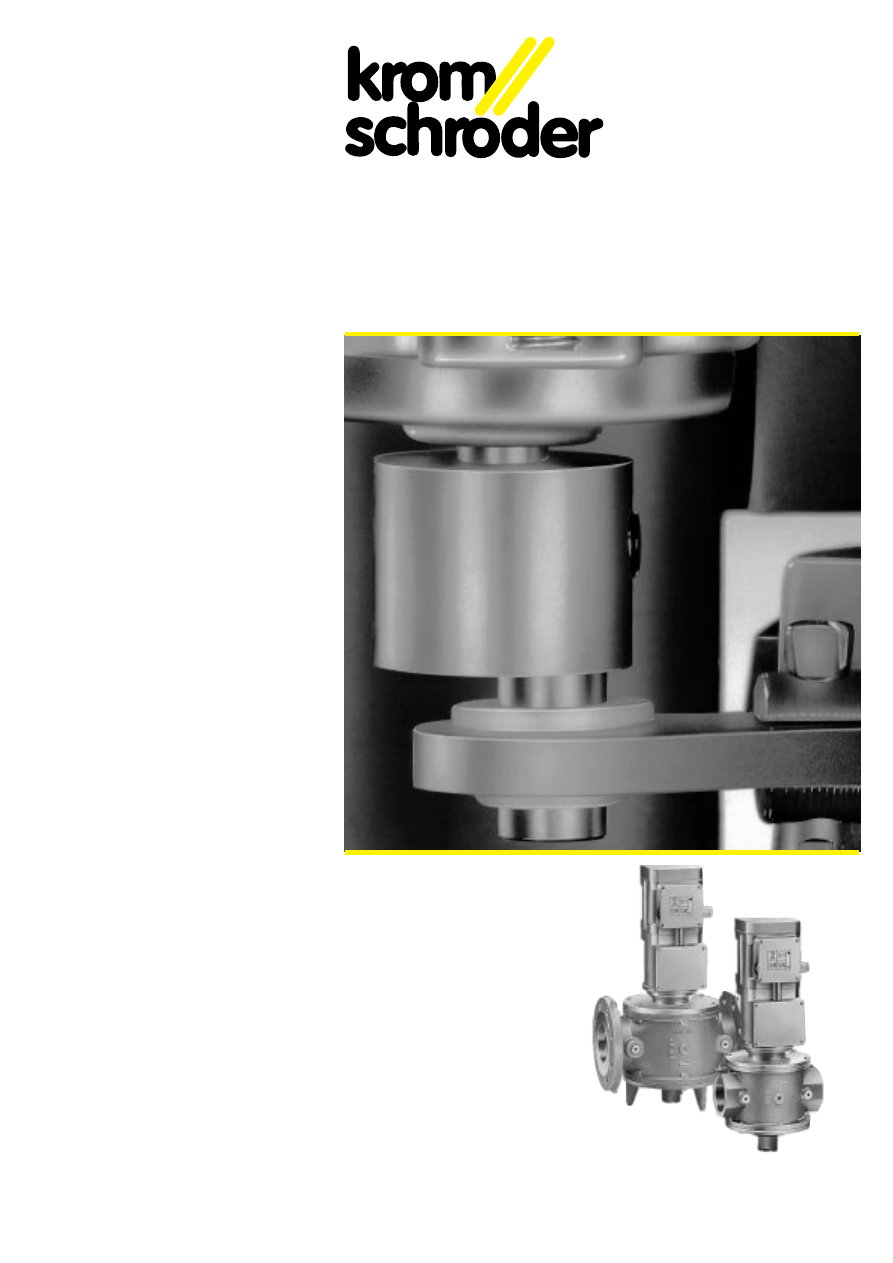
Function
Motorised valve VK is an hydraulically
actuated safety valve, normally (when de-
energised) closed.
When the mains voltage is applied, the
internal pump builds up an oil pressure.
This pressure slowly forces the valve disc
downwards by means of a piston. The
pump switches off when the valve is fully
open. As soon as the pressure drops,
repumping occurs briefly. When closing,
the voltage must be disconnected, the oil
pressure is then relieved and the closing
spring forces the valve disc to close within
1 second.
General technical data
Type of gas: town gas, natural gas, LPG
(gaseous) and air, also suitable for biolog-
ically produced methane and landfill gas.
With strainer made of VA steel for protect-
ing the valve seat and the valve disc seal.
Internal thread Rp to ISO 7-1
Flange PN 16 to ISO 7005
Closing time: 0.8 s
Opening time:
VK
VK..H
DN
1
40
5 s
–
DN
1
50-
1
65
8 s
12 s
DN
1
80-100
10 s
18 s
DN 125-200
13 s
24 s
DN 250
-
24 s
Ambient temperature:
see version
Storage and transport temperature:
-40
°
C to +60
°
C
Mains voltage: see version
Rating: see Table Specifications
ED duty cycle: 100 %
Connection: Pg 13.5
Protection class 1
Protective grade: IP 54 to IEC 529
The regulations of the local electricity util-
ity must also be observed.
Ventilgehäuse:
AlSi bei VK..A DN 40 bis DN 250 (Fig. 1+2),
GGG 40 bei VK..G DN 50 bis DN 200 (Fig. 3),
innen und außen mit Epoxid-Pulverlack
beschichtet
Die beiden Gehäuse sind mit den unter-
schiedlichen Oberteilen kombinierbar.
Max. Eingangsdruck: siehe Datentabelle
VK..G sind druckfest bis 8 bar und druck-
stoßfest bis 20 bar.
Ventiloberteil: AlSi
Ventiltellerdichtung:
Perbunan bis DN 150
Polyurethan DN 200
als Variante Viton DN 40 - 150
Normgerecht nach EN 161, Klasse A,
Gruppe 2.
Meß- oder Zündflammenanschluß Rp 1/4
beidseitig im Eingang und im Ausgang.
Mit Sieb aus VA-Stahl zum Schutz des
Ventilsitzes und der Ventiltellerdichtung
Funktion
Das Motorventil VK ist ein hydraulisch
betätigtes Sicherheitsventil, stromlos
geschlossen.
Nach Anlegen der Netzspannung baut die
interne Pumpe einen Öldruck auf. Dieser
drückt den Ventilteller über einen Kolben
langsam nach unten. Bei voller Öffnung
schaltet die Pumpe ab. Sobald der Druck
absinkt, wird kurz nachgepumpt. Zum
Schließen Spannung wegnehmen, der
Öldruck entspannt sich, und die Schließfe-
der drückt den Ventilteller innerhalb 1 s zu.
Allgemeine technische Daten
Gasart: Stadtgas, Erdgas, Flüssiggas
(gasförmig) und Luft, auch für Biogas und
Deponiegas geeignet
Innengewinde Rp nach ISO 7-1
Flansch PN 16 nach ISO 7005
Schließzeit: 0,8 s
Öffnungszeit:
VK
VK..H
DN 40
5 s
-
DN 50 - 65
8 s
12 s
DN 80 -100
10 s
18 s
DN 125 - 200
13 s
24 s
DN 250
-
24 s
Umgebungstemperatur:
siehe Ausführung
Lager- und Transporttemperatur:
-40
°
C bis +60
°
C
Netzspannung: siehe Ausführung
Leistungsaufnahme: siehe Datentabelle
Einschaltdauer ED: 100 %
Anschluß: Pg 13,5
Schutzklasse 1
Schutzart: IP 54 nach IEC 529
Zu beachten sind die Vorschriften der ört-
lichen Elektroversorgungsunternehmen.
Fonctionnement
La vanne motorisée VK est une vanne de
sécurité à commande hydraulique, fermée
en l'absence de courant.
Après branchement sur la tension du
réseau, la pompe intérieure établit une
pression d'huile. Cette pression repousse
lentement le clapet vers le bas au moyen
d'un piston. Lorsque la vanne est entière-
ment ouverte, la pompe s'arrête. Dès que
la pression tombe, la pompe se remet en
marche pour un temps bref. Pour fermer,
couper la tension, la pression d'huile
tombe et le ressort de fermeture referme le
clapet en moins de 1 s.
Caractéristiques techniques
générales
Types de gaz : gaz de ville, gaz naturel,
GPL (sous forme gazeuse) et air, convient
également pour le biogaz et le gaz de
décharge.
Corps de vanne :
AlSi pour VK..A, DN 40 à DN 250 (Fig. 1+2),
GGG 40 pour VK..G, DN 50 à DN 200
(Fig. 3), revêtu intérieur et extérieur de pein-
ture époxy par immersion dans la poudre
Les deux boîtiers peuvent être combinés
aux différents boîtiers supérieurs.
Pression d'entrée maxi: voir tableau
Les vannes VK..G résistent à la pression
jusqu'à 8 bars et aux fluides sous pres-
sion jusqu'à 20 bars.
Boîtier supérieur : AlSi
Joint de clapet :
Perbunan jusqu'à DN 150
Polyuréthane pour DN 200
en variante : Viton pour DN 40-150
Conforme à la norme EN 161, classe A,
groupe 2
Raccord de mesure ou de flamme d'allu-
mage Rp 1/4 des deux côtés, à l'entrée
et à la sortie
Filtre en acier VA pour la protection du
siège de vanne et du joint du clapet de
vanne.
Filetage intérieur Rp selon ISO 7-1
Bride PN 16 selon ISO 7005
Temps de fermeture: 0,8 s
Temps
d'ouverture
VK
VK..H
DN
1
40
5 s
-
DN
1
50-
1
65
8 s
12 s
DN
1
80-100
10 s
18 s
DN 125-200
13 s
24 s
DN 250
-
24 s
Température ambiante : selon le modèle
Température de stockage et de transport :
-40
°
C à +60
°
C
Tension du réseau: selon le modèle
Consommation de puissance: voir tableau
Durée d'enclenchement ED: 100%
Raccordement : Pg 13,5
Classe de protection 1
Type de protection : IP 54 selon IEC 529
Respecter les prescriptions des compag-
nies d'électricité locales
4
(G)
A = Com.
B = NO
C = NC
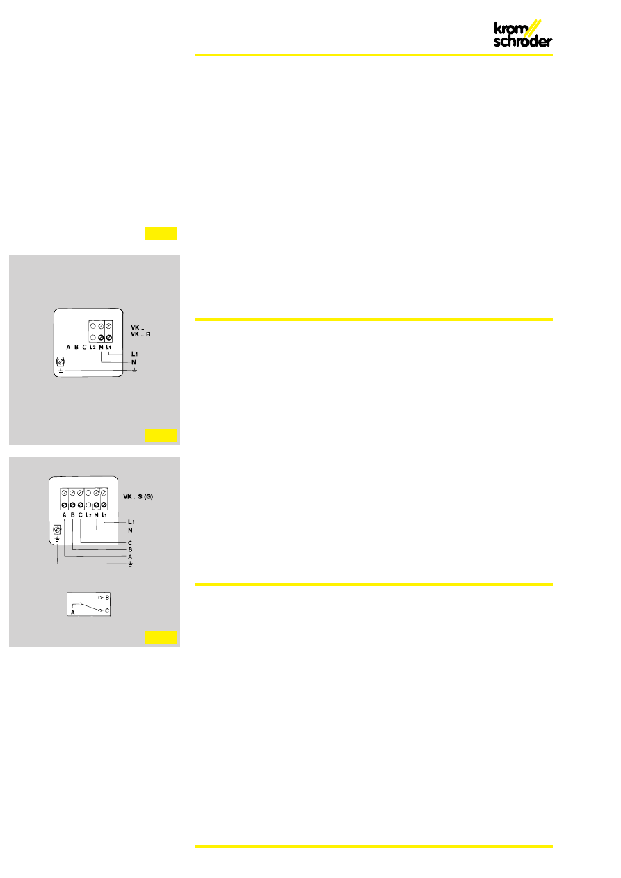
VK.., VK..H
VK..: Oberteil einstufig, langsam öffnend
VK..H: Oberteil mit verstärkter Antriebs-
kraft für höhere Eingangsdrücke, langsam
öffnend
VK.., VK..H:
Öffnungscharakteristik siehe (Fig. 9)
Elektrischer Anschluß siehe (Fig. 6)
Folgende Varianten sind lieferbar:
– mit Volumenstromdrossel (Standard),
– mit Meldeschalter (Option),
– mit Halterelais für die Wiederinbetrieb-
nahme von Hand (Option)
– mit Normgerätestecker nach
DIN 43650 (Option)
– mit 24 V= Haltespannung, VK..T5/K
(Option) (Fig. 7)
VK..Z
Oberteil zweistufig, langsam öffnend
Elektrischer Anschluß siehe (Fig. 8)
Folgende Varianten sind lieferbar:
- Mit Volumenstromdrossel (Standard):
Die 1. Stufe ist mit Hilfe eines Schalters
einstellbar zwischen 0 % und 90 % der
maximalen Leistung. Einstellung der 2.
Stufe mittels Volumenstromdrossel von
unten zwischen 0 % und 100 %.
Werksseitige Einstellung: maximaler
Volumenstrom.
– mit Meldeschalter (Standard)
VK.., VK..H, VK..Z
Technische Daten
Netzspannung:
220/240 V~ +10/-15% 50 Hz (Standard)
220 V~
+10/-15% 60 Hz
200 V~
+10/-10% 50/60 Hz
120 V~
+10/-15% 60 Hz
110 V~
+10/-15% 50/60 Hz
100 V~
+10/- 5% 50/60 Hz
Umgebungstemperatur: -15 bis +60
°
C
Einbau
in waagerecht oder senkrecht führende
Leitung (Fig. 11)
VK.., VK..H
VK..: upper section for one-step operati-
on, slow opening
VK..H: upper section with increased
actuating force for higher inlet pressures,
slow opening
VK.., VK..H:
Opening characteristics see (Fig. 9)
Electrical connection see (Fig. 6)
The following variants are available:
– with flow rate restrictor (standard)
– with position indicator (option)
– with holding relay for manual reset
(option)
– with standard plug to DIN 43650
(option).
– with 24 VDC with stand voltage,
VK..T5/K (option) (Fig. 7)
VK..Z
Upper section for two-step operation, slow
opening
Electrical connection see (Fig. 8)
The following variants are available:
- with flow rate restrictor (standard):
The 1st step can be set using a switch
between 0 % and 90 % of the maximum
flow. The 2nd step is set with a flow rate
restrictor from below between 0 % and
100 %.
Setting ex works: maximum flow rate.
– with position indicator (standard).
VK.., VK..H, VK..Z
Technical data
Mains voltage:
220/240 V AC
+10/-15% 50 Hz
(standard)
220 V AC
+10/-15% 60 Hz
200 V AC
+10/-10% 50/60 Hz
120 V AC
+10/-15% 60 Hz
110 V AC
+10/-15% 50/60 Hz
100 V AC
+10/- 5% 50/60 Hz
Ambient temperature: -15 to +60
°
C
Installation
in horizontal or vertical pipework (Fig. 11)
VK.., VK..H
VK..:
boîtier supérieur 1 étage, ouverture
lente
VK..H:
boîtier supérieur avec force d'en-
traînement renforcée pour grandes pres-
sions d'entrée, ouverture lente
VK.., VK..H:
caractéristique d'ouverture, voir (Fig. 9)
Raccordement électrique, voir (Fig. 6)
Nous pouvons fournir les variantes suivan-
tes:
– avec étranglement de débit (de série)
– avec indicateur de position (option)
– avec relais à maintien pour remise en
marche manuelle (option)
– avec fiche de branchement normalisée
selon DIN 43650 (option)
– avec tension de maintien 24 V =,
VK..T5/K (option) (Fig. 7)
VK..Z
Boîtier supérieur à deux étages, ouverture
lente. Raccordement électrique, voir (Fig. 8)
Nous pouvons livrer les variantes suivantes:
– avec étranglement de débit (de série):
le premier étage peut être réglé entre 0%
et 90% de la puissance maximum à l'ai-
de d'un commutateur. Réglage du deu-
xième étage à l'aide de l'étranglement
de débit, de bas en haut, entre 0% et
100%
Réglage d'usine: débit maximum
– Avec indicateur de position (de série)
VK.., VK..H, VK..Z
Caractéristiques techniques
Tension du réseau:
220/240 V~ +10/-15% 50 Hz (de série)
220 V~
+10/-15% 60 Hz
200 V~
+10/-10% 50/60 Hz
120 V~
+10/-15% 60 Hz
110 V~
+10/-15% 50/60 Hz
100 V~
+10/- 5% 50/60 Hz
Température ambiante: -15 à +60
°
C
Position de montage
Sur conduite horizontale ou verticale
(Fig. 11)
Fig. 4
Fig. 5
Fig. 6
Fig. 8
L
1
N
24 V=
VK..T5/K
L1
N
+
–
24 V=
NOT AUS
EMERGENCY STOP
ARRÊT D'URGENCE
Fig. 7
5
L
1
N
1
2
VK..X
L1
N
0
➔
1
VK..X
explosionsgeschütztes Oberteil für einstufi-
gen Betrieb, langsam öffnend
Öffnungscharakteristik siehe (Fig. 9)
Technische Daten
Netzspannung:
230 V +10/-15%, 50 Hz
230 V +10/-15%, 60 Hz
110 V +10/-15%, 50/60 Hz
Umgebungstemperatur:
-15
°
C bis +40
°
C
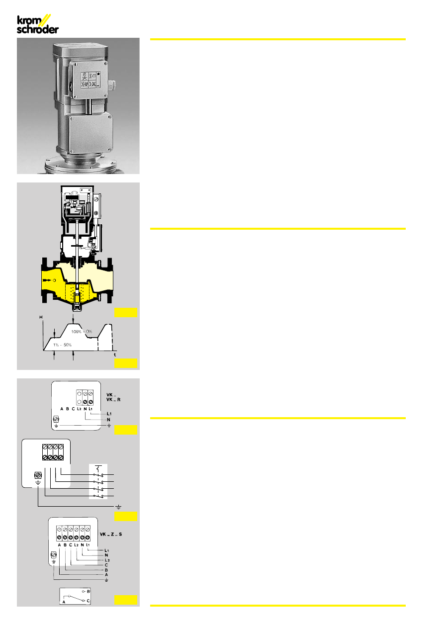
Verdrahtung
Die extern vorzusehende elektrische Ver-
drahtung (Fig. 10) ist zwingend vor-
geschrieben, der Betrieb ohne externe
Verdrahtung ist nicht zulässig. Erdungs-
anschluß/Potentialausgleich ist zusätzlich
außen am Gerät anzubringen, dabei darf
das Erdanschlußkabel nicht aus dem
Anschlußkasten nach außen verlegt wer-
den.
Die Anschlußkabel zum Anschlußkasten
VK..X müssen fest verlegt werden. Bei der
Errichtung elektrischer Anlagen in explo-
sionsgefährdeten Bereichen dürfen nur
bauartzugelassene elektrische Betriebs-
mittel eingesetzt werden.
Das Oberteil VK..X ist mit einer Mikrotem-
peratursicherung gegen erhöhte Öltempe-
ratur ausgerüstet. Bei Öltemperatur über
93
°
C wird das Ventil spannungsfrei ge-
schaltet, schließt automatisch und läßt sich
nicht mehr in Betrieb nehmen. Das Ober-
teil zur Überprüfung an den Hersteller
schicken.
Das VK..X hat keinen Meldeschalter.
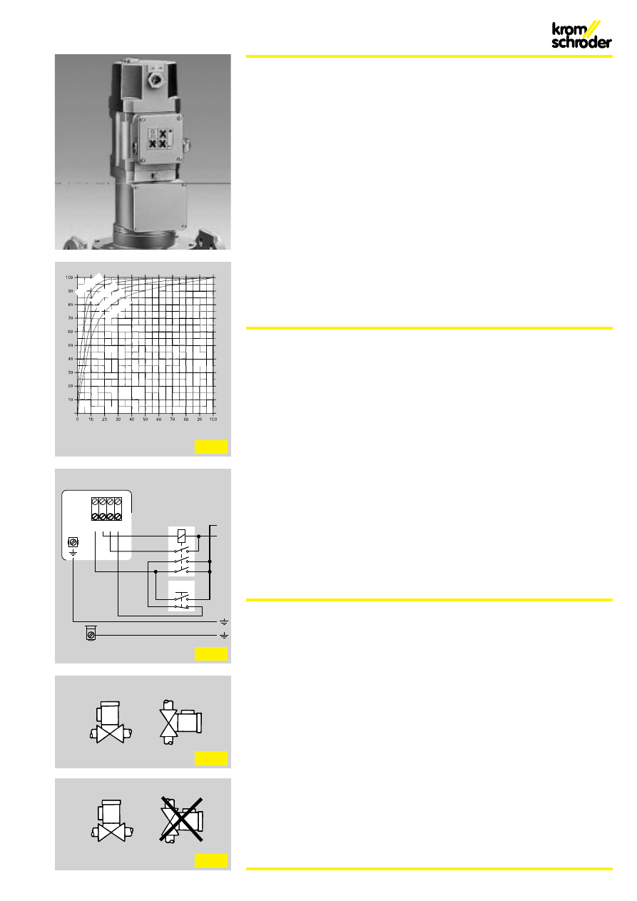
Einbau
nur in waagerecht führende Leitung, Ober-
teil nach oben zeigend (Fig. 12)
VK..X
Explosion-proof upper section for one-
step operation, slow opening
Opening characteristics see (Fig. 9)
Technical data
Mains voltage:
230 V +10/-15%, 50 Hz
230 V +10/-15%, 60 Hz
110 V +10/-15%, 50/60 Hz
Ambient temperature:
-15
°
C to +40
°
C
Wiring
External wiring (Fig. 10) is mandatory. Oper-
ation without external wiring is prohibited.
Earthing connection/equipotential bonding
is also to be fitted externally. The earthing
cable may not be wired outwards from the
connection box.
The connection cables to the VK..X
connection box must be fixed. When set-
ting up electrical appliances in hazardous
areas only type tested electrical equipment
may be used.
The VK..X upper section is equipped with
a miniature thermal cut-out for excessively
high oil temperatures. At an oil temperature
over 93
°
C the valve is de-energised, clo-
ses automatically and cannot be operated
any more. The upper section must be
returned to the manufacturer for checking.
The VK..X does not feature a position indi-
cator.
Installation
only in horizontal pipework, upper section
facing upwards (Fig. 12)
VK..X
Boîtier supérieur anti-déflagrant pour fonc-
tionnement à un étage, ouverture lente
Caractéristique d'ouverture, voir (Fig. 9)
Caractéristiques techniques
Tension du réseau:
230 V +10/-15%, 50 Hz
230 V +10/-15%, 60 Hz
110 V +10/-15%, 50/60 Hz
Température ambiante:
-15
°
C à +40
°
C
Câblage
Le câblage électrique à prévoir à l'extérieur
(Fig. 10) est strictement obligatoire. Le fonc-
tionnement sans câblage extérieur n'est
pas admis. Il faut monter en supplément
extérieurement sur l'appareil un raccorde-
ment de mise à la terre et une compensa-
tion de potentiel. Le câble de raccorde-
ment à la terre ne doit pas émerger à l'ex-
térieur de la boîte de raccordement.
Les câbles de raccordement aboutissant à
la boîte de raccordement de la VK..X doi-
vent être posés sur points fixes. Pour les
installations électriques montées dans des
régions sujettes à explosion, il ne faut utili-
ser que des moyens électriques du type de
construction autorisé.
Le boîtier supérieur VK..X est équipé d'une
micro-protection de température protége-
ant contre une élévation de la température
de l'huile. A une température d'huile de
plus de 93
°
C, la vanne est mise hors ten-
sion, elle se ferme automatiquement et ne
peut plus être remise en marche. Renvoy-
er le boîtier supérieur au constructeur pour
vérification.
Le VK..X via pas d’indicateur de position.
Position de montage
Uniquement sur conduite horizontale,
boîtier supérieur dirigé vers le haut (Fig. 12)
Fig. 10
Fig. 11
Fig. 12
Fig. 9
i
p = 10 m
bar
i
p = 10 m
bar
i
p = 50 m
bar
i
p = 100 m
bar
Öffnungszeit/Opening time/Temps d’ouverture t
ö
(%)
Dur
chfluß/Flow rate/Débit
V
l
(%)
6
Ausführungsbezeichnung VK..X entsprechend den europäischen Normen
EN 50014-1977 + A1-A5 (VDE 0170/0171 Teil 2/9.80) Allgemeine Bestimmungen
EN 50019-1977 + A1-A3 (VDE 0170/0171 Teil 6/1.87) Erhöhte Sicherheit „e“
EN 50015-1977 + A1 (VDE 0170/0171 Teil 1/1.87) Ölkapselung „o“
Zulassungs-Nr.: BVS: 91. C. 2045. ASEV: 92. 1C 10276
VK..X symbols pursuant to European standards
EN 50014-1977 + A1-A5 (VDE 0170/0171 part 2/9.80) General provisions
EN 50019-1977 + A1-A3 (VDE 0170/0171 part 6/1.87) Increased safety „e“
EN 50015-1977 + A1 (VDE 0170/0171 part 1/1.87) Oil encapsulation „o“
Approval no.: BVS: 91. C. 2045. ASEV: 92. 1C 10276
Désignation des modèles VK..X conformément aux normes europénnes
EN 50014-1977 + A1-A5 (VDE 0170/0171 parte 2/9.80) Spécifications générales
EN 50019-1977 + A1-A3 (VDE 0170/0171 parte 6/1.87) Sécurité renforcée „e“
EN 50015-1977 + A1 (VDE 0170/0171 parte 1/1.87) à bain d’huile „o“
Numéro d’homologation: BVS: 91. C. 2045. ASEV: 92. 1C 10276
Kennzeichen für elektrische Betriebsmittel
mit Bescheinigung einer EG-Prüfstelle
Symbol for electrical equipment with certification
from an EC test centre
Marque distinctive pour appareillages électriques
avec certificat d’un centre de contrôle CE
Symbol für elektrische Betriebsmittel, die nach
europäischen Normen gebaut sind
Symbol for electrical equipment built according
to European standards
Symbole pour appareillages électriques
qui sont construits aux normes européennes
EEx
Angewendete Zündschutzart
Type of ignition protection
Protection „e“ utilisée
e = erhöhte Sicherheit
o = Ölkapselung
e = increased safety
o = oil encapsulation
e = sécurité renforcée
o = à bain huile
eo
Einsatzbereich/Applications/domaine d’utilisation
II = elektrische Betriebsmittel für alle explosionsgefährdeten
Bereiche, außer schlagwettergefährdete Grubenbereiche
II = electrical equipment for all hazardous areas except for mines
susceptible to firedamp
II = appareillages électriques pour toutes les zones à risque
d’explosion sauf les quartiers grisouteux dans les mines
II
T 5 = > 100
°
C Zündtemperatur,
100
°
C höchste Oberflächentemperatur
T 5 = > 100
°
C ignition temperature,
100
°
C max. surface temperature
T 5 = > 100
°
C température d’inflammation,
température maximum de surface 100
°
C
T 5
7
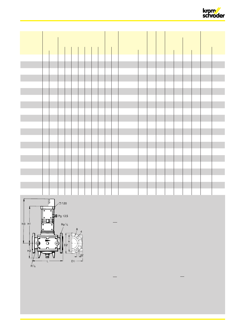
Datentabelle / Table specifications / Table de données
Typ
Baumaße / Dimensions
Bohrung
pmax mbar
V
l
Kv*
P 220 V
p
Gewicht
Type
Anschluß
Flansch / flange / bride
drilling
Kl. A
ip =
beim Öffnen
geöffnet
Weight
Connection
trous
Cl. A
1 mbar
when opening
when open
Poids
Raccord
Luft
à l’ouverture
ouvert
**
L
H1
H2
H3
D1
D2
k
d2
Anz.
Air
Al
DN
Rp
mm
mm
mm
mm
mm
mm
mm
mm
ALSi
GGG
m
3
/h
VA
W
VA
W
kg
VK
1
40..
–
Rp 1
1
⁄
2
150 345 100 430 127
–
–
–
–
1000 / 4000
–
27,5
31,3
90
50
9
9
1
8
VK
1
40..
1
40
–
200 345 100 430 127 150 110
18
1
4
1000 / 4000
–
27,5
31,3
90
50
9
9
1
9
VK
1
50..
–
Rp 2
180 350 117 435 155
–
–
–
–
1000 / 4000
–
45,0
51,2
90
50
9
9
1
9
VK
1
50..
1
50
–
230 350 117 435 155 165 125
18
1
4
1000 / 4000
4000
45,0
51,2
90
50
9
9
11
VK
1
50..H
1
50
–
230 414 117
–
155 165 125
18
1
4
–
8000
45,0
51,2
90
50
9
9
–
VK
1
65..
–
Rp 2
1
⁄
2
218 370 135 455 182
–
–
–
–
1000 / 3100
–
70,0
79,6
90
50
9
9
11
VK
1
65..
1
65
–
290 370 135 455 182 185 145
18
1
4
1000 / 3100
3100
70,0
79,6
90
50
9
9
13
VK
1
65..H
1
65
–
290 434 135
–
182 185 145
18
1
4
–
8000
70,0
79,6
90
50
9
9
–
VK
1
80..
1
80
–
310 378 137 463 210 200 160
18
1
8
1000 / 2400
2400
103,0 117,1
90
50
9
9
15
VK
1
80..H
1
80
–
310 442 137
–
210 200 160
18
1
8
–
6000
103,0 117,1
90
50
9
9
–
VK 100..
100
–
350 400 163 485 248 229 180
18
1
8
1000
1000
148,0 168,3
90
50
9
9
19
VK 100..H
100
–
350 464 163
–
248 220 180
18
1
8
–
4000
148,0 168,3
90
50
9
9
–
VK 125..
125
–
400 450 158 535 314 250 210
18
1
8
600
600
206,0 234,2
90
50
9
9
24
VK 125..H
125
–
400 514 158
–
314 250 210
18
1
8
1000
2000
206,0 234,2
90
50
9
9
25
VK 150..
150
–
480 445 173 530 344 285 240
23
1
8
400
400
310,0 352,5
90
50
9
9
32
VK 150..H
150
–
480 509 173
–
344 285 240
23
1
8
1000
1500
310,0 352,5
90
50
9
9
33
VK 150/100..H
150
–
480 509 173
–
344 285 240
23
1
8
–
4000
148,0 168,3
90
50
9
9
–
VK 200..
200
–
600 475 218 560 420 340 295
23
12
230
230
490,0 557,2
90
50
9
9
52
VK 200..H
200
–
600 539 218
–
420 340 295
23
12
1000
1000
490,0 557,2
90
50
9
9
53
VK 200/100..H
200
–
600 539 218
–
420 340 295
23
12
–
4000
148,0 557,2
90
50
9
9
–
VK 250..H
250
–
730 573 270
–
496 405 355
27
12
500
–
590,0 670,0
90
50
9
9
80
GGG
kg
–
–
–
20,5
21
–
26
27
32
33
41,5
43
60
61
80
81
81
141
142
142
–
** VK..X, + 1,5 kg
Flansch / Flange / Bride DIN 2501 C, PN 16
* Druckverlust und Durchfluß der Ventile
wird im allgemeinen aus den Durchfluß-
kurven entnommen.
*
Die Auswahl der Ventile kann aber auch
nach VDI/VDE 2173 durch die Kenn-
größe „Kv-Wert“ erfolgen (siehe Daten-
tabelle).
*
Kv = V x
ED
p
[m
3
/h]
* Kv = V x
ip
*
p [kg/m
3
];
ip [mbar]; V
l
[m
3
/h]
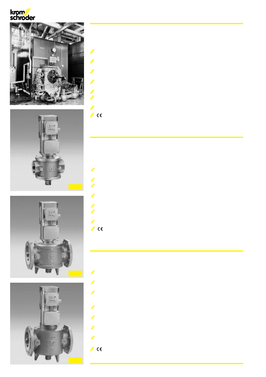
* Normally, pressure loss and flow rate
for valves are read from the flow rate
diagram.
*
However, the valves can also be chosen
in accordance with VDI/VDE 2173, by
determining the characteristic “KV
value” (see table specifications).
*
Kv = V x
ED
p
[m
3
/h]
* Kv = V x
ip
*
p [kg/m
3
];
ip [mbar]; V
l
[m
3
/h]
* Normalement, la perte de charge et le
débit des vannes peuvent être lus dans
le diagramme de débit.
*
Mais, les vannes peuvent aussi être choi-
sies selon VDI/VDE 2173, en détermi-
nant la characteristique “valeur-Kv” (voir
la table de données).
*
Kv = V x
ED
p
[m
3
/h]
* Kv = V x
ip
*
p [kg/m
3
];
ip [mbar]; V
l
[m
3
/h]
8
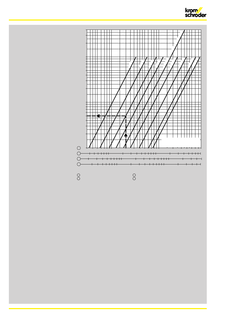
Druckverlust · Pressure drop · Perte de charge
∆
p [mbar]
2
3
4
5
6
8
10
20
30
40
50
60
80
30
40
50 60
80 100
200
300 400
1
40
50 60
80 100
200
300 400
2
30
40
50 60
80 100
200
300 400
4
20
30
40
50 60
80 100
200
300
3
600
V'
[m
3
/h (n)]
1
600 800 1000
800 1000
600 800 1000
400
600
2000
3000 4000
2000
3000 4000
2000
3000 4000
800 1000
2000
3000
6000
6000 8000
8000
6000
4000
100
200
300
400
= Erdgas / Natural gas / Gaz naturel / dv = 0,62
1
= Stadtgas / Town gas / Gaz de ville / dv = 0,45
2
= Flüssiggas / LPG / Gaz de pétrole liquéfié / dv = 1,56
3
= Luft / Air / dv = 1,00
4
VK 40
VK 50
VK 65
VK 80
VK 100
VK 150/100, VK 200/100
VK 125
VK 150
VK 200VK 250
Volumenstrom nach EN 161
Flow rate in acc. with EN 161
Diagramme de débit selon EN 161
Hinweis: Beim Einlesen von Betriebsku-
bikmetern (ohne Umrechnung in m
3
[n]) in
das Diagramm ist der abgelesene Druck-
verlust mit dem absoluten Druck in bar
(1 + Überdruck in bar) zu multiplizieren.
Note: When reading operating cubic met-
res in the diagram (without converting to
m
3
[n]), the pressure loss as read, is to be
multiplied with the absolute pressure in bar
(1 + positive pressure in bar).
Remarque: En lisant la valeur en mêtre
cube de service (sans conversion en m
3
[n]) sur le diagramme, multiplier la perte de
pression lue avec la pression absolue en
bar (1 + pression effective en bar).
Beispiel: Im Motorventil VK 65 sind
Volumenstrom
= 200 m
3
/h Erdgas
Gasdruck
= 1 bar
200 m
3
/h – VK 65 – 5 mbar
abgelesen im Diagramm
ip = 5 x (1 + 1) = 10 mbar
am Motorventil VK 65
Example: In the motorized valve VK 65
flow rate
= 200 m
3
/h natural gas
gas pressure
= 1 bar
200 m
3
/h – VK 65 – 5 mbar
read from the diagram
ip = 5 x (1 + 1) = 10 mbar
at the motorized valve VK 65
Exemple: Dans la vanne motorisée VK 65
débit
= 200 m
3
/h
de gaz naturel
pression de gaz = 1 bar
200 m
3
/h – VK 65 – 5 mbar
lu sur le diagramme
ip = 5 x (1 + 1) = 10 mbar
à la vanne motorisée VK 65
Volumenstrom-Diagramm
Volume flow diagram
Diagramme de débit volumique
9
A = Com.
B = NO
C = NC
Zubehör
Meldeschalter (Fig. 13) bei VK..S (G)
Diese Geräte sind mit einem Schalter für
die Meldung „geschlossen“ oder "nicht
geschlossen" oder als Stufenmelder ver-
wendbar.
Anschlußwerte: 30-250 V, 50/60 Hz, max.
10 A (ohmsche Last) bei VK..S.
Bei Spannung < 30 V Ausführung VK..G
mit vergoldeten Kontakten verwenden; I =
0,1 A (ohmsche Last).
Elektrischer Anschluß (Fig. 15)
Halterelais bei VK..R
Das Halterelais für die "Wiederinbetrieb-
nahme von Hand" verhindert, daß nach
einem Spannungsausfall das Gas automa-
tisch wieder freigegeben wird.
Elektrischer Anschluß (Fig. 14)
Accessories
Position indicator (Fig. 13) on VK..S (G)
These appliances can be used with a
switch for the indication "closed" or "not
closed" or as step indicators.
Connection ratings: 30-250 V, 50/60 Hz,
max. 10 A (resistive load) on VK..S.
If the voltage is < 30 V, please use version
VK..G with gold-plated contacts; I = 0.1 A
(resistive load).
Electrical connection (Fig. 15)
Holding relay on VK..R
The holding relay for manual restart stops
gas from being automatically released
again after a power cut.
Electrical connection (Fig. 14)
Accessoires
Indicateur de position (Fig. 13) pour
VK..S (G)
Ces appareils peuvent être utilisés avec un
commutateur pour la signalisation „fer-
mée“ ou „non fermée“ ou en qualité d'indi-
cateur d'étage.
Raccordements: 30 à 250 V, 50/60 Hz,
maxi 10 A (charge ohmique) pour VK..S
Pour les tensions < 30 V, utiliser le modèle
VK..G à contacts d'or; I = 0,1 A (charge
ohmique)
Raccordement électrique (Fig. 15)
Relais à maintien pour VK..R
Le relais à maintien pour „remise en mar-
che manuelle“ évite qu'après une panne
de courant, le gaz soit automatiquement
libéré.
Raccordement électrique (Fig. 14)
Fig. 13
Fig. 14
Fig. 15
R
P
P
P
–
–
–
–
–
F
P
P
P
P
P
P
P
P
02
–
–
–
–
–
–
–
P
04
–
–
–
–
–
–
P
–
06
–
–
–
–
–
P
–
–
10
P
P
P
P
P
–
–
–
24
–
–
–
p
–
–
–
–
31
–
–
p
–
–
–
–
–
40
p
p
–
–
–
–
–
–
Z**
p
p
p
p
p
p
p
p
T5
P
P
P
P
P
P
P
P
W5
p
p
p
p
p
p
p
p
W6
p
p
p
p
p
p
p
p
Y
p
p
p
p
p
p
p
p
Q6
p
p
p
p
p
p
p
p
M
p
p
p
p
p
p
p
p
P
p
p
p
p
p
p
p
p
A
P
P
P
P
P
P
P
P
G***
–
p
p
p
p
p
p
p
9
P
P
P
P
P
P
P
P
6
p
p
p
p
p
p
p
p
3
P
P
P
P
P
P
P
P
D
P
P
P
P
P
p
p
p
S**
p
p
p
p
p
p
p
p
G
p
p
p
p
p
p
p
p
S2
p
p
p
p
p
p
p
p
V
p
p
p
p
p
p
p
–
R**
p
p
p
p
p
p
p
p
F
p
p
p
p
p
p
p
p
T5/K
p
p
p
p
p
p
p
p
VK 40..
VK 50..
VK 65..
VK 80..
VK 100..
VK 125..
VK 150..
VK 200..
R
P
P
P
–
–
–
–
–
F
P
P
P
P
P
P
P
P
02
–
–
–
–
–
–
–
P
04
–
–
–
–
–
–
P
–
06
–
–
–
–
–
P
–
–
10
P
P
P
P
P
–
–
–
24
–
–
–
p
–
–
–
–
31
–
–
p
–
–
–
–
–
40
p
p
–
–
–
–
–
–
W5
P
P
P
P
P
P
P
P
W6
p
p
p
p
p
p
p
p
M
p
p
p
p
p
p
p
p
A
P
P
P
P
P
P
P
P
G***
–
p
p
p
p
p
p
p
9
P
P
P
P
P
P
P
P
3
P
P
P
P
P
P
P
P
D
P
P
P
P
P
p
p
p
V
p
p
p
p
p
p
p
–
F
p
p
p
p
p
p
p
p
VK 40..X
VK 50..X
VK 65..X
VK 80..X
VK 100..X
VK 125..X
VK 150..X
VK 200..X
F
P
P
P
P
P
P
P
P
P
P
10
–
–
–
–
P
P
–
P
–
–
05
–
–
–
–
–
–
–
–
–
P
15
–
–
–
–
–
P
–
–
–
–
20
–
–
–
–
P
–
–
–
–
–
40
–
–
–
P
–
–
P
–
P
–
60
–
–
P
–
–
–
–
–
–
–
80
P
P
–
–
–
–
–
–
–
–
T5
P
P
P
P
P
P
P
P
P
P
W5
p
p
p
p
p
p
p
p
p
p
W6
p
p
p
p
p
p
p
p
p
p
Y
p
p
p
p
p
p
p
p
p
p
Q6
p
p
p
p
p
p
p
p
p
p
M
p
p
p
p
p
p
p
p
p
p
P
p
p
p
p
p
p
p
p
p
p
A
–
–
–
–
p
p
–
p
–
P
G
P
P
P
P
P
P
P
P
P
–
9
P
P
P
P
P
P
P
P
P
P
6
p
p
p
p
p
p
p
p
p
p
3
P
P
P
P
P
P
P
P
P
P
D
P
P
P
P
p
p
p
p
p
p
S
p
p
p
p
p
p
p
p
p
p
G
p
p
p
p
p
p
p
p
p
p
S2
p
p
p
p
p
p
p
p
p
p
R
p
p
p
p
p
p
p
p
p
p
V
p
p
p
p
p
p
p
–
–
–
F
p
p
p
p
p
p
p
p
p
p
T5/K
p
p
p
p
p
p
p
p
p
p
VK 50..H
VK 65..H
VK 80..H
VK 100..H
VK 125..H
VK 150..H
VK 150/100..H
VK 200..H
VK 200/100..H
VK 250..H
*
VK.., VK..Z
VK..H
VK..X
*
10
Technische Änderungen, die dem Fortschritt dienen, vorbe-
halten.
We reserve the right to make technical changes designed to
improve our products without prior notice.
Toutes les caractéristiques sont sujettes à modifications sans
avis préalable.
*
In einigen EU-Ländern sind für Anschlüsse > DN 50 nur geflanschte Anschlüsse zulässig.
Only flanged connections are permitted in certain EC countries for connections > DN 50.
dans certains pays de l’UE, seuls les raccordements à brides sont admis pour les raccordements > DN 50
**
Das VK..Z ist immer mit Meldeschalter, aber nicht mit Halterelais lieferbar.
The VK..Z is always available with position indicator but not with holding relay.
la vanne VK..Z peut être livrée avec un indicateur de position mais non pas avec un relais à maintien
***
Beim VK..G gilt der höhere Eingangsdruck. Es ist nur mit Flanschanschluß lieferbar.
The higher inlet pressure applies on the VK..G. Available only with flange connection.
pour la vanne VK..G, c'est la plus haute pression d'entrée qui est valable. Cette vanne ne peut être livrée qu'avec
raccordement à brides
Auswahl
Selection
Choix
● Standard / de série
●
●
Option / option
- nicht lieferbar / unavailable / non disponible
Typenschlüssel VK 40-250
Type code VK 40-250
Code de type VK 40 à 250
03250022 7.99 F
.T 5000
Z* T5 X*
9
A
3 D*
R*
S*
V* F*
10
F
40
VK
Typ/type
Nennweite
Nominal size
Diamètre nominal
220/240 V~, 50Hz
= T5
230 V~, 50 Hz
= W5
230 V~, 60 Hz
= W6
200 V~, 50/60 Hz
= Y
120 V~, 60 Hz
= Q6
110 V~, 50/60 Hz
= M
100 V~, 50/60 Hz
= P
220 V~, 50 Hz/24 V= = T5/K
Rp-Gewinde
Rp-thread
Tauraudage Rp
40, 50, 65, 80, 100, 125, 150, 150/100
200, 200/100, 250
= R
Fansch
Flange
Bride
= F
Max. Eingangsdruck
Maximale inlet pressure
Pression dí entrèe max.
Zweistufig*
2-step*
À deux étages*
= Z*
Netzspannung
Mains voltage
Tension de secteur
Ventilgehäuse-Werkstoff
Valve housing material
Matière du boîtier de la vanne
ALSi = A
GGG 40 = G
Metall-Anschlußkasten mit Klemmen, IP 54
Metal connection box with terminals, IP 54
Boîtier de raccordement métalique avec bornes, IP 54
= 9
Mengeneinstellung*
Flow adjustment*
Ajestement de débit*
= D*
230 mbar = 02
400 mbar = 04
500 mbar = 05
600 mbar = 06
1000 mbar = 10
1500 mbar = 15
2000 mbar = 20
2400 mbar = 24
3100 mbar = 31
4000 mbar = 40
6000 mbar = 60
8000 mbar = 80
Explosionsgeschützte Ausführung*
Actuator in explosion-proof version*
Entraînement en modèle antidéflagrant*
= X*
= H*
Ausführung für höhere Eingangsdrücke*
Version for higher inlet pressure*
Version pour pressions de sortie supérieures*
Verschlußschraube im Eingang und Ausgang
Screw at the inlet and outlet
Vis à l'entrée et à la sortie
= 3
= 6
... mit Normsteckdose
... with standard socket
... prise standard
* Wenn "ohne" entfällt dieser Buchstabe d h der nächste rückt auf
2 Meldeschalter*
2 Position indicators*
2 Indication de position*
= S2*
Meldeschalter*
Position indicator*
Indication de position*
= S*
= G*
Halterelais*
Holding relay*
Relais à maintien*
= R*
Viton-Ventiltellerdichtung*
Viton-Valve disc seal*
Viton-Clapet*
= V*
Sichtfenster*
Viewing Window*
Cadran*
= F*
... mit Goldkontakten*
... with gold-pltd contacts*
... avec des contacts d'or*
Kr
omschröder pr
oduzier
t umweltfr
eundlich.
For
der
n Sie unser
en Umweltbericht an.
Kr
omschröder uses envir
onment-friendly pr
oduction methods.
Please send away for our Envir
onment Repor
t.
Chez Kr
omschröder
, la pr
oduction r
especte l’envir
onment.
Demandez notr
e rappor
t envir
onnemental.
* Wenn „ohne“ entfällt dieser Buchstabe, d.h. der nächste rückt auf.
* When ’’without’’, this letter is dropped, i.e. the next one moves up.
* Si ’’sans’’, cette lettre est sans object, c’est-à-dire que la suivante est appelée.
G. Kromschröder AG
Tel. 05 41/12 14-0 · Fax 05 41/1 21 43 70
Postfach 2809
www.kromschroeder.de
D-49018 Osnabrück
kromschroeder@t-online.de
Wyszukiwarka
Podobne podstrony:
Grupy krwi VK
Grupy krwi VK 2
Grupy krwi VK
BAT VK 75
table VK
VK PPSM Openers
VK PPSM Super Self Image for Seduction
VK 2 SPECIAL 80 EC
więcej podobnych podstron