
VAZ-21215-10 vehicle
The VAZ-21215-10 vehicle is fitted with the diesel engine
DHW (XUD-9SD).
The section gives a brief description of diagnostic procedures
for fuel and electrical systems, engine removal and refitting,
repair procedures for engine systems.
For detailed design, repair and diagnostic procedures with
respect to all engine systems using specialized tools and diag-
nostic charts, refer to PEUGEOT Repair Manual for Diesel
Engine.
The diesel engine operation depends much on the sound fuel
injection system, this is why this section focuses on the fuel sup-
ply units and components.
In the event the injection system has failed, do not blame the
high pressure pump, first check the following:
– fuel tank and fuel level;
– delivery and return fuel lines;
– fuel filter;
– injectors;
– glow plugs;
– engine stop solenoid resistance.
Examine the engine, since higher flash-point temperature
depends on compression, valve and piston ring condition.
Inspect the air cleaner, battery, starter motor, check the oil
level.
Major faults and remedial actions
1. Engine does not start, emitting no smoke:
- check fuel level in fuel tank;
- set engine manual stop device to normal position;
- check fuel delivery pipes; in case of leaks, tighten connections or
replace pipes;
- check engine stop solenoid for resistance, wiring conductivity and fuel
inflow.
If engine still fails to start after all these checks and remedial actions,
remove high pressure pump and test it using specialized equipment.
2. Engine does not start, emitting black smoke:
- when engine speed is below 150 rpm, check condition and fitting of bat-
tery terminals and starter motor, battery charge, oil grade and oil level;
- when engine speed is over 150 rpm, start engine without using air
cleaner; when no smoke is evident, renew filter element, check proper
mounting of air cleaner housing;
- check injection timing is correct, check fuel injectors are sound;
- check valve adjustment and compression in cylinders.
Should smoke persists despite all remedial actions, remove and test
pump using specialized equipment.
3. Engine does not start, emitting white smoke (cold engine):
Check the following items:
- glow plugs;
- secondary warming-up system;
- cylinder head gasket;
- injection timing.
If smoke persists after repair work, remove pump for inspection.
4. Difficult cold engine start with black smoke:
Check the following items:
- glow plugs;
- fast idle thermostat;
- injection timing;
- injectors;
- hydraulic lifters and valve clearances;
- compression.
Should smoke persists after repair, remove and test pump using spe-
cialist equipment.
5. Engine starts and stalls:
Check the following items:
- idle adjustment;
- oil grade and oil level;
- ventilation system;
- fuel feed system;
- solenoid;
- secondary warming-up system;
- air cleaner;
- non-return valve on LUCAS pump.
Should engine stalls despite repair performed, remove fuel pump.
6. Unstable idle:
Check the following items:
- settings of engine stop prevention system and idle (for LUCAS);
- settings for idle and fuel remainder return (for BOSCH);
- accelerator lever spring;
- fuel feed system;
- injectors;
- valve clearances;
- cam belt tension.
In case of failure to adjust idle speed, remove and examine pump on
a specialist test bench.
Engine - removal and refitting
Place the vehicle on the lift or over an inspection pit, chock
the front wheels and raise the rear axle from one or both sides.
Withdraw the bonnet, disconnect wiring from the battery and
electrical units fitted to the vehicle. Remove the battery and
underbonnet lamp.
Drain fluid form the cooling system and heater; to do this
unplug the expansion tank, undo the drain plugs on the radiator
(underneath, left-hand side) and on the cylinder block (left-hand
side).
198
From the engine (Fig.9-17) disconnect the coolant supply
and return hoses, remove the radiator complete with the grille
and fan cowl. Disconnect the cooling hoses from the thermostat.
Disconnect the hoses between the engine and heater.
From the air cleaner (Fig.9-18) disconnect the crankcase
vent hose, undo three securing nuts, remove the air cleaner
cover complete with the gasket; extract the filter element. Undo
four nuts which hold the air cleaner housing to the intake pipe
and withdraw the air cleaner housing and gasket.
Disconnect the fuel delivery and return hoses from the high
pressure fuel pump.
Using a box spanner, undo the nuts retaining the front
exhaust pipe to the exhaust manifold.
Using a flat screwdriver, release the ball end and disconnect
the fuel delivery operating cable from the high pressure pump.
Undo the retaining screw and release the end piece, then dis-
connect the cable from the timing advance lever.
Remove the transmission, working as described in section
«Gearbox» in the Repair Manual.
Hoist the cross-piece íëé-3/379 and lock the engine on the
right-hand side at the clamp, fitted to the front exhaust manifold
securing stud, while on the left-hand side - at the hole for clutch
housing fastening. Slightly tighten the hoist chain, undo the nuts
securing engine mounting rubbers 2 (Fig.9-19) to the front sus-
pension cross-member and lift the engine out.
Remove the heat shield of the starter motor and withdraw the
starter motor. Undo the clutch retaining bolts and withdraw the
clutch.
Refitting the engine is carried out as follows:
- refit the cooling hoses, connectors and clamps;
- check the radiator for deposits, leaks, damages;
- check the radiator cooling fan operation;
- check the radiator cap seal and valve;
- fit a new air cleaner and fuel filter elements;
- refill the engine with oil;
- adjust the controls;
- eliminate air pockets and refill the cooling system;
- start and warm-up the engine;
- adjust idle speed;
- check the lubricating and cooling systems for leaks.
Draw special attention to the engine / transmission connec-
tion: the input shaft must fully engage the splines of the clutch
disc.
199
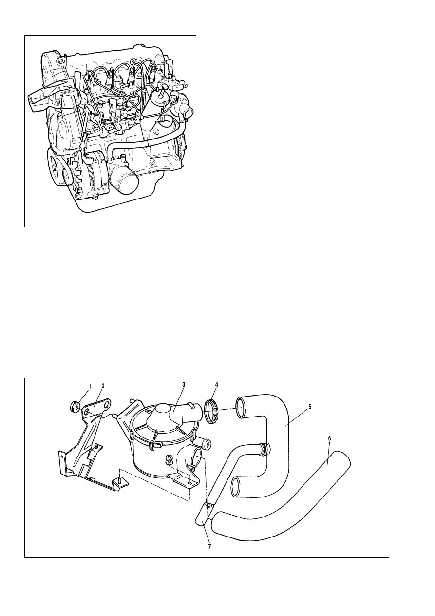
Fig.9-17. Engine - general view
Fig.9-18. Air cleaner:
1 - mounting rubber; 2 - bracket; 3 - air cleaner; 4 - clasp; 5 - air duct; 6 - cold air intake; 7 - crankcase emission hose
Cooling system
Design description
The cooling system is of closed-, pressurized type, with
expansion tank (Fig.9-20).
The coolant pump is of centrifugal type, driven by a V-belt
from the crankshaft pulley.
The cooling system includes radiator 7 with expansion tank 5,
thermostat 13, coolant temperature gauge, water jacket and con-
necting hoses.
During engine operation, water, warmed up in the water jack-
et, through the drain pipe flows to the radiator or thermostat,
depending on the thermostat valve position. Then water is sucked
by the pump and returned to the water jacket.
The cooling system is fitted with a built-in double-acting ther-
mostat, the valve opening temperature is 83°ë.
Coolant - level and density check
With the cold engine (15-20°ë) the level of water in the
expansion tank must be 25-30 mm above the «MIN» mark.
WARNING. It is recommended to check the water level on
the cold engine, since on heating up water expands, so the
fluid level can rise significantly on the warm engine.
When necessary, use areometer to check the coolant densi-
ty to be 1.078-1.085 g/cm
3
for íÓsÓl Ä-40.
When the level in the expansion tank is below the norm, while
the density exceeds the value required, add distilled water. In
case of normal density top up the coolant of the same grade as
the coolant in the cooling system.
Coolant change
Observe the following procedure when changing coolant:
- set the heater controls in the position «heating»;
- undo the caps in the bottom radiator cooler and cylinder
block, remove the expansion tank cap and drain coolant through
two drain holes. Detach the expansion tank and lift it over the
radiator, then remove the coolant remainder from the expansion
tank;
- to flush the cooling system, fill the system with clean water,
start the engine and run it until the radiator bottom cooler is warm.
With engine idling, drain water through the drain holes, stop the
engine and let it cool;
- repeat flushing steps as described above;
- after flushing refit the caps and fill the system with new
coolant 25-30 mm above the «MIN» mark on the expansion tank;
Fill coolant through the filler neck of the expansion tank. Refit
the cap, start the engine and allow it to idle for 1.5-2 minutes.
Stop the engine and when necessary top up coolant.
Cambelt - removal and refitting
The cam removal procedure is as follows (Fig.9-21):
- remove covers 3, 5 Ë 6 of valve timing mechanism;
- fix the flywheel using tool OUT0000049;
- loosen the crankshaft pulley retaining bolts;
- remove the crankshaft pulley;
- fix the flywheel with tool OUT0000015;
- secure the camshaft and fuel pump pulleys with retaining
bolts (the bolts should be hand tightened only);
- loosen nut 2 and bolt 4 (Fig.9-22);
200
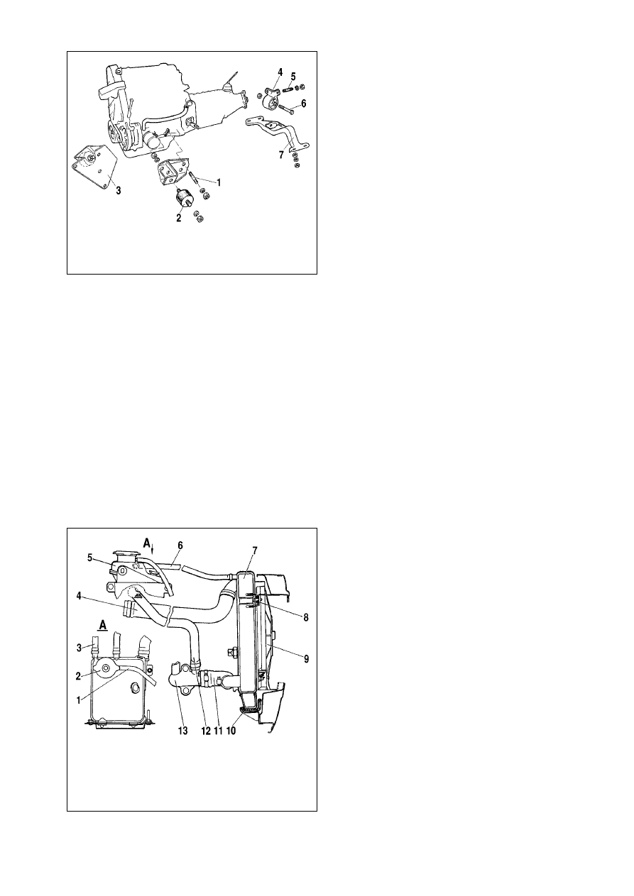
Fig.9-20. Cooling system:
1 - expansion tank vapour discharge pipe; 2 - expansion tank cap; 3 - engine
vapour discharge hose; 4 - radiator delivery hose; 5 - expansion tank; 6 - radi-
ator vapour discharge pipe; 7 - radiator; 8 - top radiator mounting rubber; 9 -
electric fan blower; 10 - bottom mounting rubber; 11 - return hose; 12 - filler
hose; 13 - thermostat
Fig.9-19. Engine support:
1 - left-hand bracket retaining pin; 2 - engine mounting rubber; 3 - right-hand
bracket /rubber assembly; 4 - bracket with rear engine support mounting; 5 - pin;
6 - bolt; 7 - rear engine support cross-piece
- use special wrench (of 10 mm square size) for 5 mm square
hole and turn the bracket clockwise to remove spring 6;
- tighten bolt 4;
- remove the cambelt.
Refitting is the reversal of the removal procedure:
- make sure the camshaft and fuel pump pulleys are in the
position required and secured, idler pulley 7 (Fig.9-22) and ten-
sioner 3 rotate freely, while plunger 1 and spring 6 are free with-
in the tensioner housing;
- refit the belt providing it is taut;
- refit the timing belt over the pulleys in the following order:
crankshaft pulley, idler pulley 7, fuel pump pulley, camshaft pul-
ley, tensioner pulley, water pump;
- slacken bolt 4 to release the tensioner;
- remove the retaining bolts and flywheel retainer;
- tighten bolt 4 and nut 2;
- rotate the crankshaft two turns clockwise.
Tension - checking:
- tighten the retaining bolts and refit the flywheel retainer;
- loosen bolt 4 and nut 2 to spread tension over the belt;
- tighten bolt 4 and nut 2 to 18 N•m;
- refit the crankshaft pulley;
- coat bolt 20 with Loctite 243;
- fix the flywheel with tool OUT0000049;
- refit the pulley retaining bolt, torque to 40 N•m, turn to fur-
ther 60°;
- refit bottom cover 3 (Fig.9-21), tighten bolts 1 to 15 N•m;
- refit cover 5, tighten bolts 4 to 15 N•m;
- tighten right-hand cover 6 bolt 7 to 10 N•m.
Note. When you fail to refit any securing bolt or a retainer,
repeat the complete procedure for the cambelt refitting.
Alternator - removal and refitting
Removal. Loosen tensioner 2 bolt and bolt 9 (Fig.9-23).
Tighten bolt 8 until it comes against the limiter. Remove the belt.
CHECK to see pulley 4 rotates easily without seizures.
201
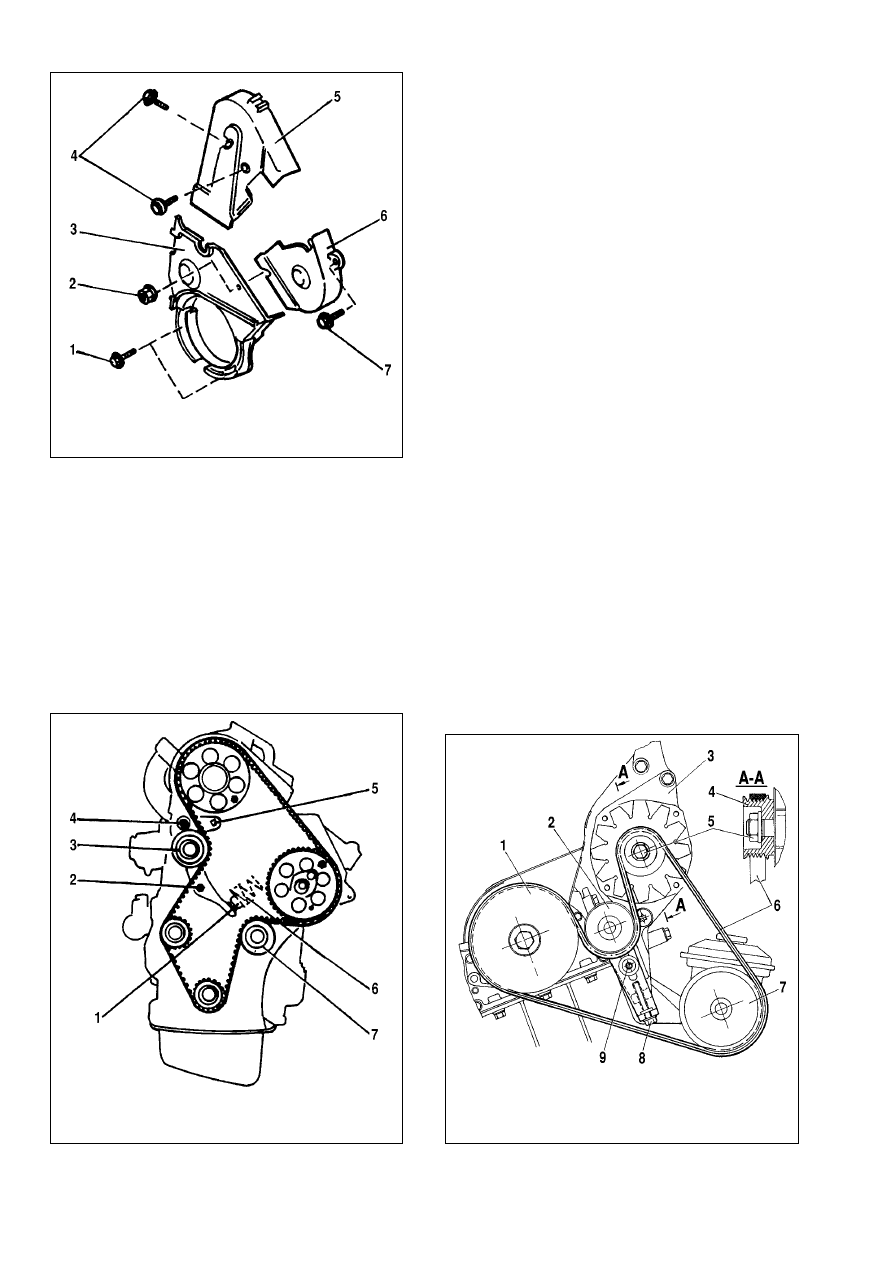
Fig.9-21. Removing and refitting the timing covers:
1 - securing bolts, bottom cover; 2 - nut; 3 - bottom cover; 4 - securing bolts,
left-hand cover; 5 - left-hand cover; 6 - right-hand cover; 7 - bolt
Fig.9-22. Removing and refitting the cambelt:
1 - plunger; 2 - nut; 3 - tensioner roller; 4 - bolt; 5 - square-type hole; 6 - spring;
7 - idler pulley
Fig.9-23. Removing and refitting the alternator drive belt:
1 - crankshaft pulley; 2 - tensioner pulley; 3 - alternator; 4 - alternator pulley; 5 -
nut; 6 - alternator drivebelt; 7 - vacuum pump pulley; 8 - tensioner bolt; 9 - ten-
sioner fixing bolt
Refitting. Refit the belt over the pulleys and ensure the belt
is located properly within the groove of each pulley.
Belt tensioning is carried out in the following sequence:
- tighten the belt through loosening bolt 8;
- locate tool OUT0000016;
- use bolt 8 to tighten the belt until the tool reads 115±10
SEEM;
- remove the tool, tighten the tensioner bolt and bolt 9;
- turn the crankshaft clockwise four turns;
- locate tool OUT0000016, check the tension and adjust it as
applicable;
- remove the tool, tighten bolts to 22 N•m.
Lubrication system
Design description
The lubrication system is of mixed type. The crankshaft and
camshaft bearings, oil pump shaft and inner gear are pressure
lubricated, while pistons, piston rings, gudgeon pins and cylinder
walls are fling lubricated.
Oil change
Change oil on a warm engine only. Allow at least 10 minutes
after opening the drain plug to completely drain oil.
Oil change should be accompanied by the oil filter renewal;
use tool Ä.60312 to undo the filter. When refitting the filter into
position, tighten the filter by hand only - do not use any tools.
Renew oil in the following sequence:
- stop the engine and drain oil; without removing the oil filter,
pour in cleaning oil to the «MIN» mark of the oil dipstick. Use
cleaning oils of Ççààçè-îÑ, åëè-1 or åèí-2å type;
- start the engine and run it at low rpm for 10 minutes;
- fully drain the cleaning oil and discard the old oil filter;
- fit a new filter and pour oil of required season grade.
Fuel system
Design description
Fuel system consists of a fuel tank, a fuel filter, a high pres-
sure fuel pump, injectors, an air cleaner, an intake pipe and high
/ low pressure fuel pipes.
High pressure fuel pump is maintenance-free. To exclude
air leaks resulting in higher fuel consumption, remember to check
the pipes are properly tightened.
Injectors. In case of difficult engine start or black smoke form
the silencer, remove, check and if necessary, renew the injectors.
When refitting the injectors always renew both copper and steel
washers.
Fuel filter is one-stage with a replaceable filter element, a
built-in water separator and a sludge discharge cap. Undo the
central bolt, remove the housing and clean it in diesel fuel. Renew
the filter element and oil seals.
Air cleaner has a replaceable filter element made of special
cardboard and a gauge strainer from synthetic cotton.
WARNING. Fuel accessories (high pressure fuel pump,
fuel injectors, fuel filter) must be repaired at specialist
maker’s workshops. This manual does not cover the relevant
dismantling, repair and reassembly procedures.
Idle adjustment
No adjustments of maximum fuel supply and speed are pos-
sible. The adjustments can only be done by specialist dealers.
Idle speed can be adjusted. Any changes in adjustments can
result in rapid engine wear and ensued loss of guarantee.
Fast idle - setting. With the cold engine , lever 10 (Fig.9-24)
should touch limiter 9; when necessary, tighten cable 7 by ten-
sioner 11. The cable movement should be more than 6 mm.
Accelerator - setting. Fully depress the accelerator pedal,
lever 4 should touch limiter 5. Make sure that at idle lever 4 rests
on limiter 9.
Warm up the engine, the electric fan blower must cut in.
Engine stall prevention system. Fit 4 mm gasket 8 between
lever 4 and limiter. Depress stop lever 2.
Insert 3 mm pin 3 in lever 10. Set the crankshaft speed at 900
±100 rpm by turning limiter 9.
Remove gasket 8 and locating pin 3.
202
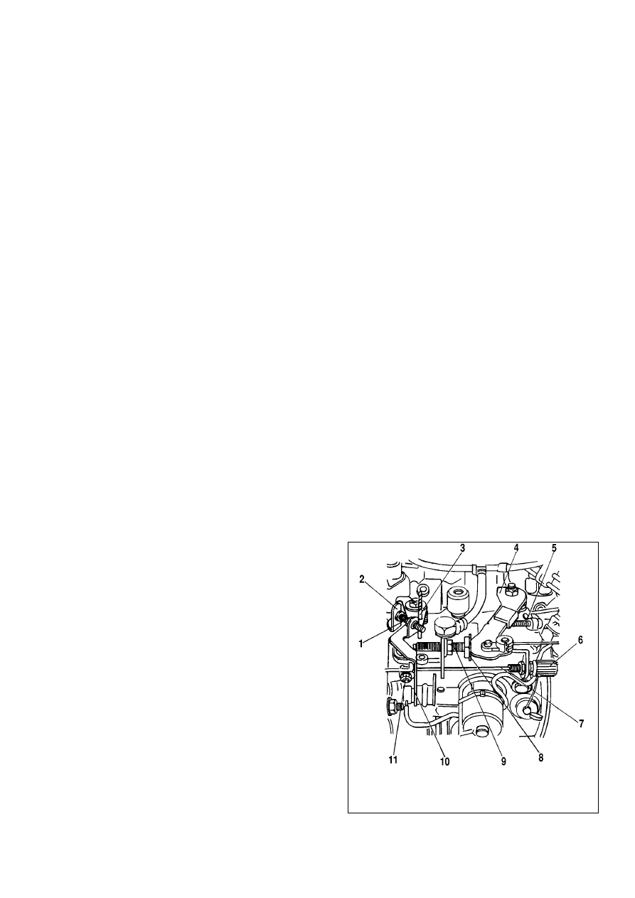
Fig.9-24. Idle control:
1 - throttle stop (CO adjustment) screw; 2 - stop lever; 3 - locating pin; 4 - load
lever; 5 - limiter; 6 - outer cable tensioner; 7 - accelerator cable; 8 - gasket; 9 -
limiter; 10 - fast idle lever; 11 - cable tensioner
Adjust idle with the help of screw 1. The idle speed should be
800-850 rpm.
Engine rundown - checking. Using load lever 4 set the
engine speed at 3000 rpm. Release the load lever, the engine
rundown should be 2.5 - 3.5 seconds.
After returning to idle, the speed difference should not exceed
50 rpm.
WARNING. The adjustment screws for maximum fuel
feed and speed are sealed at the factory.
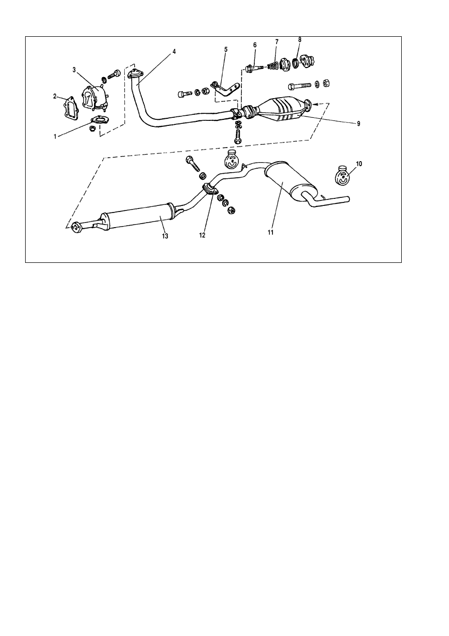
Exhaust emission system
Exhaust gases escape from the engine through exhaust man-
ifold 3 (Fig.9-25), front exhaust pipe (downpipe) 4, catalytic con-
verter 9, intermediate silencer 13 and front silencer 11.
There is a steel heat shield over the catalytic converter.
Exhaust gasket 1 is fitted between the downpipe flange and
exhaust manifold 1.
The downpipe is connected to the catalytic converter flange
through a moving joint. Metal/graphite ring 8 with a spherical sur-
face is placed between the flanges, an inner spherical surface is
provided in the flange of the downpipe.
The silencer pipes are held together by means of clasp 12.
Downpipe 4 is attached by three nuts to the exhaust manifold and
in addition to bracket 5.
No dismantling or repair of the silencers or pipes is possible,
have them always replaced with new ones.
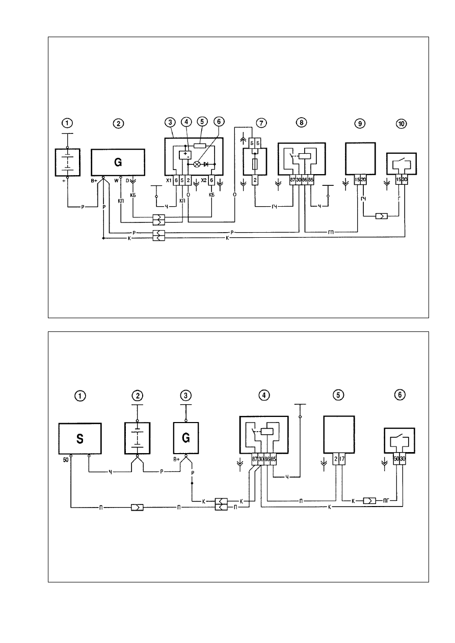
Electrical system
Alternator. The Valeo alternator is supplied together with the
engine. The wiring diagram for alternator is shown in Fig.9-26.
When the ignition is switched on, the alternator «Ç» terminal
is powered through warning light 6. After the engine start current
is not supplied through the warning light and it does not illumi-
nate. The alternator «W» terminal is used for voltage supply to
electronic tachometer 4.
Starter motor. The Valeo starter motor is supplied together
with the engine. The wiring diagram for starter motor is shown in
Fig.9-27.
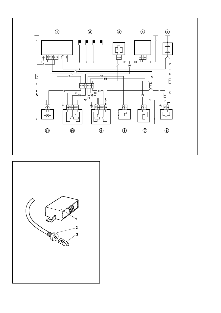
Engine management system (EMS). The wiring diagram
for the engine management system is shown in Fig.9-28.
The system design, operation and diagnostics are detailed in
a separate «Peugeot» Manual for Diesel Engine Diagnostics.
Vehicle antitheft system. The vehicle VAZ-21215-10 is fit-
ted with an antitheft system of relay type (Äèë-2ê).
The antitheft system includes control module 1 (Fig.9-29),
system state indication LED 2 and code key fobs 3. The theft-
deterrent system represents an electronic control module, which
allows in case of unauthorized use to inhibit the engine start
through disconnecting the relevant electrical circuits.
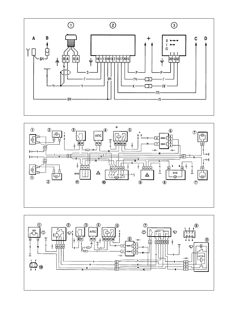
Refer to Fig.9-30 for the wiring diagram of theft-deterrent sys-
tem. The installation of the antitheft system brought alterations in
operation of direction indicators and hazard flashers (Fig.9-31),
windscreen wipe/wash (Fig.9-32), rear window wipe/wash and
heating (Fig.9-33).
203
Fig.9-25. Exhaust emission system:
1 - exhaust gasket; 2 - gasket; 3 - exhaust manifold; 4 - downpipe; 5 - bracket, downpipe; 6 - bolt; 7 - helical spring; 8 - sealing ring; 9 - catalytic converter; 10 - suspen-
sion loop; 11 - main silencer; 12 - clasp; 13 - front silencer
204
Fig.9-26. Wiring diagram for alternator:
1 - battery; 2 - alternator; 3 - instrument cluster; 4 - digital tachometer; 5 - resistor 50 éhm, 5 W; 6 - low battery warning light; 7 - fusebox; 8 - ignition relay; 9 - control mod-
ule, theft-deterrent system; 10 - ignition switch
Fig.9-27. Wiring diagram for starter motor:
1 - starter motor; 2 - battery; 3 - alternator; 4 - ignition relay; 5 -control module, theft-deterrent system; 6 - ignition switch
Headlight wipe/wash. The vehicle VAZ-21215-10 is not fit-
ted with the headlight wipe/wash.
Cooling fan motor. Two dc motors powered from constant
magnets of MP 8019/37 type are provided to operate the engine
cooling fan blower. The wiring diagram for cooling fan motor is
shown in Fig.9-34.
The motors are triggered by sensor 1 through complementary
relay 3. The sensor is fitted to the right-hand radiator cooler. The
sensor contacts close at (99±3)°ë and open at (94±3)°ë. The
relay is housed in the engine bay and is bolted to the top bulk-
head reinforcement.
The motors are maintenance-free and must always be
renewed in case of failure.
Motor specification
Nominal motor shaft speed with impeller
load, rpm . . . . . . . . . . . . . . . . . . . . . . . . . . . . . . . . . .600-2800
Current consumption at speed and
load as specified, ampere, not greater . . . . . . . . . . . . . . . . .14
Instrument cluster. The instrument cluster includes:
speedometer with trip counter, coolant temperature gauge, fuel
gauge, tachometer, 13 warning lights (Fig.9-35). The wiring dia-
gram for instrument cluster is shown in Fig.9-36. The instrument
panel pin assignment is shown in Table 9-3.
205
Fig.9-28. Wiring diagram for Engine Management System:
1 - glow plug control module; 2 - glow plugs; 3 - EGR valve; 4 - fuel pump; 5 - battery; 6 - ignition switch; 7 - breaker; 8 - thermoswitch; 9 - relay, EGR valve; 10 - relay,
thermoswitch; 11 - glow plug warning light
Fig.9-29. Automotive theft-deterrent system:
1 - control module; 2 - LED for system state indication; 3 - key fob
206
Fig.9-30. Wiring diagram for theft-deterrent system:
1 - LED for system state indication; 2 - control module; 3 - ignition switch;
Ä - to interior light switch; Ç - to interior light; ë - to ignition relay terminal 86; D - to starter relay terminal 86
Fig.9-31. Wiring diagram for direction indicators and hazard warning flashers:
1 - direction indicators, front lights; 2 - side repeat indicators; 3 - ignition switch; 4 - control module, theft-deterrent system; 5 - ignition relay; 6 - fuse and relay box; 7 - direc-
tion indicators, rear lights; 8 - direction indicator warning light in instrument cluster; 9 - indicators flasher relay; 10 - hazard warning flasher switch; 11 - direction indicator
switch
Fig.9-32. Wiring diagram for windscreen wipe/wash:
1 - windscreen washer motor; 2 - windscreen wiper motor; 3 - ignition switch; 4 - control module, anti-theft system; 5 - ignition relay; 6 - fusebox; 7 - windscreen wipe/wash
switch; 8 - pin assignment in switch connector; 9 - windscreen wiper relay; 10 - pin assignment in windscreen wiper relay and motor connectors.
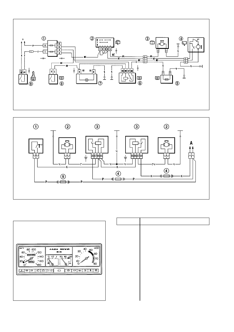
Table 9-3.
Instrument cluster pin assignment
Pin No
Pin assignment
Connector ï1 (red or amber)
1
-
2
To ignition switch terminal «15»
3
Spare
4
To instrument cluster lighting switch
5
To alternator terminal «W»
6
To housing
7
To ignition switch terminal «50»
8
To handbrake warning light switch
9
To seat belt relay
10
To fuel gauge terminal «W»
11
To differential lockup sensor
12
To low oil pressure sensor
13
To brake fluid level sensor
207
Fig.9-33. Wiring diagram for tailgate wipe/wash and heating element:
1 - fusebox; 2 - wipe/wash switch; 3 - rear window washer motor; 4 - rear window wiper motor; 5 - rear window heating element; 6 - heated rear window relay; 7 - heated
rear window warning light; 8 - heated rear window switch; 9 - ignition switch
Fig.9-34. Wiring diagram for cooling fan motors:
1- motor-on sensor; 2 - fan blower motor; 3 - fan motor cut-in relay; 4 - fuse (8 ampers) 5 - fuse (16 amperes)
Fig.9-35. Instrument cluster
Wyszukiwarka
Podobne podstrony:
Rokitnik kontra nowotwory trochę danych szczegółowych
Teoria (troche), Studia, Semestr II, Algorytmy i struktury danych
Silniki, Troche techniki E30 i nietylko
Dany jest silnik asynchroniczny trójfazowy, Dany jest silnik asynchroniczny trójfazowy ( 3 - fazowy
V semestr, praca kontrolna Piotr Zając, Silnik obcowzbudny prądu stałego o danych znamionowych: PN =
Podstawowe silniki baz danych
Systemy Baz Danych (cz 1 2)
silniki prądu stałego
PODSTAWY STEROWANIA SILNIKIEM INDUKCYJNYM
04 Zabezpieczenia silnikówid 5252 ppt
SILNIKI GRAFICZNE W GRACH KOMPUTEROWYCH
1 Tworzenie bazy danychid 10005 ppt
Hurtownie danych Juranek
bd cz 2 jezyki zapytan do baz danych
SILNIKI
Prezentacja OP silniki
bazy danych II
więcej podobnych podstron