Operating Instructions for
PROFIBUS-DP Communications Modules
for Siemens General Purpose Inverters
CB15 CB155
MICROMASTER
COMBIMASTER
MICROMASTER Vector
MICROMASTER Integrated
MIDIMASTER Vector
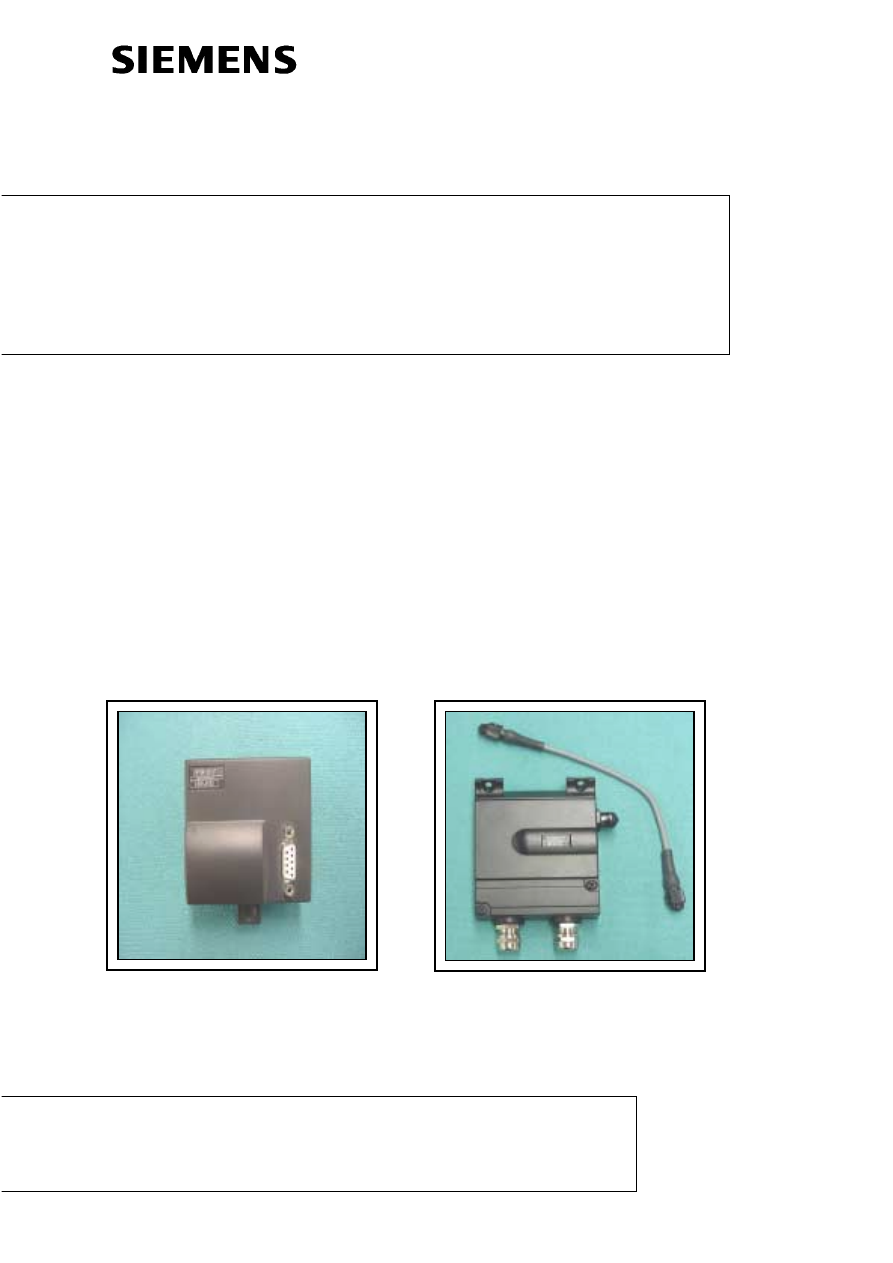
PROFIBUS-DP Communications Module
CB15/CB155
Operating Instructions

© Siemens plc 2000 / 2001
ISSUE-C1
2
10/04/01
PAGE LEFT INTENTIONALLY BLANK

English
CONTENTS
© Siemens plc 2000 / 2001
ISSUE-C1
3
10/04/01
List of
Contents

English
CONTENTS
© Siemens plc 2000 / 2001
ISSUE-C1
4
10/04/01
List of Figures
Figure 1-1: Data Structure in the PROFIBUS - DP Message Frame......................................................... 7
Figure 2-1: CB15 Front Panel................................................................................................................ 10
Figure 2-2 Typical Installation Diagram for CB155 (6SE9996 –0XA18) .................................................. 11
Figure 2-3: Diagram of Pin Arrangements for the 5 - way circular PROFIBUS Connector ....................... 12
Figure 2-4: Typical Installation Diagrams for CB155 – (6SE9996 –0XA17)............................................. 14
Figure 2-5: Diagram of CB155 (up to Issue K) Terminator Switch set to terminate at both ends.............. 17
Figure 2-7: Diagram of CB155 (later than issue L) Terminator Switch. ................................................... 17
List of Tables
Table 2-1 : CB15 PROFIBUS Transmission Rates and Cabling ............................................................... 9
Table 2-2: PROFIBUS Connector Pin Arrangements ............................................................................. 12
Table 2-3 : CB155 PROFIBUS Transmission Rates and Cabling ........................................................... 12
Table 2-4 : CB155 PROFIBUS Transmission Rates and Cabling ........................................................... 16
Table 3-1: CB15/CB155 Parameters ..................................................................................................... 20
Table 4-1: CB15/CB155 Fault Codes..................................................................................................... 21
Table 5-1: Structure of the User Data in the PROFIBUS - DP Message Frame ..................................... 22
Table 5-2: Parameter Process Data Object (PPO Types)....................................................................... 22
Table 5-3: Structure of the Parameter Area ........................................................................................... 23
Table 5-4: Task Identifier (Master
Table 5-5: Reply Identifiers (Inverter - Master) ....................................................................................... 24
Table 5-6: Reply Error Codes (Inverter - Master) ................................................................................... 24
Table 5-7: Parameter Identifier Example................................................................................................ 24
Table 5-8: Parameter Value Example .................................................................................................... 25
Table 5-9: Process Data Area ............................................................................................................... 26
Table 5-10: Bit Word Definition.............................................................................................................. 27
Table 5-11: Status Word Definition ........................................................................................................ 28
Table 5-12: Value Table for the Identification Bytes ............................................................................... 30
Table 6-1: PROFIBUS Diagnostic Parameters....................................................................................... 31

English
WARNINGS AND CAUTIONS
© Siemens plc 2000 / 2001
ISSUE-C1
5
10/04/01
Warning and Caution Notes
WARNING
Hazardous voltages are present in this electrical equipment during operation.
Non-observance of the safety instructions can result in severe personal injury or
death.
Only qualified personnel should work on or around this equipment after becoming
thoroughly familiar with all warnings, safety notices and maintenance procedures
contained herein.
The successful and safe operation of this equipment is dependent on proper handling,
installation, operation and maintenance.
Definitions
-Qualified Person
For the purposes of this manual and product labels, a qualified person is one who is familiar with the
installation, construction, operation and maintenance of this equipment and with the hazards involved.
In addition, the person must be:
(1)
Trained and authorised to energise, de-energise, clear, ground and tag circuits and
equipment in accordance with established safety practices.
(2)
Trained in the proper care and use of protective equipment in accordance with established
safety practices.
(3)
Trained in rendering first aid.
-DANGER
For the purposes of this manual and product labels, DANGER indicates that loss of life, severe personal
injury or substantial property damage WILL result if proper precautions are not taken.
-WARNING
For the purposes of this manual and product labels, WARNING indicates that loss of life, severe
personal injury or substantial property damage CAN result if proper precautions are not taken.
-CAUTION
For the purposes of this manual and product labels, CAUTION indicates that minor personal injury or
property damage CAN result if proper precautions are not taken.
-Note
For the purposes of this manual, and product labels, Notes merely call attention to information that is
especially significant in understanding and operating the drive.

English
1. OVERVIEW
© Siemens plc 2000 / 2001
ISSUE-C1
6
10/04/01
1 OVERVIEW
1.1 Description and Features
The PROFIBUS Module (CB15/CB155) is a device that allows control of an inverter over a
PROFIBUS-DP (SINEC L2-DP) serial bus.
The CB15 is for use with MICROMASTER, MICROMASTER VECTOR and MIDIMASTER Vector
inverters.
The CB155 is for use with COMBIMASTER and MICROMASTER Integrated inverters.
Features
-
Retains the ability to access the internal parameter set of the inverter (CB15 only).
-
Allows high-speed cyclical communication over a PROFIBUS link.
-
Ability to control up to 125 inverters using the PROFIBUS-DP protocol.
-
Provides open communication conforming to all relevant aspects of DIN19245 Part 3. It may
be used with any other PROFIBUS-DP peripheral on the serial bus.
-
Easy to install.
-
Easy to configure with proprietary Siemens software (parameterisation disc included).
-
Output frequency (and hence motor speed) can be controlled by one of five methods:
(1)
Digital frequency setpoint.
(2)
Analogue setpoint (voltage or current input).
(3)
Motor potentiometer.
(4)
Fixed frequency.
(5)
Remote data transmission via the PROFIBUS link.
IMPORTANT
The RS485 serial link is not available while the CB15/CB155 is connected to
the inverter.
1.2 Application on a PROFIBUS Link
PROFIBUS-DP is defined in standard in EN 50170. Data communication with the CB15/CB155
conforms to the specifications in the VDI/VDE 3689 ‘ PROFIBUS Profile for Variable Speed
Drives’ guideline. This defines the user data structure through which a master can access the
drive slaves. The user data structure is subdivided into two areas that can be transmitted in each
message frame:
Process data, i.e. control words and setpoints, or status information and actual values and
A parameter area for reading/writing parameter values, e.g. for reading out faults or
information on the attributes of a parameter, such as minimum/maximum limits, etc.
The structure of the user data is designated as Parameter Process data Objects (PPO) in the
PROFIBUS variable speed drives profile (VDI/VDE guideline 3689). There are five PPO types:
user data with no parameter area with two words or six words of process data, or user data with a
parameter area and two, six or ten words of process data.
The CB15/CB155 only supports PPO types 1 and 3.

English
1. OVERVIEW
© Siemens plc 2000 / 2001
ISSUE-C1
7
10/04/01
During installation of the network you can configure on the master which PPO type is used to
address the inverter from the PROFIBUS-DP master. The choice of PPO type depends on the task
of the drive within the automation network. The process data is always transmitted. It is processed
with the highest priority in the shortest time slices. The process data is used for open-loop control of
the drive in the automation network, e.g. switching on/off, specifying setpoints, etc.
The parameter area provides the user with free access on the network to all the parameters located
on the inverter, e.g. for reading out detailed diagnostics information, fault messages, etc. This
enables further information to be called up on a higher-level system, such as a PC, for visualisation
of the drive, without affecting the performance capabilities of process data communication.
1.2.1
Control and operation of the CB15/CB155 via PROFIBUS-DP
All information required for the open-loop control of a variable speed drive in the network
environment of an industrial process is transmitted in the process data area (see Figure 1). Control
information (control words) and setpoints are transmitted from the PROFIBUS-DP master to the
inverter. Information on the status of the inverter (status words) and actual values is transmitted in
the opposite direction.
User Data
Protocol Frame
(Header)
Protocol Frame
(Trailer)
Parameters (PKW)
Process Data (PZD)
Figure 1-1: Data Structure in the PROFIBUS - DP Message Frame
The communication component of the interface board stores the received process data in the order
in which it was transmitted in the message frame. Each word in the frame is assigned a fixed
function.
The CB15/CB155 supports the PROFIBUS-DP control commands FREEZE and SYNC.
A diagnostics parameter can be used to read detailed diagnostics information straight from the
diagnostics memory of the CB15/CB155.

English
2. INSTALLATION
© Siemens plc 2000 / 2001
ISSUE-C1
8
10/04/01
2 INSTALLATION
SECTION 2.1
CB155 Installation (6SE9996 –0XA18)
CB155 Installation (6SE9996 –0XA17)
2.3.2.1 CB155 Terminals (for Issue H and later Models – 6SE9996-0XA17) ....................................... 15
2.3.2.2 Issue Status: Up to and including issue I................................................................................. 15
2.3.2.3 Issue Status: K ....................................................................................................................... 15
2.3.2.4 Issue Status: L ...........................................................................Error! Bookmark not defined.
2.3.2.5 Bus
WARNING
Incorrect operation of the serial bus system can lead to an inverter being
switched on inadvertently. Commissioning work must only be carried out by
personnel who are qualified in installing such systems. Additionally, the
guidelines associated with the installation of the inverter itself must be followed
(see section 2 of the inverter’s handbook).

English
2.1. - CB15 INSTALLATION
© Siemens plc 2000 / 2001
ISSUE-C1
9
10/04/01
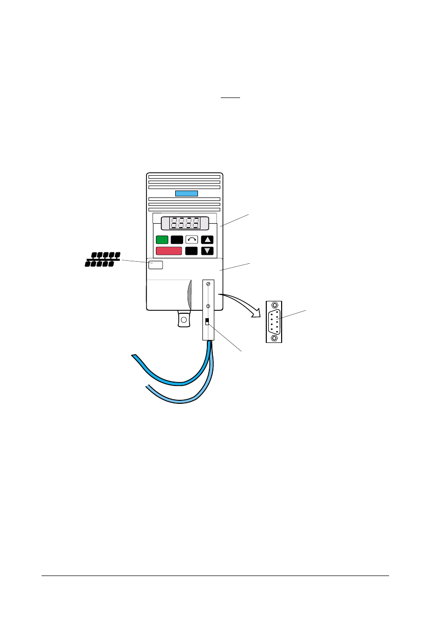
2.1 CB15
Installation
The inverter must be switched off before the CB15 is either connected or disconnected. The CB15
is powered directly from the inverter and therefore needs no additional external supply
2.1.1
Installing the Module
Fix the CB15 to the front of the inverter by mating the D-type connectors together and then
securing in position by pressing the module onto the inverter.
2.1.2
Connecting the Bus Cable
2.1.2.1 CB15
Terminals
The PROFIBUS connection must be made using the D-type socket on the front of the CB15.
Connections to this socket are as follows:
Pin 3 PROFIBUS B connection (Red)
Pin 8 PROFIBUS A connection (Green)
Additionally, the cable shield must be connected to the shell of the D-type connector, which is
connected to protective earth via the CB15 and inverter. The connector must be screwed
securely to the CB15 to ensure both mechanical strength and earth continuity.
Connectors from the 6ES7972 range are recommended with Profibus cable 6XV 1830-0EH10
Note
As the stations must be ‘ daisy-chained’ together (except for the stations at either end of the
bus), there must be two cables into the D-type connector - one from the previous station and
one to the next station.
This bus topology means that a station may be disconnected from the bus or powered down
while still connected without affecting bus operation.
2.1.2.2 Bus
Cabling
Transmission Rate (Kbits/s)
Max. Length of Cable in a Segment (m)
9,6
1200
19,2
1200
93,75
1200
187,5
1000
500
400
1500
200
12000
100
Table 2-1 : CB15 PROFIBUS Transmission Rates and Cabling
A segment can be expanded using RS485 repeaters. The SINEC L2 RS485 repeater (order no.
6GK1510-0AC00) is recommended.
2.1.2.3 EMC
Shielding
The conductors of the bus cables must be shielded and installed separately from the power
cables with a minimum clearance of 20 cm. The shield for the bus cable should be connected to
protective earth at both ends. This is achieved as follows:
For the CB15 use the P-clip provided with the module as shown in the enclosed instruction
sheet.
Bus and power cables should be installed at a crossing angle of 90º.
English
2.1. - CB15 INSTALLATION
© Siemens plc 2000 / 2001
ISSUE-C1
10
10/04/01
2.1.3 Bus
Termination
For interference-free operation of PROFIBUS-DP, the bus cable must be terminated at both ends
with bus terminating resistors. The bus cable from the first PROFIBUS-DP station to the last
PROFIBUS-DP station should be treated as a single bus cable, so that the PROFIBUS-DP
should be terminated twice.
For the CB15 this is achieved by moving the selector switch mounted on the D-type housing of
the PROFIBUS-DP connector to the ON position.
2.1.4 CB15-Front
Panel
SIEMENS
SIEMENS
1
0
Jog
Jog
P
MICROMASTER
Inverter
CB 15.Module
Front Panel Mounted
Female 9-Pin
D-Type Connector
P
I
F
O
R
B
S
U
Bus Terminator Switch
(set to ON)
Figure 2-1: CB15 Front Panel
English
2.2.- CB155 INSTALLATION (6SE9996 –0XA18)
© Siemens plc 2000 / 2001
ISSUE-C1
11
10/04/01
2.2 CB155 Installation (6SE9996 –0XA18)
The inverter must be switched off before the CB155 is either connected or disconnected. The
CB155 is powered directly from the inverter and therefore needs no additional external supply
2.2.1
Installing the Module
Before connecting the CB155 to the inverter, it is necessary to set the following parameters to the
correct values, using the OPM2 (Optional Clear Text display).
·
P009
Ü 3
Extended Parameter Set.
·
P099
Ü 1
Communications Adapter Type = PROFIBUS
·
P918
Ü [ ]
Slave Address – [ ] (i.e., PROFIBUS address)
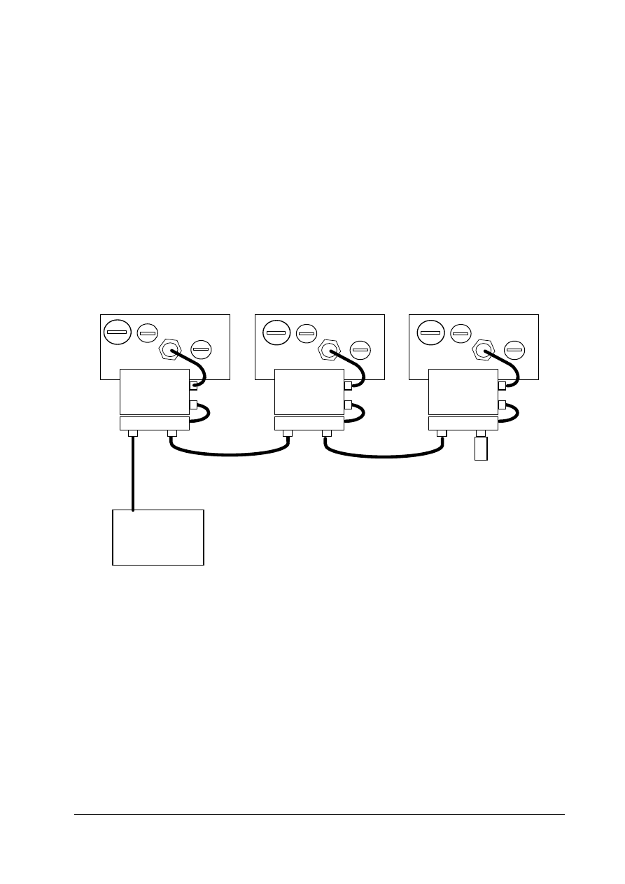
Fix the CB155 to the side of the inverter housing using the screws provided. Connect the CB155
to SK200 on the inverter, using the supplied cable.
TERM INATOR
T CONNECTOR
T CONNECTOR
T CONNECTOR
CB155
CB155
CB155
BUS MASTER
INTERCONNECTING CABLES - One or
more cables joined by cable links.
COMBIMASTER
COMBIMASTER
COMBIMASTER
Installation Accessories
PROFIBUS T- Connector
6SE9996-0XA21
PROFIBUS Terminator
6SE9996-0XA22
PROFIBUS Cable 1 metre
6SE9996-0XA23
PROFIBUS Cable 5 metre
6SE9996-0XA24
PROFIBUS Cable 10 metre 6SE9996-0XA25
PROFIBUS Cable link
6SE9996-0XA26
Diagram shows typical PROFIBUS installations using CB155 and COMBIMASTER
Figure 2-2 Typical Installation Diagram for CB155 (6SE9996 –0XA18)
When interfacing with a PLC or other slave using a Profibus D type connector, a cable 6SE9996-OXA23
has to be cut and the cores connected as follows:
Green to Profibus A connection.
Red
to Profibus B connection.

English
2.2.- CB155 INSTALLATION (6SE9996 –0XA18)
© Siemens plc 2000 / 2001
ISSUE-C1
12
10/04/01
2.2.2
Connecting the Bus Cable
2.2.2.1
CB155 Terminals (6SE9996-0XA18)
The PROFIBUS connection will normally be made using the optional T connector 6SE9996-
0XA21 ). This is connected to the free connector on the side of the CB155, and is in turn
screwed to the front of the CB155, thus providing the PROFIBUS IN and OUT connections. See
Diagram on Page 11.
1
2
3
4
5
1
2
3
4
5
Socket (Pins) Plug (Holes)
Figure 2-3: Diagram of Pin Arrangements for the 5 - way circular PROFIBUS Connector
Note that the socket is used on the PROFIBUS module, and the gender adapters. The plug is
used on the interconnecting cables.
Terminal
Function and/or information
1 +5V
2 PROFIBUS
A
(Green)
3 0V
4 PROFIBUS
B
(Red)
5 No
connection
Table 2-2: PROFIBUS Connector Pin Arrangements
2.2.2.2 Bus
Cabling
Transmission Rate (Kbits/s)
Max. Length of Cable in a Segment (m)
9,6
1200
19,2
1200
93,75
1200
187,5
1000
500
400
1500
200
12000
100
Table 2-3 : CB155 PROFIBUS Transmission Rates and Cabling
A segment can be expanded using RS485 repeaters. The PROFIBUS RS485 repeater (order no.
6GK1510-0AC00) is recommended.

English
2.2.- CB155 INSTALLATION (6SE9996 –0XA18)
© Siemens plc 2000 / 2001
ISSUE-C1
13
10/04/01
2.2.2.3 EMC
Shielding
The conductors of the bus cables must be shielded and installed separately from the power
cables with a minimum clearance of 20 cm. The shield for the bus cable should be connected to
protective earth at both ends.
For the CB155 (6SE9996 –0XA18) if the specified cables are used no further action is
necessary.
Bus and power cables should be installed at an angle of 90º.
2.2.3 Bus
Termination
For interference-free operation of PROFIBUS-DP, the bus cable must be terminated at both ends
with bus terminating resistors. The bus cable from the first PROFIBUS-DP station to the last
PROFIBUS-DP station should be treated as a single bus cable, so that the PROFIBUS-DP
should be terminated twice.
For the CB155 (6SE9996 –0XA18) this is achieved by fitting the dedicated terminating connector
to the free position on the T connector at the end of the link.
Note
(1) Ensure that you only connect/activate the bus terminator to the first network station and the
last network station.
English
2.3. - CB155 INSTALLATION (6SE9996 –0XA17)
© Siemens plc 2000 / 2001
ISSUE-C1
14
10/04/01
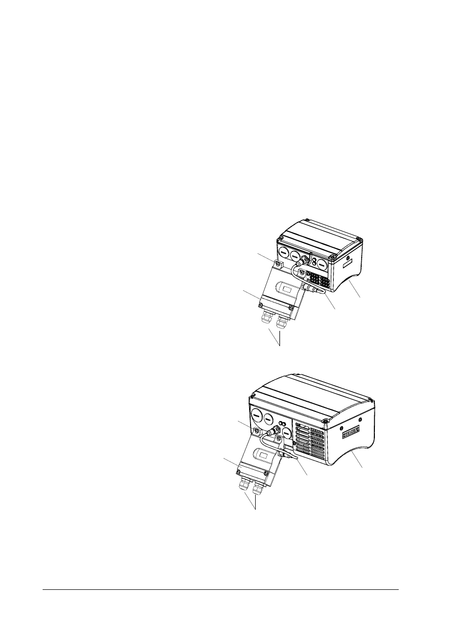
2.3 CB155 Installation (6SE9996 –0XA17)
The inverter must be switched off before the CB155 is either connected or disconnected. The
CB155 is powered directly from the inverter and therefore needs no additional external supply
2.3.1
Installing the Module
Before connecting the CB155 to the inverter, it is necessary to set the following parameters to the
correct values, using the OPM2 (Optional Clear Text display).
·
P009
Ü 3
Extended Parameter Set.
·
P099
Ü 1
Communications Adapter Type = PROFIBUS
·
P918
Ü [ ]
Slave Address – [ ] (i.e., PROFIBUS address)
Fix the CB155 to the side of the inverter housing using the screws provided. Connect the CB155
to SK200 on the inverter, using the supplied cable. Installation should be as shown in the
diagrams below
Combimaster
Connection Cable
Cable Glands
CB155 Module Retaining Screws
Termination PCB housing:
remove cover retention
screws to obtain access.
Case Size A (CSA)
Combimaster
Connection Cable
Cable Glands
CB155 Module Retaining Screws
Termination PCB housing:
remove cover retention
screws to obtain access.
Case Size B (CSB)
Diagram shows typical PROFIBUS installations using CB155 and COMBIMASTER
Figure 2-4: Typical Installation Diagrams for CB155 – (6SE9996 –0XA17)
English
2.3. - CB155 INSTALLATION (6SE9996 –0XA17)
© Siemens plc 2000 / 2001
ISSUE-C1
15
10/04/01
2.3.2
Connecting the Bus Cable
2.3.2.1
CB155 Terminals (for Issue H and later Models – 6SE9996-0XA17)
The PROFIBUS connection are made using the terminals on the termination PCB. This is located
directly beneath the removable access cover. It will be necessary to remove the two retaining
screw to gain access.
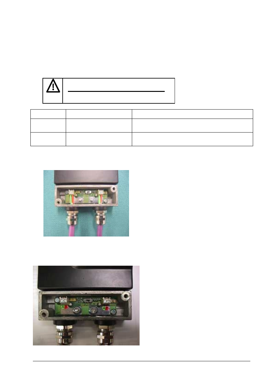
WARNING
PLEASE CHECK ISSUE STATUS OF PRODUCT
AND REFER TO FOLLOWING TABLE
CB155
Issue Status
Wiring Guidelines
Up to and including issue I
See Photo 2.3.2.2 below
Note: PCB labelling incorrect
Issue K
See Photo 2.3.2.3 below
Note: See correction label
2.3.2.2
Issue Status: Up to and including issue I
Connect Profibus cores as shown
Note: Terminal marking is incorrect
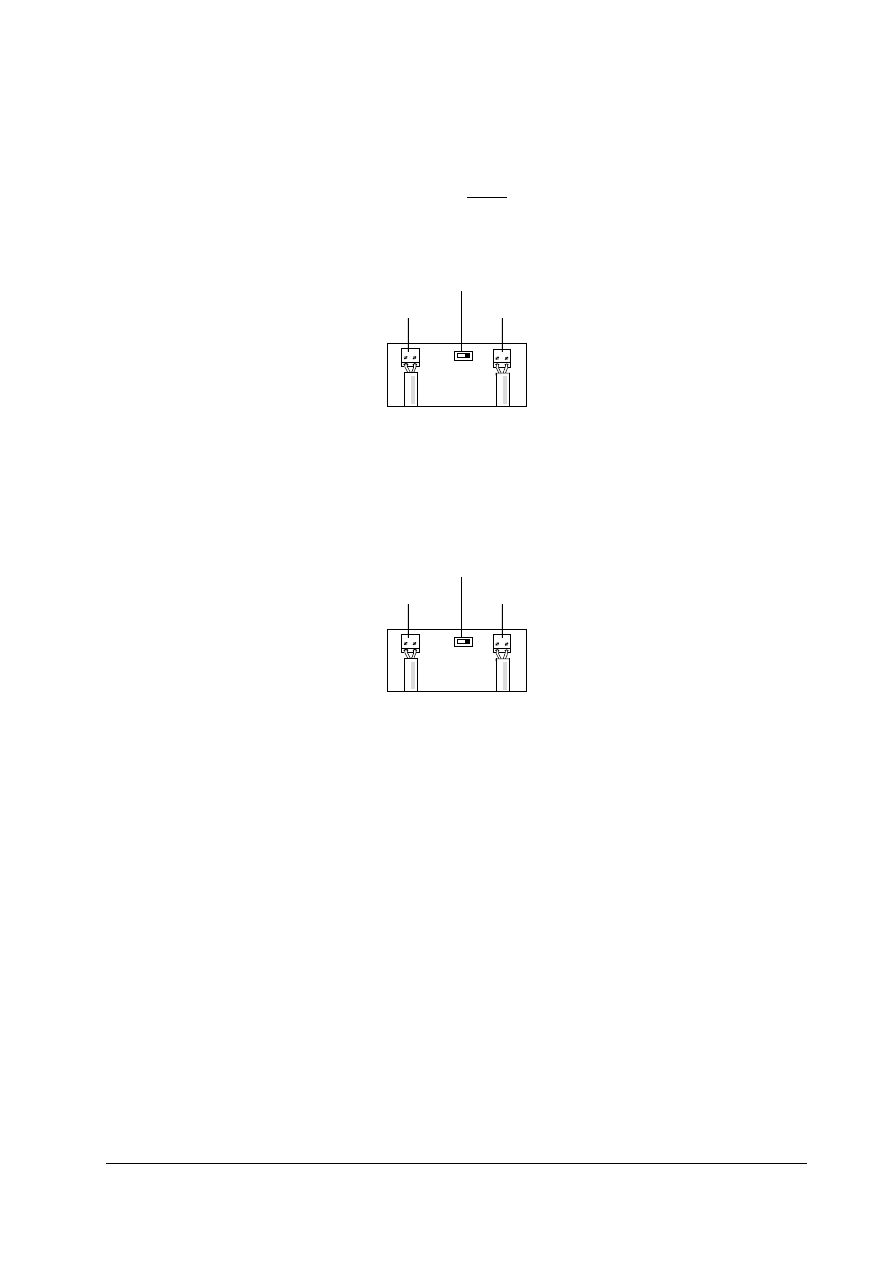
2.3.2.3
Issue Status: K
Refer to terminal label (A / B), Connect Profibus
cores accordingly.

English
2.3. - CB155 INSTALLATION (6SE9996 –0XA17)
© Siemens plc 2000 / 2001
ISSUE-C1
16
10/04/01
2.3.2.4 Bus
Cabling
Transmission Rate (Kbits/s)
Max. Length of Cable in a Segment (m)
9,6
1200
19,2
1200
93,75
1200
187,5
1000
500
400
1500
200
12000
100
Table 2-4 : CB155 PROFIBUS Transmission Rates and Cabling
A segment can be expanded using RS485 repeaters. The SINEC L2 RS485 repeater (order no.
6GK1510-0AC00) is recommended.
2.3.2.5 EMC
Shielding
The conductors of the bus cables must be shielded and installed separately from the power
cables with a minimum clearance of 20 cm. The shield for the bus cable should be connected to
protective earth at both ends.
For the CB155 (6SE9996 –0XA17) the cable gland connects the bus shield to the protective
earth.
Bus and power cables should be installed at an angle of 90º.
English
2.3. - CB155 INSTALLATION (6SE9996 –0XA17)
© Siemens plc 2000 / 2001
ISSUE-C1
17
10/04/01
2.3.3 Bus
Termination
For interference-free operation of PROFIBUS-DP, the bus cable must be terminated at both ends
with bus terminating resistors. The bus cable from the first PROFIBUS-DP station to the last
PROFIBUS-DP station should be treated as a single bus cable, so that the PROFIBUS-DP
should be terminated twice.
For the CB155 (up to Issue K) this is achieved by setting the Terminator switch to the ‘IN’ position
marked on the PCB as shown below.
IN
Figure 2-5: Diagram of CB155 (up to Issue K) Terminator Switch set to terminate at both ends.
For the CB155, (later than issue L), this is achieved by switching the Terminator switch to the
‘ON’ position marked on the PCB as shown below.
ON
OFF
Figure 2-7: Diagram of CB155 (later than issue L) Terminator Switch.
Note
(1) Ensure that you only connect/activate the bus terminator to the first network station and the last
network station.
Terminator Switch
Terminals
Terminals
Terminator Switch
Terminals
Terminals

English
2.4. - CB15/CB155 INSTALLATION (common information)
© Siemens plc 2000 / 2001
ISSUE-C1
18
10/04/01
2.4 EMC
Measures
The following measures are required for interference-free operation of the PROFIBUS-DP.
Additional information on EMC precautions can be found in the ‘ET 200 Distributed I/O System’
manual.
2.4.1 Equipotential
Bonding
If the cable shields are earthed at different sections of the system then equipotential bonding
cables can be used to reduce current flow in the screen between the inverters and the
PROFIBUS-DP master.
The following equipotential cables are recommended:
16 mm
2
Cu for equipotential bonding conductors up to 200m in length.
25 mm
2
Cu for equipotential bonding conductors over 200m in length.
Use a large contact surface connection between the equipotential bonding conductors and the
protective ground conductor.
2.4.2 Cable
Installation
Observe the following rules when installing cables:
-Bus cables (signal cables) may not be installed directly adjacent to power cables.
-Signal cables (and equipotential bonding cables) should be connected across the shortest
possible path.
-Power cables and signal cables must be installed in separate cable runs.
-Shields should have low impedance connections (large surface area).

English
3. OPERATING INFORMATION
© Siemens plc 2000 / 2001
ISSUE-C1
19
10/04/01
3 OPERATING
INFORMATION
3.1 Local
Control
The inverter will operate a motor in an identical manner to that described in the operating
instructions for the inverter.
3.2 Remote
Control
Different modes of remote control are available via the serial link (refer to parameters P927 and
P928 in section 3.3.2 below for details).
3.3 System
Parameters
The basic parameter set used by the CB15/CB155 is identical to that used for the inverter.
However, some parameters cannot be accessed because either they are not required or they have
been replaced by PROFIBUS parameters.
3.3.1
Parameters not Available via the CB15/CB155
P091
Slave address (replaced by P918)
P092
Baud rate (replaced by P963)
P093
USS Timeout
P121 - P124
Enable/Disable control keys
P910
Local/Remote mode (replaced by P927 and P928)
P922
Software version (replaced by P702)
P923
Equipment system number (replaced by P701)
P930
Fault log (replaced by P947: the last 4 Fault Codes are also in P140-143
P931
Last Warning (replaced by P958)
3.3.2
Parameters Specific to the CB15/CB155
Note
D
D
D
D
= Parameters marked thus can be changed while the drive is running.
Parameter
Function
Range
[Default]
Description / Notes
P700 Software
version,
PROFIBUS module
00.00 - 99.99
[-]
Contains the software version number of the
PROFIBUS module and cannot be changed.
P701
D
D
D
D
Equipment system number
0 - 255
[0]
You can use this parameter to allocate a unique
reference number to the inverter. It has no
operational effect.
P702
Software version
00.00 - 99.99
[-]
Contains the software version number of the
inverter and cannot be changed
P880 Indexed
parameter
diagnostic data
-
This parameter contains data relating to the
PROFIBUS-DP function
(see section 6.1).
P918
D
D
D
D
PROFIBUS-DP slave
address
1 - 126
[126]
Sets the bus address (range 1 to 126) for the
RS485 serial interface with PROFIBUS-DP
protocol.
P927
D
D
D
D
PROFIBUS-DP
local/remote parameter
control
0 - 1
[0]
Sets local or remote parameter control via the
RS485 interface:
0 = Local parameter control
1 = Remote parameter control

English
3. OPERATING INFORMATION
© Siemens plc 2000 / 2001
ISSUE-C1
20
10/04/01
P928
D
D
D
D
PROFIBUS-DP
local/remote state control
0 - 3
[0]
Sets local or remote state control via the RS485
interface:
0 = Full local control
1 = Full remote control
2 = Partial local control (remote control of
frequency)
3 = Partial remote control (local control of
frequency)
Note: If P928 is set to 1 or 2, the analogue input
is active when P006 is set to 1.
P947
Indexed parameter fault log
-
Index = n000 Contains latest unacknowledged
fault or error code.
Index = n001 to n007 Fixed at 0000.
Index = n008 Contains latest acknowledged fault
or error code.
Index = n009 to n015 Fixed at 0000.
P958
Last Warning code
0 - 9999
[-]
The last warning that occurred is shown in this
parameter until power is removed:
Refer to Parameter P931 description in Inverter
Operating instructions.
.
P963
PROFIBUS-DP baud rate
0 - 10
[-]
Shows the bit rate of the PROFIBUS-DP serial
bus set automatically in PROFIBUS mode (read
only):
0 = Baud rate not found
1 = Baud rate = 9600 Baud
2 = Baud rate = 19,2 KBaud
3 = Baud rate = 45,45 KBaud
4 = Baud rate = 93,75 KBaud
5 = Baud rate = 187,5 KBaud
6 = Baud rate = 500 KBaud
7 = Baud rate = 1,5 MBaud
8 = Baud rate = 3,0 MBaud
9 = Baud rate = 6,0 MBaud
10 = Baud rate = 12,0 Mbaud
P967 Control
word
see section
3.3.3
Shows the latest received control word in hex
format (see section 3.3.3).
P968 Status
word
see section
3.3.3
Shows the latest status control word in hex format
(see section 3.3.3).
P970
Reset to factory default
settings
0 - 1
[1]
Set to ‘0’ and then press P to reset all parameters
except P101 to the factory default settings.
Table 3-1: CB15/CB155 Parameters
3.3.3
Hex Display for PROFIBUS on CB15
Several PROFIBUS-DP parameters are displayed in hex format using the four digit 7-segment
display on the inverter.
Parameter P967 - Control word
Parameter P968 - Status word

English
4. FAULT CODES
© Siemens plc 2000 / 2001
ISSUE-C1
21
10/04/01
4 FAULT
CODES
Fault codes are displayed and acknowledged for the CB15/CB155 in the same way as on the
inverter. Several new error codes specific to PROFIBUS have been added and are described below.
Further help may be found in section 5 (PROFIBUS Commissioning) and section 6 (PROFIBUS
Troubleshooting).
Fault Code
Cause
Corrective Action
F030 *
Interruption to
received
PROFIBUS-
telegrams
Check that the bus connections are not inverted or shorted.
Check that the bus connections between master and slave
are continuous.
Check that the baud rate is between 9.6 KBd and 12 MBd.
Check that the slave address is correct and unique.
Check that the required inverter has been included in the
configuration information for the master. (If using IM308B/C,
Check that the inverter has been included in the slave list.)
Check that the master is sending telegrams of the correct
type (PPO1 or PPO3).
Check that the master is running correctly (IM308B/C is in
RUN mode).
Check that the slave type is correct. (If using IM308B/C, use
the configuration file on the supplied floppy disc to set the
correct slave type for the CB15/CB155 when configuring with
COM ET 200).
F031
Link to inverter
failed
Check the integrity of CB15/CB155 mounting to inverter.
F033 *
PROFIBUS
telegram error
Reconfigure the master to send telegrams of the correct type
(i.e. PPO type 1 or PPO type 3 - see section 6).
F036
Program fault
Switch off power and then switch on again.
Table 4-1: CB15/CB155 Fault Codes
· These faults relate to communication problems and will only cause the inverter to trip if it is under
remote control (P928 = 1 or 3).
English
5. COMMISSIONING
© Siemens plc 2000 / 2001
ISSUE-C1
22
10/04/01
5 COMMISSIONING
5.1 Data Communication via PROFIBUS-DP
The structure of the user data is designated as parameter process data objects (PPO) in the
PROFIBUS variable speed drives profile:
U s e r D a t a
Parameter (PKW)
Process Data (PZD)
Protocol Frame
(Header)
Protocol Frame
(Trailer)
Table 5-1: Structure of the User Data in the PROFIBUS - DP Message Frame
There is user data with a parameter area (PKW) and a process data area (PZD) and user data that
consists exclusively of process data. The PROFIBUS variable speed drives profile defines five
PPO types. The PPO type is defined in the PROFIBUS-DP master parameter settings.
PKW
PZD
PKE
IND
PWE
PZD1
STW1
ZSW1
PZD2
HSW
HIW
PZD
3
PZD
4
PZD
5
PZD
6
PZD
7
PZD
8
PZD
9
PZD1
0
1st
Word
2nd
Word
3rd
Word
4th
Word
1st
Word
2nd
Word
3rd
Word
4th
Word
5th
Word
6th
Word
7th
Word
8th
Word
9th
Word
10th
Word
PPO1
PPO2
PPO3
PPO4
PPO5
PKW:
PZD:
PKE:
IND:
PWE:
STW1:
ZSW1:
HSW:
HIW:
Parameter identifier value
Process data
Parameter identifier
Index
Parameter value
Control word 1
Status word 1
Main setpoint
Main actual value
Table 5-2: Parameter Process Data Object (PPO Types)
Note
The CB15/CB155 only supports PPO types 1 and 3.

English
5. COMMISSIONING
© Siemens plc 2000 / 2001
ISSUE-C1
23
10/04/01
5.1.1
Parameter Area (PKW)
The parameter area can be used to control and monitor parameters (read/write) with PPO type 1
only.
Parameter Identifier
(PKE)
1st word
Bit No.:
15
12
11
10
0
AK
SPM
PNU
Parameter Index
(IND)
2nd word
Bit No.:
15
8 7
0
Index
Value = 0
Parameter Value
(PWE)
Parameter Value High
(PWE1)
3rd word
Parameter Value Low
(PWE2)
4th word
AK:
SPM:
PNU:
Task or reply identifier
Toggle bit for spontaneous message processing
Parameter number
Table 5-3: Structure of the Parameter Area
Parameter Identifier (PKE) (1st Word)
The parameter identifier (PKE) is always a 16-bit value.
Bits 0 to 10 contain the number of the desired parameter (PNU). Refer to the listing in the Operating
Instructions for the inverter.
Bit 11 is the toggle bit for spontaneous messages. The CB15/CB155 does not support this function!
Bits 12 to 15 contain the task or reply identifier (AK).
Only certain reply identifiers are possible depending on the task identifier. If the reply identifier has a
value of 7 (task not executable), an error number is stored in parameter value 2 (PWE2).
Task
Identifier
Meaning Answer
Identifier
Positive Negative
0
No task
0
7 or 8
1
Request parameter value
1
7 or 8
2
Change parameter value (word)
2
7 or 8
4
Request description element
3
7 or 8
6
Request parameter value (array word)
4
7 or 8
9
Request number of array elements
6
7 or 8
otherwise
-
7 or 8
Table 5-4: Task Identifier (Master
à Inverter)

English
5. COMMISSIONING
© Siemens plc 2000 / 2001
ISSUE-C1
24
10/04/01
Reply
Identifier
Meaning
0 No
reply
1
Transmit parameter value (word)
3
Transmit description element
4
Transmit parameter value (array word)
6
Transmit number of array elements
7
Task not executable (with error number)
8
No exclusive use of PKW interface
Table 5-5: Reply Identifiers (Inverter - Master)
Error
Number
Meaning
0 No
reply
1
Parameter value cannot be changed
2
Lower or upper value limit exceeded
3 Error
in
sub-index
4
Not an array
5
Incorrect data type
7
Description element cannot be changed
9
Description data does not exist
Table 5-6: Reply Error Codes (Inverter - Master)
Example:
Fixed setpoint 1: P41 = 29 (HEX)
Change parameter value.
Parameter Identifier (PKE)
1st word
Bit No.:
15
12
11
10
0
AK
SPM
PNU
0
0
1
0
0
0
0
0
0
0
1
0
1
0
0
1
Binary value
2
0
2
9
HEX value
Bit 12 .. 15: Value = 2 (= ‘2’ Hex); change parameter value (word)
Bit 0 .. 11:
Value = 41 (= ‘29’ Hex); parameter number without enabled spontaneous message bit
Table 5-7: Parameter Identifier Example
Parameter Index (IND) (2nd Word)
The index (also referred to as a subindex in the PROFIBUS profile) is an 8-bit value and is always
transmitted on PROFIBUS-DP in the most significant byte (bits 8 to 15) of the parameter index
(IND); the least significant byte (bits 0 to 7) of the parameter index (IND) has the value 0.
The index is not used for the inverter’s basic parameter set.

English
5. COMMISSIONING
© Siemens plc 2000 / 2001
ISSUE-C1
25
10/04/01
Parameter Value (PWE) (3rd and 4th Word)
The parameter value (PWE) is always transmitted as a double word (32 bits). Only one parameter
value can be transmitted in a frame.
A 32-bit parameter value is composed of PWE1 (most significant word, 3rd word) and PWE2 (least
significant word, 4th word).
A 16-bit parameter value is transmitted in PWE2 (least significant word, 4th word). In this case
PWE1 (most significant word, 3rd word) must be set to value 0 on the PROFIBUS-DP master.
Example:
Fixed setpoint 1: P41 = 29 (HEX)
Change parameter value to 30 (DEC) = 1E (HEX)
Parameter Value
(PWE)
Bit No.:
31
24 23
16
3rd word (PWE1) (Hex)
0
0
0
0
Bit No.:
15
8 7
0
4th word (PWE2) (Hex)
0
0
1
E
Bit 0 .. 15:
Parameter value for 16-bit parameter or low part for 32-bit parameter
Bit 16 .. 31: Value = 0 for 16-bit parameter or high part for 32-bit parameter
Table 5-8: Parameter Value Example
5.1.2 Rules for Task/Reply Processing
- One task or one reply can only ever refer to one parameter value.
- The master must repeat a task until it has received the appropriate reply.
- The master detects the reply to an issued task:
Evaluation of the reply identifier.
Evaluation of the PNU parameter number.
Through evaluation of the IND parameter index, where appropriate.
Through evaluation of the PWE parameter value, where appropriate.
- The task must be transmitted completely in one frame, split task frames are not permitted. The
same applies to the reply.
- In the case of reply frames (actual values) which contain parameter values, the slave does not
always reply with the current value when the reply frame is repeated.
- When no information is required by the PKW interface in cyclical mode (only PZD data is
important), the ‘ no task’ task must be issued.

English
5. COMMISSIONING
© Siemens plc 2000 / 2001
ISSUE-C1
26
10/04/01
5.1.3
Process Data Area (PZD)
Control words and setpoints (Master _ Inverter) or status words and actual values (Inverter _
Master) can be transmitted with the process data. The order of the elements (words) in the process
data area is always the same.
PZD1 PZD2
PZD1 = 16 Bits
PZD2 = 16 Bits
PZD1 PZD2
Task frame
(Master _ Slave)
Control word
(STW)
Main setpoint
(HSW)
Reply frame
(Slave _ Master)
(Device) status word
(ZSW)
Main actual value
(HIW)
Table 5-9: Process Data Area
5.1.3.1
Control Word (STW)
The control word is identical to the definition in the PROFIBUS ‘variable speed drives’ profile |3|.
Bit No.
15 14 13 12 11 10 9 8 7 6 5 4 3 2 1 0
Bit
Value Meaning
Notes
0 1
0
ON
OFF
Switches converter to ‘ready for operation’ state. Direction of
rotation must be defined in bit 14.
Shutdown, deceleration ramp, pulse disable at f<
f
min
1 1
0
Condition for operation
OFF2
OFF2 command is cancelled.
Immediate pulse inhibit, drive coasts.
2 1
0
Condition for operation
OFF3
OFF3 command is cancelled.
If programmed deceleration < 10 s (P003 < 10) at half the
deceleration time, if P003 > 10 in 5 s.
3 1
0
Operation enabled
Operation disabled
Control and inverter pulses are enabled.
Control and inverter pulses are disabled.
4 1
0
Condition for operation
Ramp generator disabled
Ramp generator is enabled.
Output of ramp generator ramps down, inverter remains in ON
state.
5 1
0
Ramp generator enabled
Stop ramp generator
Freezes the setpoint currently defined by the ramp generator.
6 1
0
Setpoint enabled
Setpoint disabled
Selected value at the ramp generator input is activated.
Selected value at the ramp generator input is set to 0.
Inverter remains in ON state.
Master -> Slave
HSW
STW

English
5. COMMISSIONING
© Siemens plc 2000 / 2001
ISSUE-C1
27
10/04/01
7 1
0
Acknowledge
No meaning
Fault message is acknowledged on positive edge, inverter
subsequently switches to ‘start disable’.
8 1
0
Jog clockwise
No jog
CB15/CB155: Jog clockwise
(only in conjunction with bit 0 = high. bit 3 = low).
9 1
0
Jog counter-clockwise
No jog
CB15/CB155: Jog counter-clockwise
(only in conjunction with bit 0 = high. bit 3 = low).
10 1
0
PZD valid
PZD invalid
The process data transmitted by the master is valid.
The process data transmitted by the master is invalid. All bits of
the control word are ignored, except bits 1 and 2 (OFF2, OFF3)
11
free
12
free
13
free
14 1
0
Rotate clockwise
Rotate counter-clockwise
On/clockwise
On/counter-clockwise
15 1
0
free
Table 5-10: Bit Word Definition
Control Word Example:
Typical control word: 447E initialises the drive (status word 4331), 447F gives the ON command. Normal
ramp stop (OFF1) when control word is changed to 447E.
Note:
The drive will not start unless bit 0 is changed from 0 to 1.

English
5. COMMISSIONING
© Siemens plc 2000 / 2001
ISSUE-C1
28
10/04/01
5.1.3.2 Status
Word
(ZSW)
The status word matches the definition in the PROFIBUS ‘variable speed drives’ profile.
Bit No.
15 14 3 12 11 10 9 8 7 6 5 4 3 2 1 0
Bit
Value Meaning
Notes
0
1
0
Ready to start
Not ready to start
Power is on, electronics initialised, pulses disabled.
1
1
0
Ready to start
Not ready to start
Inverter is on (ON command is active), there is no fault. Inverter
can start up with ‘operation enable’.
Causes: ON command is not active, fault is active, OFF2 or
OFF3 is active, start disable active.
2
1
0
Operation enabled
Operation disabled
See control Word, bit 3
3
1
0
Fault
No Fault
Drive malfunction and therefore not in operation, switches to
start disable following acknowledgement and fault elimination.
Error numbers in fault parameter.
4
1
0
No OFF2
OFF2 command active
5
1
0
No OFF3
OFF3 command active
6
1
0
Start disable
No start disable
Start only through OFF1 and then ON.
7
1
0
Warning
No warning
Drive still in operation, no acknowledgement required.
8
1 Not
used
Value always transmitted with log 1.
9
1
0
Control request
Local operation
The automation system is requested to take control.
Control only possible on unit (locally).
10
1
0
f reached
f not reached
Inverter output frequency matches setpoint.
Inverter output frequency less than setpoint.
11
Not used
12
Not used
13
Not used
14
1
0
Clockwise rotation
Counter-clockwise rotation
Inverter output voltage has clockwise rotation field.
Inverter output voltage has counter- clockwise rotation field.
15
Not used
Table 5-11: Status Word Definition
Slave -> Master
HIW
ZSW
English
5. COMMISSIONING
© Siemens plc 2000 / 2001
ISSUE-C1
29
10/04/01
5.1.3.3
Main Setpoint (HSW)
Bit No.
15 14 13 12 11 10 9 8 7 6 5 4 3 2 1 0
The main setpoint is a 16-bit word in which the required frequency setpoint is transmitted to the
inverter. The setpoint is transmitted as an unsigned whole number (0 to 32767). The value 16384
(4000 Hex) corresponds to 100%.
Due to the Two’s complement method used to calculate the frequency reference in the USS
protocol, speed reference transmitted value is 7FFF (hex).
Values above this will cause reverse rotation !
IMPORTANT NOTE
Parameter P094 is used to scale the 100% value to a plant frequency. The frequency value
entered in this parameter corresponds to a setpoint of 100% on the serial interface.
The output frequency of the inverter is calculated as follows:
f = (HSW x P94)/16384
5.1.3.4
Main Actual Value (HIW)
Bit No.
15 14 13 12 11 10 9 8 7 6 5 4 3 2 1 0
The main actual value is a 16-bit word in which the actual frequency output of the inverter is
transmitted. The scaling of the value is the same as the setpoint (see section 5.1.3.3).
5.1.4 Watchdog
Timeout
When communication starts, the PROFIBUS-DP master transmits a value t
WD
to the
CB15/CB155 for the watchdog. The watchdog on the unit is activated or deactivated according to
the transmitted value. When the watchdog is active, the CB15/CB155 monitors communication
with the PROFIBUS-DP master. If the watchdog time expires and the inverter is being controlled
over the PROFIBUS link, the inverter will trip with an error message (F030).
Master -> Slave
HSW
STW
Slave -> Master
HIW
ZSW

English
5. COMMISSIONING
© Siemens plc 2000 / 2001
ISSUE-C1
30
10/04/01
5.2 Settings on the PROFIBUS-DP Master
Use the device master file for configuring the PROFIBUS-DP system or use the type description file
with suitable configuring software for the PROFIBUS-DP master (e.g. COM ET 200 V4.x). Both
files are included on the floppy disc supplied with the CB15/CB155. The device master file
(SIEM8046.GSD) and the description file (SI8046AX.200, SI8046TD.200) are ASCII files.
With Step 7 the CB15/CB155 can be called up from the Profibus hardware menu; there is no need
to use the .GSD file.
5.2.1
Setting the PPO Type from the Master
Identification bytes are transmitted in the configuration frame of the PROFIBUS-DP master. These
bytes define the PPO type of the user data frame. This is possible, for example, on the SIMATIC
S5 with the IM308B/C PROFIBUS-DP module.
The CB15/CB155 only recognises PPO types 1 and 3. When the CB15/CB155 receives an
unknown identification byte combination, it enables the ‘configuration error’ bit in the diagnostics
frame to the PROFIBUS-DP master.
PPO
Identification byte 0
Identification byte 1
COM ET 200
Type Dec Hex COM Dec Hex COM Version
1 243 F3 4AX 241 F1 2AX V4
x/V5.x
3 0 0 0 241
F1
2AX
V4.x/V5.x
3 241 F1 2AX 0 0 0 V4.x/V5.x
3 241 F1 2AX
V4.x/V5.x
Table 5-12: Value Table for the Identification Bytes
Identification bytes 0 and 1 in decimal (dec) and hexadecimal (hex) notation apply generally for
PROFIBUS-DP. The notation (COM) for the COM ET 200 configuring software is specific to this
software. The COM ET 200 configuring software is exclusively for the IM308B/C PROFIBUS-DP
master module of the SIMATIC S5 system.
5.2.2
Setting the PPO Type on the CB15/CB155
On PROFIBUS-DP master systems where it is not possible to specify the PPO type in the
identification bytes for the inverter (e.g. CP5431 for SIMATIC S5), valid PPO type is PPO type 1.
5.3 Initial Communication with the CB15/CB155
The following operations must be performed in order to establish correct communication between
the CB15/CB155 and the PROFIBUS master:
- The bus cable must be connected correctly between the 2 devices.
- The PROFIBUS master must be configured correctly to allow communication with a DP Slave
using PPO type 1 or PPO type 3 (only PPO type 1 if the PPO type cannot be configured
remotely).
- The correct Type Description File must have been used in the case of COM ET 200 software for
configuring an IM308B/C as bus master.
- The bus must be running (the switch on the front panel set to RUN in the case of a SIMATIC
module).
- The bus baud rate must not exceed 12 MBd.
- The inverter must be switched on.
- The slave address for the CB15/CB155 (parameter P918) must be set to match the slave
address configured at the PROFIBUS master and must be unique on the bus.
- All necessary EMC precautions (described in section 2) must have been taken.

English
6. PROFIBUS TROUBLESHOOTING
© Siemens plc 2000 / 2001
ISSUE-C1
31
10/04/01
6 PROFIBUS
TROUBLESHOOTING
The error messages, fault causes and remedial measures required are described in section 5. If
communication over the PROFIBUS link is not successful, check the causes listed for fault codes
F030 and F033.
6.1 Diagnostic
Parameters
The CB15/CB155 stores diagnostics information in a diagnostics buffer for installation and service
purposes. The diagnostics information can be read out with the indexed parameter P880.i
(diagnostics).
The diagnostics buffer assignment on the CB15/CB155 is as follows:
P880.i
Meaning
P880.0
Counter: error-free message frames received (in hex)
P880.1
P918 mirror (station address) (in hex).
P880.2
No. of identification bytes received by master
P880.3
No. of PKW bytes
P880.4
No. of PZD bytes
P880.5 PPO
Type
P880.6 Counter:
FREEZE
P880.7 Counter:
CLEAR_DATA
P880.8 Counter:
SYNC
P880.9 Group
identifier
P880.10 Watchdog
P880.11
Counter: watchdog timeout
P880.12
Address of PROFIBUS master
P880.13 Slave
status
P880.14 Baud
rate
P880.15 Warning
bits
Table 6-1: PROFIBUS Diagnostic Parameters

English
6. PROFIBUS TROUBLESHOOTING
© Siemens plc 2000 / 2001
ISSUE-C1
32
10/04/01
Meaning of the CB15/CB155 diagnosis:
P880.0 (Counter: error-free message frames received) Is incremented when a net data frame is
received without an error.
P880.1 (P918 mirror)
Station address entered.
P880.2 (No. of identification bytes)
Must be 1 or 2 (or 25 when used with SIMATIC S5/S7), otherwise an F033 is triggered.
P880.3 (No. of PKW bytes)
No. of PKW bytes detected. Must be 0 or 8, otherwise an F033 is triggered.
P880.4 (No. of PZD bytes)
No. of PZD bytes detected. Must be 4, otherwise an F033 is triggered.
P880.5 (PPO type)
Detected PPO type. Must be 1 or 3, otherwise an F033 is triggered.
P880.6 (Counter: FREEZE)
Is incremented when a FREEZE frame is received.
P880.7 (Counter: CLEAR_DATA)
Is incremented when a CLEAR_DATA frame is received.
P880.8 (Counter: SYNC)
Is incremented when a SYNC frame is received.
P880.9 (Group identifier)
The group identifier of the parameter telegram is entered.
P880.10 (Watchdog)
The watchdog time of the parameter telegram is entered.
P880.11 (Counter: watchdog timeout)
Is incremented when the watchdog time expires.
P880.12 (Address of PROFIBUS master)
Address of the PROFIBUS master which has configured the CB15/CB155.
P880.13 (Slave status)
Mirror of the software status:
1. Software not yet initialised.
2. CB15/CB155 awaiting PROFIBUS parameterisation.
3. CB15/CB155 awaiting PROFIBUS configuration.
4. CB15/CB155 is in cycle mode.
5. Watchdog
timeout.
P880.14 (Baud rate)
Only used for internal purposes. The detected baud rate is contained in parameter P963.
English
6. PROFIBUS TROUBLESHOOTING
© Siemens plc 2000 / 2001
ISSUE-C1
33
10/04/01
P880.15 (Warning bits):
15
14
13
12
11
10 9 8 7 6 5 4 3 2 1 0 Bit
No bits are enabled during normal operation.
Bit 0: Incorrect identification number received from master (F030 is triggered).
Bit 1: PROFIBUS software not initialised.
Bit 2: PROFIBUS software initialised but not yet enabled.
Bit 4: Incorrect number of identification bytes received by master (F033 is triggered).
Bit 5: Incorrect number of PKW or PZD bytes received by master (F033 is triggered).
Bit 8: Baud rate not detected.
Bit 9: CLEAR_DATA received.
Bit 10: CB15/CB155 in SYNC mode.
Bit 11: Watchdog timeout (F030 is triggered).
Bit 12: No connection to master (F030 is triggered).
6.2 Diagnostics with a Class 2 Master
A Class 2 master can be used for installation and diagnostic purposes.
An example of a Class 2 master is a PG Programmer or a PC fitted with a CP5412 communications
processor and running the COM ET 200 software package. Note that for this to function correctly, the
IM308B/C must be configured to allow a Class 2 master to be connected to the bus. Information on how
to achieve this and on how to control a slave device from the COM ET 200 software are included in the
COM ET 200 software manual.
Note that the Class 2 master may also be used without the IM308B/C being enabled on the bus. The
Class 2 master may also be connected directly to the D-type connector on the CB15/CB155 if desired.
WARNING
When using a Class 2 master to control a slave device, the PROFIBUS watchdog
is not enabled. This means that if no Class 1 master (e.g. a PLC) is enabled and
the Class 2 master is disabled or the bus is disconnected while the inverter is
running then the drive will continue to run.
In installation/test mode, the Class 2 master assumes the function of the Class 1 master for the selected
station. The exchange of user data with the selected slave does not take place cyclically.
Document Outline
- Warning and Caution Notes
- OVERVIEW
- INSTALLATION
- OPERATING INFORMATION
- FAULT CODES
- COMMISSIONING
- PROFIBUS TROUBLESHOOTING
Wyszukiwarka
Podobne podstrony:
lab 4 panel operatorski instrukcja
C Wyklady Operatory I Instrukcje
LAB instrukcje, Ćwiczenie 76, Ćwiczenie 76
09 Operating Instructions
HONDA Handsfree Telephone System Operating Instructions
C Wyklady, Operatory I Instrukcje
09 Operating Instructions
Operating instructions
lab 4 panel operatorski instrukcja
U disk camera (miniU8) Operating Instructions
Operation Instruction & Installation
HONDA Auto Dimming Compass Mirror Operating Instructions
Operating Instructions(Astounding SF,1953)(v1 0)
Opel Car300 Operating Instruction
Operation Instruction & Installation
instrukcja C1 i C2
więcej podobnych podstron