Boston, 2001

Table of Contents
2
Table of Contents
3.3.5 Commonly Encountered Sections ............................................................. 51

Table of Contents
3
5.3 PUSH: Push Word or Doubleword Onto the Stack ............................................ 81
Table of Contents
4

Chapter 1: Introduction to Reverse Engineering
5
Chapter 1
1. Introduction
1.1 About the Course and Notes
The sole purpose of these lecture notes is to provide an aid to the high school
students attending the HSSP course “C-01B Reverse Engineering in Computer
Applications” taught during Spring 2001 at the Massachusetts Institute of Technology.
The information presented hereby is on an “as-is” basis and the author cannot be
possibly held liable for damages caused or initiated using methods or techniques
described (or mentioned) in these notes. The reader should make sure to obey copyright
laws and international treaties. No responsibility is claimed regarding the reliability and
accuracy of the material discussed throughout the lectures.
1.2 Definitions
Programming language is a program that allows us to write programs and be
understood by a computer. Application is any compiled program that has been
composed with the aid of a programming language.
Reverse Engineering (RE) is the decompilation of any application, regardless
of the programming language that was used to create it, so that one can acquire its
source code or any part of it.
The reverse engineer can re-use this code in his own programs or modify an
existing (already compiled) program to perform in other ways. He can use the
knowledge gained from RE to correct application programs, also known as bugs. But the
most important is that one can get extremely useful ideas by observing how other
programmers work and think, thus improve his skills and knowledge!

Chapter 1: Introduction to Reverse Engineering
6
Here are just a few reasons that RE exists nowadays and its usage is increasing
each year:
•
Personal education
•
Understand and work around (or fix) limitations and defects in tools
•
Understand and work around (or fix) defects in third-party products.
•
Make a product compatible with (able to work with) another product.
•
Make a product compatible with (able to share data with) another product.
•
To learn the principles that guided a competitor's design.
•
Determine whether another company stole and reused some of source code.
•
Determine whether a product is capable of living up to its advertised claims.
Not all actions performed can be considered “legal”. Hence, extreme caution
must be taken, not to violate any copyright laws or other treaties. Usually each product
comes with a copyright law or license agreement.
1.3 Typical Examples
What comes in our minds when we hear RE, is cracking. Cracking is as old as
the programs themselves. To crack a program, means to trace and use a serial number
or any other sort of registration information, required for the proper operation of a
program. Therefore, if a shareware program (freely distributed, but with some
inconveniences, like crippled functions, nag screens or limited capabilities) requires a
valid registration information, a reverse engineer can provide that information by
decompiling a particular part of the program.
Many times in the past, several software corporations have accused others for
performing RE in their products and stealing technology and knowledge. RE is not
limited to computer applications, the same happens with car, weapons, hi-fi components
etc.

Chapter 1: Introduction to Reverse Engineering
7
All major software developers do have knowledge of RE and they try to find
programmers that are familiar with the concepts that will be taught during this class. RE
are well paid, sometimes their salaries are double or even more, depending on the skills
they have.
1.3.1 Hacking
Hackers are able to penetrate into public or private servers and modify some of
their parameters. This may sound exotic and rather difficult, but it is basically based on
REing the operating system and seeking for vulnerabilities.
Consider a server which is located at the web address
When we log on this server with ftp, telnet, http, or whatever else this server permits
for its users, we can easily find out what operating system is running on this server.
Then, we reverse engineer the security modules of this operating system and we look
for exploits.
An example is for Windows servers. A hacker reversed the run32.dll module and
discovered that the variable, which determines the number of open Command Prompts,
is a byte (can vary from 0 to 255). Therefore, if he could open 257 command prompt
windows, we would crash the system! This vulnerability has been cured long time ago.
The cures come with the form of “patches” or brand new releases. Each time a patch is
created, old vulnerabilities vanish and new ones appear. As long as someone can find
and exploit system’s flaws like this, there’ll always be hacking.
1.3.2 Hiding Information from Public
Companies are hiding a lot of things: their mistakes, security vulnerabilities,
privacy violations and trade secrets. Usually, if someone finds out how a product works
by reverse engineering, the product will be less valuable. Companies think they have
everything to lose with reverse engineering. This may be true, but the rest of the world
has much to gain.

Chapter 1: Introduction to Reverse Engineering
8
Take for example the CueCat barcode scanner from Digital Convergence, which
Radio Shack, Forbes and Wired Magazine have been giving away. It scans small bar
codes found in magazines and catalogs into your computer, then sends you to a Web
site, which gives you more information. Linux programmers, ever eager to get a new
device to work with the Linux operating system, took the thing apart.
They reverse engineered the encoding the device used and found out how it
worked. This allowed them to write their own applications for the device. One of the
better applications was one that allowed you to create a card catalog for your home
library. By scanning in the ISBN barcodes on the back of your books the application is
able to download information from Amazon.com and build a database. So here we have
someone building something new by stitching together the CueCat, Linux and Amazon.
Digital Convergence didn't like this at all. It wanted to be in control of the Web
site you went to when you swiped a barcode. The company didn't like the fact that other
people could write software for the device it was giving away and that they didn't make
any money from that. It also didn't like the fact that, in the process of reverse
engineering the CueCat, programmers discovered that every one of them has a unique
serial number. These programmers later found out and publicized that this serial number
is tied into the customer information you give when you register your CueCat on the
Digital Convergence Web site. The end result is Digital Convergence can record every
barcode swipe you make along with your customer information.
Reverse engineering allowed people to truly understand what the product was
doing. This wasn't at all clear from information that Digital Convergence originally gave
out.
Many of the privacy risks we face today such as the unique computer
identification numbers in Microsoft Office documents, the sneaky collection of data by
Real Jukebox, or the use of Web bugs and cookies to track users were only discovered

Chapter 1: Introduction to Reverse Engineering
9
by opening up the hood and seeing how things really work. Companies do not publish
this kind of information publicly.
Sometimes they even disavow that they meant to design and build their products
to work way it ends up working. People engaged in reverse engineering are a check on
the ability of companies to invade our privacy without our knowledge. By going public
with the information they uncover they are able to force companies to change what they
are doing lest they face a consumer backlash.
Uncovering security vulnerabilities is another domain where reverse engineers
are sorely needed. Whether by poor design, bad implementation, or inadequate testing,
products ship with vulnerabilities that need to be corrected. No one wants bad security,
except maybe criminals, but many companies are not willing to put in the time and
energy required to ship products without even well known classes of problems. They use
weak cryptography, they don't check for buffer overflows, and they use things like
cookies insecurely. Reverse engineers, who publicly release information about flaws,
force companies to fix them, and alert their customers in a timely manner.
The only way the public finds out about most privacy or security problems is
from the free public disclosures of individuals and organizations. There are privacy
watchdog groups and security information clearinghouses but without the reverse
engineers who actually do the research we would never know where the problems are.
There are some trends in the computer industry now that could eliminate the
benefits reverse engineering has to offer. The Digital Millennium Copyright Act (DMCA)
was used by the Motion Pictures Association of America (MPAA) to successfully stop
2600 Magazine from publishing information about the flawed DVD content protection
scheme. The information about the scheme, which a programmer uncovered by reverse
engineering, was now contraband. It was illegal under the DMCA.
Think about that. There are now black boxes, whether in hardware or software,
that are illegal to peek inside. You can pay for it and use it, but you are not allowed to

Chapter 1: Introduction to Reverse Engineering
10
open up the hood. You cannot look to see if the box violates your privacy or has a
security vulnerability that puts you at risk.
Companies that make hardware and software products love this property and are
going to build their products so that they fall under the protection of the DMCA. :CueCat
did this when they built their product. They added a trivial encoding scheme, which they
call encryption, so that their bar code scanner was protected against reverse
engineering by the DMCA. We can expect to see many more companies do this.
1.3.3 Cell Phones
Cell phones run software. Their menus, functionality, problems and features are
all the result of the software, which is usually stored in memory modules. Since we have
to deal with software programs we can perform RE on them and seek for undocumented
features and/or problems.
Take for example the NOKIA 5210 cell phone. The manufacturer claims that the
security code is unbreakable. Once set, only a hard reset can unlock the phone. Wrong!
In any locked cell phone type “*3001#12345#”. A secret menu will pop-up and display
among all the other interesting stuff, your security code. This is what the customer
service is using to retrieve your lost security code.
Cool! But how could someone discover this secret sequence of numbers? It
would take practically infinite number of random attempts to find something like this.
Simple. Dump the software in computer disks (dumping is a common used procedure,
see arcade coin-ups and emulators). Then RE the software and you’ll find plenty of
“secret” codes.
1.3.4 Computer Applications
Consider the game MineSweeper; it’s been shipping with every windows version,
from 3.0 to windows ME and windows XP (the newest upcoming version, formerly

Chapter 1: Introduction to Reverse Engineering
11
known as Whistler). So, it’s been over 10 years now that people have been playing
MineSweeper. It’s a really simple game with not much functionality (and literally no
bugs). We all know that to play the game, we go to Programs, then Accessories, then
Games and click on MineSweeper (it’s where it usually resides, if it has been installed).
What most people don’t know, or if they do, they don’t really care, is that
MineSweeper consists of two program files (let aside the help files). These two files are
in Windows installation directory (usually named \Windows or \Winnt) and are
“Winmine.exe” and “Winmine.ini”. We do know that the .exe file is the executable (or
main program) and the .ini file holds the settings. Let’s take a close look in the .ini file.
It looks like this:
[Minesweeper]
Difficulty=1
Height=16
Width=16
Mines=40
Mark=1
Color=1
Xpos=80
Ypos=76
Time1=999
Time2=999
Time3=999
Name1=Anonymous
Name2=Anonymous
Name3=Anonymous
We do understand most of the fields and we can guess about the rest. Now let’s
add some lines:
Menu=1
Sound=3

Chapter 1: Introduction to Reverse Engineering
12
The line menu=1 will cause Minesweeper’s menu disappear. The other line will
force the game to play a little song when you win (number 3 varies, experiment with
higher numbers). Also, there is another setting named “Tick” but I haven’t discovered
what it does yet ☺.
So, why is that? Why these undocumented functions? Here are a few reasons:
" These functions are buggy. If we can’t correct a bug, let’s force it out of our
program.
" Documentation. For everything you create, however simple it may be, you
MUST document it. That may be more difficult than creating the program itself
and more time consuming. Now, try to explain why you can remove the menus
from minesweeper.
" User Interface. You should add an option under a configuration menu that
says “hide menus” and then implement a way to reveal them in case we need
them again and blah blah blah… Time consuming, need programming, we can’t
afford it!
" Useless. Yes, it may be useless and pointless. So hide it. It might take more
time to remove it from the actual program, so just make sure that the user won’t
be able to access this feature.
" Marketing. For marketing purposes, we want to maintain the simplicity of our
programs.
And all these tricks come from a simple and innocent program. Can you imagine
what is hidden in the whole operating system?
1.4 Requirements
Although it may sound difficult in the beginning, RE is actually simple and much
simpler than creating a program. When one is programming, he has to invent, think and
create. On the other hand, when decompiling a program, the engineer is just reading
the programmer’s thoughts and he tries to make sense out of them.

Chapter 1: Introduction to Reverse Engineering
13
No programming experience is required. However, if programming experience
exists, it will significantly help students to gain a better understanding of the subject.
What is necessary for the needs of this class, if a general knowledge of any Windows
Operating System (from version 3.0 to windows 2000, it really does not matter). Also,
an Internet connection and an email account will prove valuable since a great deal of
teaching material will be distributed via the Internet.
1.5 Scope
Our major goal will be the ability to RE any computer application and to be able
to partially understand what happens in a program. Everyone should be able to perform
RE techniques and achieve certain simple tasks. In particular we will focus on:
•
The ins and outs of a computer
•
How the OS (Operating System) works
•
Analyze an executable file
•
Assembly and Disassembling
•
Commercial and Freeware Tools for RE
•
Advanced techniques for RE
1.6 Ethics
Most commercial programs (if not all), are protected by copyright laws that
prevent unauthorized usage, duplication or reproduction of the packages (including hard
copies). This does NOT apply for reverse engineering the compiled code of these
programs. In other words, one cannot possibly prevent users from reversing his
program since there is no “regular” or “consistent” way to reverse a program.
For example, if one wants to make a copy of a program, then all he has to do is
follow the instruction provided (officially) in his Operating System’s user manual, in the
section titled “Copying files”. Also, he can use a program without paying it in whole.
Chapter 1: Introduction to Reverse Engineering
14
Consider the case where you buy a program and you install it in your PC, in your friends’
PCs and in your work’s PC. The license usually is for a sole installation and not for
multiple (although you can of course buy additional licenses). This is highly illegal!
But there are no manuals around that can tell you how to reverse engineer a
program. The reason is that something generic is impossible. There are no recipes to RE
a program (as we’ll realize in the next few lectures). One could claim that the amount of
techniques requires to reverse all existing programs is equal to the amount of programs
you have!
To determine better the ethics behind RE copyrighted programs, we can consider
the following: for what purpose do we want to RE a program? If our goal is to obtain
knowledge by monitoring the behavior and the routines that make a program run then
it’s absolutely right. Sometimes, we might want to correct an annoying feature of a
program or a bug. That’s also acceptable. We should refrain from using these
techniques for direct violation of the copyright laws, i.e. registering illegally a program
without paying for a nominal user license.
1.7 Miscellaneous Information
The following links lead to useful content regarding the structure of the class and
may help the reader to get the most out of this class. Please note that neither these
notes of the content that can be obtained by the following links are intended to
substitute the lectures. They just provide further help for those interested more.
$ Information on this course is hosted in the following web site:
http://www.technologismiki.com/fotis/
$ The course’s home page URL is:
http://www.technologismiki.com/fotis/courses/reca/
$ To contact the author, please use the following email address:

Chapter 1: Introduction to Reverse Engineering
15
$ Hackman hex editor and disassembler (can be downloaded for free):
Chapter 2: Computer Architecture
16
Chapter 2
2. Programming Processors
2.1 Programming Languages
There are many ways to program a processor. In this book, we’ll refer only to
Intel and Intel compatible (Cyrix, AMD) processors. In general, there are three language
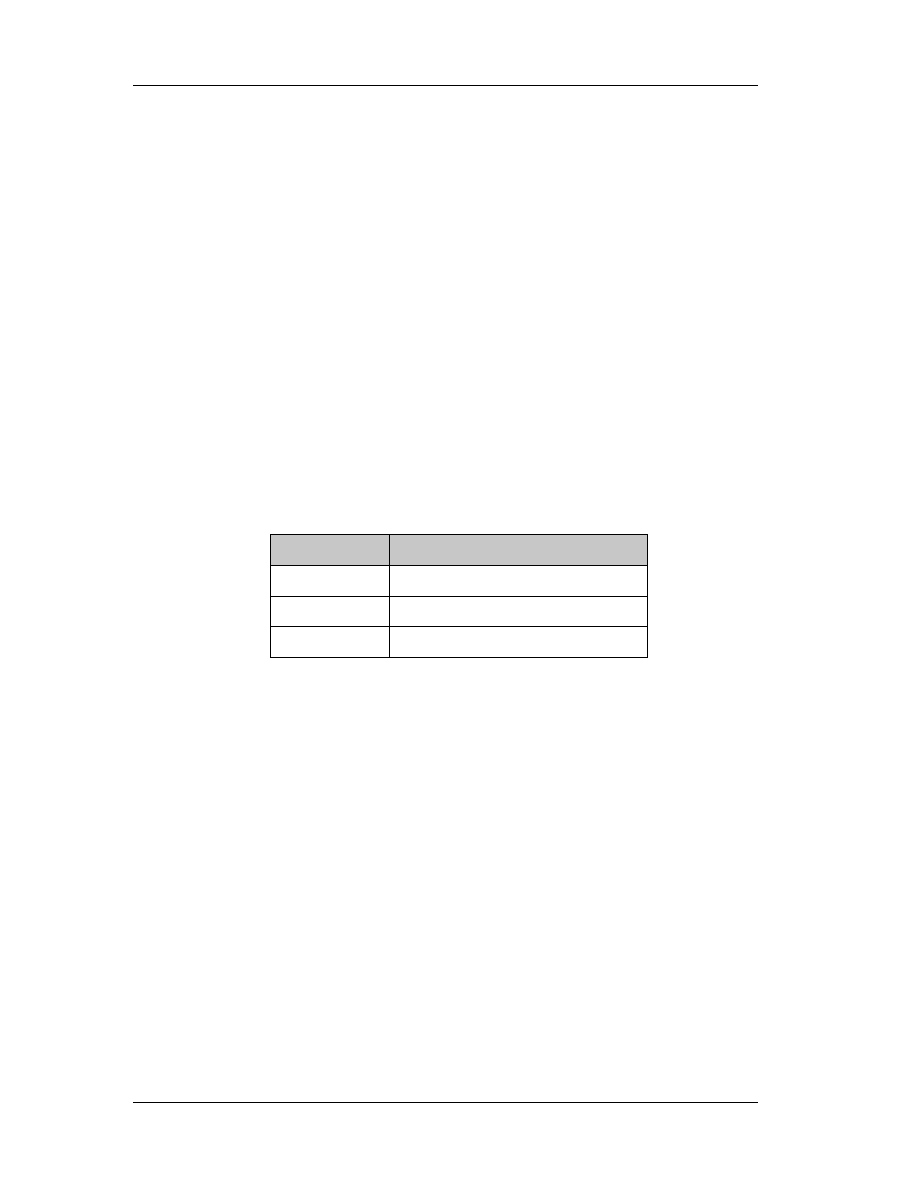
generations. Today, the most popular generation is the third. The following table
summarizes some of the various existing languages. (Machine code is zero generation
language, since it is not a language!)
Table 1: Various Language split according to their generation status.
Generation
Language
First Assembly
Second
Fortran, C, Basic, Pascal, Cobol
Third
Visual C++, Visual Basic, Delphi
To distinguish second and third generation languages, one can think of various
ways. The common element between third generation languages is that they support
Object Oriented Programming (OOP) and the usage of objects. This makes them
extremely flexible and powerful, thus enabling programmers to create applications with
an attractive graphic interface quickly and easily.
It can be said that according to table 1, assembly is a primitive language,
therefore almost obsolete. That is not true. Assembly will exist as long as processors
exist. It allows direct communication with the processor, which in turn allows direct
communication with all peripherals. Imagine that we make a program in Fortran. When
we finish composing the source code, we have to compile it, in other words to create an
executable, so that the operating system can execute our program.

Chapter 2: Computer Architecture
17
The
compiler is the external program, which translates our comprehensive
source code, written in any language (2
nd
or 3
rd
generation) into machine code. Each
language uses (obviously) a different compiler, but all programs eventually are
converted into executable files.
No matter which language is being used to create a program, we can always
disassemble the executable file, i.e. convert the executable code into comprehensive
assembly code. The only problem is that assembly is a rather difficult language and
processor dependent; therefore we need to learn many processor specific instructions
and, of course, become familiar with the concepts of the assembly programming
language. In general, this is very difficult and requires a lot of time and practice.
However, it is very easy to learn how to “read” certain parts of a disassembled code and
extract the information needed, then convert it into another language (or leave it as
assembly code).
The only exceptions to the above rules are Java (we can get the source code in
Java) and Visual Basic versions 2 and 3 (which had the source code stored in the
executable file, hence the extraction was a simple task).
Table 2 lists some of the programming languages in ascending order regarding
the statements needed per function point. Nowadays, there is a tendency of creating
languages that do many functions in the background and facilitate the programmer.
Languages with more statements per function point are more difficult to learn and use..
Note the places of C++ and Visual Basic.
So, if a particular program is to be created using assembly, we’ll need 53 times
more statements per function point than creating this program in VBA. The only
question now is, can we do everything with VBA? It would be foolish if someone
interested in creating a graph used assembly of fortran77. However, if you intend to
directly access and change the memory location of a variable, then you just can’t do it
with any other programming language but assembly.
Chapter 2: Computer Architecture
18
Table 2: Number of statements per function point for several languages.
Language
Statements per function point
Assembly 320
C 125
Fortran77 110
Cobol 90
Smalltalk 80
Lisp 65
C++ 50
Oracle (databases) 40
Visual Basic
30
Perl 25
VBA 6
2.2 Processor Arithmetic
The only thing that a computer processor can understand is the switch. And we
are talking about the simplest type of a switch, with just two positions: on and off.
When the switch is set to on (or true) we have the value 1. Otherwise, the switch is set
to the off position (or false) and we get the value 0.
This notation is great since it’s so easy to understand. But it introduces some not
so obvious problems. Let’s see how computer understands our numbers. Since it has
only two symbols (1 and 0) to represent everything, we can’t use another number
system other than the binary. So, to convert a number from binary to decimal, we have
to do the following:
01101=0x2
4
+1x2
3
+1x2
2
+0x2
1
+1x2
0
= 13.
Note that the exponent starts counting from 0 from right to left and increases in
steps of 1 for every digit. This can be extent for virtually any number of digits.

Chapter 2: Computer Architecture
19
Each of the switches is a bit. So, it’s easy to understand what 16-bit or 32-bit is.
For 16-bit operating systems (such as windows 3.11) the largest number that we can
have is a 16 digit number with all its digits set to 1 which is 65535. Even for 32-bit
operating systems (windows 9x, NT, 2000, Me) the largest number is (signed)
2147483647, which is still too small.
The trick is to use an exponent. For numbers greater than 2.14 billion i.e.
10x200, the processor uses the number 200 which occupies 8 bits and the other 8 bits
are used for the rest of the number. The same trick is used to represent real numbers
(with a floating point).
" 21.4 can be written as .21400 002, where the last three digits are the exponent
of 10. .214x10
2
=21.4
" 5.5x10
199
can be written as .55000 200 (note that the floating point is not used,
since the first digit is considered to be 0 -> 0.55000 200 so we can safely
remove 0. from each of these numbers).
This notation does not directly apply to computers, since as we said before,
computers understand only 0 and 1. So, in order to force a processor understand the
number 0.3 we have to declare it as a division:
"
...
010891
.
0
1010
0000
0011
0000
10
3
3
.
0
>
−
=
=
and the processor is unable to compute
an equivalent to 0.3!
" for
011
.
0
1000
0000
0011
0000
8
3
375
.
0
>
−
=
=
, there is no problem.
The result of this notation, is that PC can’t perform accurately even the easiest
additions! Consider the following:

Chapter 2: Computer Architecture
20
Basic Listing
Dim i
Dim Sum
For i=1 to 100
Sum=Sum+1
Next i
C/C++ Listing
Int main()
{
int
i;
double
sum;
for
(i=1;i<100;i++)
sum=sum+1;
return
0;
}
Fortran Listing
DO 50 I=1,100,1
SUM=SUM+1
50 CONTINUE
No matter which programming language is used, the result is the same: not
100!! In fact, it’ll be a number very close to 100, like 99.99999283 and if we round the
number (we expect an integer) we get 100.
It is very difficult for humans to use another numbering system other than
decimal. However, there is one more system, the hexadecimal, which is very useful,
since it is divided by 8. The number 8 is the magic PC number. The bits are divided by 8
(8, 16, 32 and 64). The different numbers that can be represented by an 8-bit number
are 256 (divided by 8), with 16 bit, 65536 (again divided by 8), etc.

Chapter 2: Computer Architecture
21
The
hexadecimal numbering system has 16 symbols, from 0 to 9 and from A to
F. A is equal to 10, B to 11 and F to 15. Therefore, the number:
98DC in decimal is 9x16
3
+8x16
2
+13x16
1
+12x16
0
=39132
Hexadecimal numbers are represented usually by an ampersand in front of them
(Basic) or by the 0x symbol (C/C++):
0x18 is a hexadecimal number equal to 1x16+18=24 while
18 is a decimal number equal to 0x12.
Table 3: Hexadecimal to decimal and vice versa from 0 to 255.
0
1
2
3
4
5
6
7
8
9
A
B
C
F
E
F
0
0 1 2 3 4 5 6 7 8 9 19 11 12 13 14 15
1
16 17 18 19 20 21 22 23 24 25 26 27 28 29 30 31
2
32 33 34 35 36 37 38 39 40 41 42 43 44 45 46 47
3
48 49 50 51 52 53 54 55 56 57 58 59 60 61 62 63
4
64 65 66 67 68 69 70 71 72 73 74 75 76 77 78 79
5
80 81 82 83 84 85 86 87 88 89 90 91 92 93 94 95
6
96 97 98 99 100 101 102 103 104 105 106 107 108 109 110 111
7
112 113 114 115 116 117 118 119 120 121 122 123 124 125 126 127
8
128 129 130 131 132 133 134 135 136 137 138 139 140 141 142 143
9
144 145 146 147 148 149 150 151 152 153 154 155 156 157 158 159
A
160 161 162 163 164 165 166 167 168 169 170 171 172 173 174 175
B
176 177 178 179 180 181 182 183 184 185 186 187 188 189 190 191
C
192 193 194 195 196 197 198 199 200 201 202 203 204 205 206 207
D
208 209 210 211 212 213 214 215 216 217 218 219 220 221 222 223
E
224 225 226 227 228 229 230 231 232 233 234 235 236 237 238 239
F
240 241 242 243 244 245 246 247 248 249 250 251 252 253 254 255
Ex: 0xD6=214 and 102=0x66

Chapter 2: Computer Architecture
22
2.3 Memory Structure
It is very essential that the concept of memory is understood at this particular
point. There are three types of computer memory: the temporary physical (also known
as RAM), the temporary virtual (the virtual memory page file) and the permanent
physical (or storage – Hard disk drive).
So a processor can access its available temporary or permanent memory each
time an instruction is executed. Hard disk drive can be considered as a huge RAM that is
permanent, in terms of not getting wiped out when the system is reset. However the
contents that are stored can be altered or wiped out without restrictions of any kind. In
addition to this, modern motherboards come with EEPROM chipsets that provided ROM
to the user. In these chips, the BIOS program is stored. Of course, EEPROM’s contents
can be changed sometimes (with some special instructions) and that makes them
behave more than storage rather than physical memory unit.
Each time an application is loaded, it occupies some space in the available
memory. If there is not enough available memory, then the application cannot be
loaded. With the term application, we refer to any executable program (from the
operating system to the device drivers). What may cause some confusion is the term
“memory”. Why shouldn’t consider only the physical memory (usually 64 or 128 MB) as
the only available memory source. Windows (and the other operating systems) have
invented tricks to significantly increase the available physical memory, by taking
advantage of some free hard disk space.
This is done via the virtual memory system. A file is created, named
WIN386.SWP (which usually resides in the root directory) and is used as an extension to
the existing physical memory. Physical memory can be considered as a hard disk with
super fast access, where the OS can store and access variables and code. Therefore,
when our physical memory is full and the OS uses the hard disk drive, we can
experience delays in program execution (hard disk drive is much slower than the

Chapter 2: Computer Architecture
23
physical memory) and hard disk activity without doing anything (some processes are
active in the background even if we are not using our computer).
TIP: It is possible to determine the size of the available virtual memory through
the control panel. Setting it 2.5 times the available physical and fixed to that size will
increase our computer’s performance.
2.3.1 Variables
The operating system and the applications use internally and between them,
variables. These variables differ in content and type. They can be numbers (single,
integer, double, float, etc), strings (single characters, long strings), Booleans and user-
defined types. The point is that they contain different (in general) values and refer to
different things.
These variables are stored in memory that is allocated to an application.
Windows allocate 2 GB memory to any application. There is no erratum here; it’s 2 GB
although no application occupies that much space. The operating system automatically
allocates enough space for these variables and is able to relocate them on demand. For
example, an integer occupies 4 bytes while a long occupies 8 bytes and a char only 1.
We are particularly interested in variables, since all operations involve the usage
of variables. In assembly, registers are used instead of variables; the logic remains
however the same. Imagine the comparison routine. In most programming languages it
is a statement like this:
[C++] IF (A==B) <do something>
else <do something else>
[Basic] IF A=B then <do something> else <do something else>

Chapter 2: Computer Architecture
24
In the above examples, A and B are variables. They may or may not be of the
same type. Each language defines acceptable operations (i.e. compare integer with
long).
2.3.2 Unicode Strings
In Win32 systems, strings (for reasons that are out of the course’s scope) have
changed internal format. With the term “internal format”, we refer to the way the
Operating System handles them. Throughout these notes, we’ll be dealing with Unicode
strings unless specifically told otherwise.
All ASCII searches for strings should be made with Unicode search option turned
on in the hex editor (when this is available). The difference between ANSI and Unicode
strings is that a null character (00) is inserted after each character. Therefore the string
“ABC”, which in hex is “585960”, will be treated as “580059006000”.
2.3.3 Pointers
If we define a variable A and we assign the value 5 to it, then we can be sure
that each time we ask about the value of this variable, this will be 5, unless we change
it. What we can’t be sure of is the memory location of this variable. Take for example
this piece of memory:
##################****##############################
^ ^ ^ ^ ^
0x4990 0x49A0 0x49B0 0x49C0 0x49D0
If we assume that the variable A is an integer, we can be sure that it’ll occupy 4
bytes in the physical memory (RAM or virtual memory). Suppose that we could “see”
(yes, it is possible) when in memory this variable resides. If we have 128 MB of Ram
and variable A is somewhere in there, we can have a row of # as illustrated above,

Chapter 2: Computer Architecture
25
where each # would represent a byte. At the address 0x49A4 is where we find the
variable the first time we attempt to search for it.
Now, if we terminate the program, run it again and set the variable A equal to 5
as we did before and seek its location inside the physical memory, we’ll discover that the
location is completely different! The operating system obviously has used this location,
which was free after the termination of the program, for another purpose and now it has
allocated another memory space for our application and for this variable!
Why do we need to know the location in memory of a variable any time we run a
program? Because, this way it is possible to overwrite this value we something else on
the fly! Imagine playing Quake II. You are losing, since the available energy is 12. There
is a variable that holds the energy. If you could only find that location where 12 is, you
can switch to your debugger (Quake II stalls) and change this value to 150, then go
back in the arena and kill ’em all!
We use pointers to retrieve the location in memory of a variable. Pointers exist in
all major programming languages, either documented or undocumented. In C++ we use
funny symbols like & in front of a variable to get its address. In Visual Basic we use the
undocumented function VarPtr to get the pointer of a variable.

Chapter 3: Windows Anatomy
26
Chapter 3
3. Windows Anatomy
3.1 Windows API
Windows are revolutionary in personal computers. They brought multitasking and
multiprocessing in our personal computers. We are now able to surf the Internet, listen
to MP3 and use a word processor at the same time! Before this, there was the dark age
of DOS (Disk Operating System), which was single tasking. One could run only one
program at the time (ok, there were some TSR programs, but that’s another story). So if
you wanted to play a game and then write a document, you should terminate the game
and run the word processor. There were many limitations of course in the hardware
devices that were supported, Internet capabilities, available memory to programs, etc.
Windows brought the user close to the PC. And they did this by introducing an
open architecture to the developers. Windows programmers have now common
guidelines on how to create their programs. In DOS, each program had (if it had) a
different user interface. Some used mouse, some didn’t. Anyway, the similarities were
few if any. Now with windows, no matter what application we are using, we expect
certain features to exist and behave as expected. Consider the caption bar of any
window, the click buttons, the check boxes etc.
Therefore, the user can easily control any windows application. But how is it
possible that a programmer can use the same type of buttons (sometimes with slight
variations)? Windows come with the API (Application Programming Interface), which
consists of hundreds of functions, available to any windows program. Most of the API
functions are coded in DLL (Dynamic Link Libraries) and the programmer can use them
if he links his program to these DLLs.

Chapter 3: Windows Anatomy
27
The only problem is that, API changes since Windows change. New functions are
introduced, bugs are fixed, old function become obsolete. For that reason, a program
that worked well with Windows 95, may not work well or at all with Windows ME. API
changes are available in three ways:
" Windows upgrades (i.e. Win 95 to Win 2000)
" Windows updates (i.e. Win 95 to Win 95b)
" Service packs (i.e. Win 2000 to Win 2000 sp1)
Detailed information about the API can be found in Microsoft Platform SDK web site
(
http://www.microsoft.com/msdownload/platformsdk/setuplauncher.asp
). There you can
download for free and use the latest edition of the platform SDK which includes detailed
description of all the documented API functions (there are also undocumented API
functions, reserved for Microsoft’s reference only %)
Why are we interested in Windows API? Because all programs use some
functions of the windows API. Each time a button is clicked, text is retrieved from a text
box or a window is moved, a certain API function is executed. With the debugger we
can set trap and intercept program’s execution that lies between these functions, as
we’ll see later.
3.2 File System
In the beginning there was FAT (also known as FAT16). FAT was the file system
used by DOS, Windows 3.x and Windows 95 first edition. Windows 95 second edition,
Windows 98 and Windows 2000 can use FAT32 and FAT16. Windows NT4 and Windows
2000 can use NTFS (NT File System).
FAT stands for File Allocation Table. It resides in the hard disk and contains
information that is used by the operating system to determine where in the hard disk is
a particular file. A file can start at a location, then be interrupted and restart at another

Chapter 3: Windows Anatomy
28
location. A file like this is fragmented and when we defragment the hard disk, we join all
the pieces of fragmented files like this.
To access (read or write) the hard drive (or the floppy disk, CD-Rom, DVD), a
programmer has to resolve to windows API and perform this access via the operating
system. However, certain operations (formatting illegally sectors, unmarking bad
clusters, etc) require direct access. This is rather simple with assembly, under Win9x
and Windows ME, VWIN32.VXD driver must be used or the equivalent direct access API
under Windows NT and Windows 2000.
3.3 File Anatomy
Each file, no matter its contents, has a purpose. It may be an executable file, a
media file (image, cursor, icon, sound, midi, etc), a text file, an application specific file
(like Corel Draw file, Excel document, Powerpoint Presentation, etc) or anything else the
user and programmer may want and need.
It is important and necessary that the Operating System is aware with which
application it should process a certain file. The concept of file extensions (the part of the
filename which comes after the fullstop) has been created to assist the OS and the users
to identify a file. Consider the filename “mykids.jpg”. The extension jpg informs us that
we should expect a JPEG image file, which should be processed by an image
viewer/editor.
What happens if we change this extension from jpg to bmp? Sure they are both
image files, but the operating system will *think* that this is a jpg file. It’s up to the
application to understand that this file is not a bitmap, but a JPEG. Also, consider the
following: the two files logo.sys, logos.sys and logow.sys are image files (the startup
and shutdown logo screens in windows) and have the same extension with msdos.sys
which is a text file. Still clever programs like ACDSee can identify that logo.sys is an
image file, while msdos.sys is not. So there has to be something more.

Chapter 3: Windows Anatomy
29
Most of the files come with a header (apart from plain ASCII files). The header is
a small part that resides in the beginning of the file and contains information regarding
its contents. For example, every executable starts with MZ (Old DOS format) and
contains a small loader that can operate in DOS. Thus, if we try to execute a windows
file under DOS, an error message will appear, indicating “This program cannot be run in
DOS mode” and inform the user that he should run the program in Windows.
3.3.1 File Header
The format of an operating system's executable file is in many ways a mirror of
the operating system s built-in assumptions and behaviors. Although studying the ins
and outs of an executable file format isn't something that usually appears high on most
programmers' list of things to do, a great deal of useful knowledge about the operating
system can be gleaned from doing this. Dynamic linking, loader behavior, and memory
management are just three examples of operating system specifics that can be inferred
by studying the executable format.
To understand how the Windows 9x, NT, 2000 or ME kernel works, you need to
understand the PE format: It's that simple. And of course we do need to understand
these kernels since we are going to be involved in reversing them!
It's common knowledge that Windows NT (the first of the Win32 operating
systems) has a VAX VMS and UNIX heritage. Many of the key NT developers designed
and coded for those platforms before coming to Microsoft. When it came time to design
NT, it was only natural that they tried to minimize their bootstrap time by using
previously written and tested tools. The executable and object module format that these
tools produced and worked with is called COFF (Common Object File Format).
The relatively old (in computer years) nature of COFF can be seen in the fact
that certain fields in the files are specified in octal format. The COFF format by itself was
a good starting point, but needed to be extended to meet all the needs of a modern
operating system such as Windows NT or Windows 95. The result of this updating is the

Chapter 3: Windows Anatomy
30
PE (remember, this stands for Portable Executable) format. It's called portable
because
all the implementations of NT on various platforms (Intel 386, MIPS, Alpha, Power PC,
and so on) use the same executable format. Sure, there are differences in things such
as the binary encoding of CPU instructions. You can't run a MIPS compiled PE
executable on an Intel system. However, the important thing is that the operating
system loader and programming tools don't have to be completely rewritten for each
new CPU that arrives on the scene.
The strength of Microsoft's commitment to get Windows NT up and running
quickly is evidenced by the fact that it abandoned existing Microsoft 32-bit tools and file
formats. Virtual device drivers written for Windows 3.x were using a different 32-bit file
layout (the LE format) long before NT appeared on the scene. In a testimonial to the "if
it ain't broke, don't fix it" nature of Windows, Windows 95 uses both the PE format and
the LE format. This allowed Microsoft to use existing Windows 3.x code in a big way.
Although it's reasonable to expect a completely new operating system (Windows
NT, that is) to have a completely different executable format, it's a different story when
it comes to object module (.OBJ and LIB) formats. Before Visual C++ 32-bit edition 1.0,
all Microsoft compilers used the Intel OMF (Object Module Format) specification. The
Microsoft compilers for Win32 implementations produce COFF format OBJ files. Some
Microsoft competitors such as Borland have chosen to forego the COFF format OBJs and
stick with the Intel OMF format. The result of this is that companies producing OBJs or
LIBs for use with multiple compilers will need to go back to distributing separate
versions of their products for different compilers (if they weren't already).
Those of you who like to read conspiracy into Microsoft's actions might see the
decision to change OBJ formats as evidence of Microsoft trying to hinder its competitors.
To claim true Microsoft "compatibility" down to the OBJ level, other vendors will need to
convert all their 32-bit tools over to the COFF OBJ and LIB formats. In short, the OBJ
and LIB file format can be viewed as yet another example of Microsoft abandoning
existing standards in favor of something that suits it better.

Chapter 3: Windows Anatomy
31
3.3.2 Into PE Format
The PE format is documented (in the loosest sense of the word) in the WINNT. H
header file, along with certain structure definitions for COFF format OBJs. (I'll be using
the field names from WINNT. H later in the chapter.) About midway through WINNT.H is
a section titled "Image Format." This section of the file starts out with small tidbits from
the old familiar DOS MZ format and NE format headers before moving into the newer PE
information. WINNT. H provides definitions of the raw data structures used by PE files,
but contains only the barest hint of useful comments to explain what the structures and
flags mean. The author of the header file for the PE format is certainly a believer in
long, descriptive names, along with deeply nested structures and macros. When coding
with WINNT. H, it's not uncommon to have expressions like this:
pNTHeader->OptionalHeader.DataDirectory[IMAGE_DIRECTORY_ENTRY_DEBUG].VirtualAddress;
Besides just reading about what PE files are composed of, you'll also want to
dump out some PE files to see for yourself the concepts presented here. If you use
Microsoft tools for Win32 development, the DUMPBIN program from Visual C++ and the
Win32 SDK can dissect and output PE files and COFF OBJ/LIB files in human-readable
form. DUMPBIN even has a nifty option to disassemble the code sections in the file it's
taking apart. In light of Microsoft's claims that you're not allowed to disassemble its
products, it's pretty interesting that it would provide a tool that makes it so easy to
disassemble its programs and DLLs. If the ability to disassemble EXEs and OBJs wasn't
useful, why would Microsoft have bothered to add this feature to DUMPBIN? It sure
sounds like another case of "Do as we say, not as we do."
We'll use the term module to mean the code, data, and resources of an
executable file or DLL that has been loaded into memory. Besides code and data that
your program uses directly, a module is also composed of the supporting data used by
Windows to determine where the code and data is located in memory.

Chapter 3: Windows Anatomy
32
In Win16, the supporting data structures are in the module database (the
segment referred to by an HMODULE). In Win32, this information is kept in the PE
header (the IMAGE_NT_HEADERS structure), which we'll explain in detail shortly.
The most important thing to know about PE files is that the executable file on
disk is very similar to what the module will look like after Windows has loaded it. That's
because the Windows loader doesn't need to work extremely hard to create a process
from the disk file. Rather, the loader can take it easy and use Win32 memory mapped
files to load the appropriate pieces of the PE file into a program's address space. To use
a construction analogy, a PE file is like a prefabricated house: There are relatively few
pieces, and each piece can be snapped into place with just a small amount of work.
And, just as it's fairly easy to hook up the electricity and water connections in a prefab
house, it's also a simple matter to wire a PE file up to the rest of the world (that is,
connect it to its DLLs, and so on).
This same ease of loading applies to DLLs as well. Once an .EXE or .DLL module
has been loaded, Windows can effectively treat it like any other memory-mapped file.
This is in marked contrast to the situation in 16-bit Windows. The 16-bit NE file loader
reads in portions of the file and creates separate data structures to represent the
module in memory. When a code or data segment needs to be loaded, the loader has to
allocate a new segment from the global heap, find where the raw data is stored in the
executable file, seek to that location, read in the raw data, and apply any applicable fix-
ups. In addition, each 16-bit module is responsible for remembering all the selectors it's
currently using, whether the segment has been discarded, and so on.
For Win32, however, all the memory used by the module for code, data,
resources, import tables, export tables, and other things is in one contiguous range of
linear address space. All you need to know in this situation is the address where the
loader mapped the executable file into memory. You can then easily find all the various
pieces of the module by following pointers stored as part of the image.

Chapter 3: Windows Anatomy
33
Another idea you should be acquainted with before we start is the Relative
Virtual Address, or RVA. Many fields in PE files are specified in terms of RVAs. An RVA is
simply the offset of some item, relative to where the file is memory mapped to. For
example, let's say the Windows loader mapped a PE file into memory starting at address
0x400000 in the virtual address space. If a certain table in the image starts at address
0x401464, the table's RVA is 0x1464:
(virtual address 0x401464)- (base address 0x400000) = RVA 0x1464
To convert an RVA into a usable pointer to memory, simply add the RVA to the
base address where the module was loaded into. The term base address is another
important concept to remember. A base address describes the starting address of a
memory mapped EXE or DLL. For convenience, Windows NT and Windows 95 use the
base address of a module as the module's instance handle (HINSTANCE). In Win32,
calling the base address of a module an HINSTANCE is somewhat confusing, because
the term instance handle comes from 16-bit Windows.
Each copy of an application in Winl6 gets its own separate data segment (and an
associated global handle) that distinguishes it from other copies of the application;
hence the term, instance handle. In Win32, applications don't need to be distinguished
from one another because they don't share the same address space. Still, the term
HINSTANCE persists to keep at least the appearance of continuity between Winl6 and
Win32. What's important for Win32 is that you can call GetModuleHandle() for any DLL
that your process uses, and get a pointer that you can use to access the module's
components. By components, we refer to its imported and exported functions, its
relocations, its code and data sections, and so on.
Another concept to be familiar with when investigating PE files and COFF OBJs is
the section. A section in a PE file or COFF OBJ file is roughly equivalent to a segment or
the resources in a 16-bit NE file. Sections contain either code or data. Some sections
contain code or data that your program declared and uses directly, while other data
sections are created for you by the linker and librarian, and contain information vital to
Chapter 3: Windows Anatomy
34
the operating system. In some of Microsoft's descriptions of the PE format, sections are
also referred to as objects. This term has so many possibly conflicting meanings,
however, that I'll stick to calling the code and data areas sections.
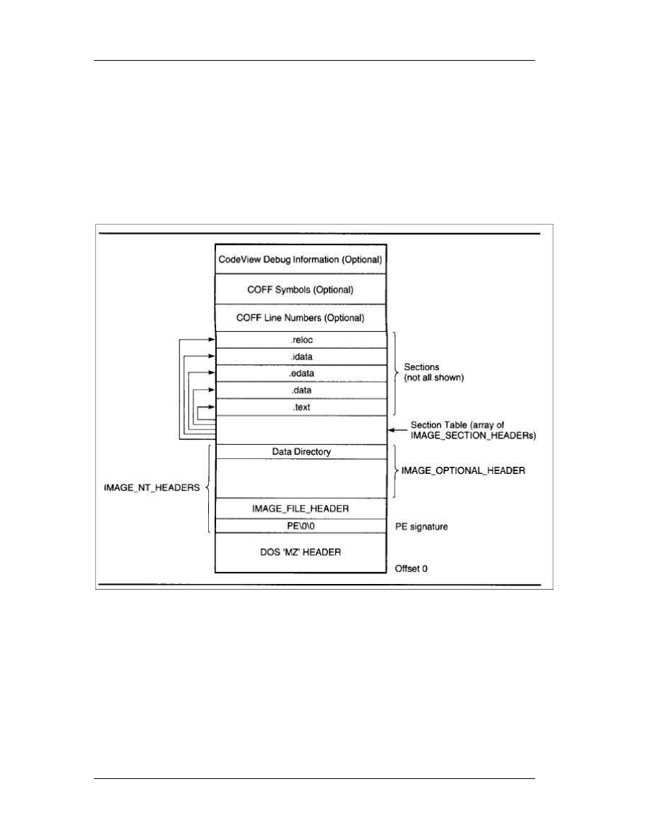
Before jumping into the details of the PE file, examine the figure below, which
shows the overall layout of a PE file.
3.3.3 The PE Header
The first stop on our tour of the PE format is the PE header. Like all other
Microsoft executable file formats, the PE file has a collection of fields at a known (or
easy-to-find) location that define what the rest of the file looks like. The PE header
contains vital pieces of information such as the location and size of the code and data

Chapter 3: Windows Anatomy
35
areas, what operating system the file is intended to be used with, and the initial stack
size.
As with other executable formats from Microsoft, the PE header isn't at the very
beginning of the file. Instead, the first few hundred bytes of the typical PE file are taken
up by the DOS stub. This stub is a minimal DOS program that prints out something to
the effect of "This program cannot be run in DOS mode." The intent is that if you run a
Win32 program in an environment that doesn't support Win32, you'll get an informative
(and frustrating) error message. When the Win32 loader memory maps a PE file, the
first byte of the file mapping corresponds to the first byte of the DOS stub. That's right.
With every Win32 program you start up, you get a complimentary DOS program loaded
for free! (In Win16, the DOS stub isn't loaded into memory.)
As in other Microsoft executable formats, you find the real header by looking up
its starting offset, which is stored in the DOS header. The WINNT.H file includes a
structure definition for the DOS stub header that makes it very easy to look up where
the PE header starts. The e_lfanew field is a relative offset (or RVA, if you prefer) to the
actual PE header. To get a pointer to the PE header in memory, just add the field's value
to the image base:
// Ignoring typecasts and pointer conversions for clarity...
pNTHeader = dosHeader + dosHeader->e_lfanew;
Once you have a pointer to the main PE header, the real fun begins. The main
PE header is a structure of type IMAGE_NT_HEADERS, defined in WINNT. H. The
IMAGE_NT_HEADERS structure in memory is what Windows 95 uses as its in-memory
module database. Each loaded EXE or DLL in Windows 95 is represented by an
IMAGE_NT_HEADERS structure. This structure is composed of a DWORD and two
substructures, and is laid out as follows:
DWORD Signature;
IMAGE_FILE_HEADER FileHeader;
IMAGE_OPTIONAL_HEADER OptionalHeader;

Chapter 3: Windows Anatomy
36
The Signature field viewed as ASCII text is PE\0\0 (PE followed by two 0 bytes).
If the e_lfanew field in the DOS header pointed to an NE signature at this location
instead of a PE signature, you'd be working with a Win16 NE file. Likewise, an LE in the
signature field would indicate a Virtual Device Driver (VxD) file. An LX here would be the
mark of a file for Windows 95's arch rival, OS/2.
3.3.3.1 Image File Header
Following the PE signature DWORD in the PE header is a structure of type
IMAGE_FILE_HEADER. The fields of this structure contain only the most basic
information about the file. The structure appears to be unmodified from its original COFF
implementations. Besides being part of the PE header, it also appears at the very
beginning of the COFF OBJs produced by the Microsoft Win32 compilers. The fields of
the IMAGE_FILE_HEADER follow.
WORD Machine
The CPU that this file is intended for. The following CPU IDs are defined:
CPU
Code
Intel I386
0x14C
Intel i860
0x14D
MIPS R3000
0x162
MIPS R4000
0x166
DEC Alpha AXP
0x184
Power PC
0x1F0 (little endian)
Motorola 68000 0x268
PA RISC
0x290
WORD NumberOfSections
The number of sections included in the EXE or OBJ.
Chapter 3: Windows Anatomy
37
DWORD TimeDateStamp
The time and date that the linker (or compiler for an OBJ file) produced this file.
This field holds the number of seconds since December 31, 1969, at 4:00 P.M.
DWORD PointerToSymbolTable
The file offset of the COFF symbol table. This field is used only in OBJ files and
PE files with COFF debug information. PE files support multiple debug formats, so
debuggers should refer to the IMAGE_DIRECTORY_ENTRY_DEBUG entry in the data
directory (defined later).
DWORD NumberOfSymbols
The number of symbols in the COFF symbol table. See the preceding field.
WORD SizeOfOptionalHeader
The size of an optional header that can follow this structure. In executables, it is
the size of the IMAGE_OPTIONAL_HEADER structure that follows this structure. In OBJs,
Microsoft says this field is supposed to always be 0. However, in dumping out the
KERNEL32.LIB import library, there's an OBJ in there with a nonzero value in this field,
so take their advice with a grain of salt.
WORD Characteristics
Flags that contain useful information about the file. Some important fields are
described here (other fields are defined in WINNT. H):
Flag
Comment
0x0001 There are no relocations in this file.
0x0002 File is an executable image (that is, not a OBJ or LIB).
0x2000 File is a dynamic link library, not a program.
Chapter 3: Windows Anatomy
38
3.3.3.2 Image Optional Header
The third component of the PE header is a structure of type
IMAGE_OPTIONAL_HEADER. For PE files, this portion certainly isn't optional. The COFF
format allows individual implementations to define a structure of additional information
beyond the standard IMAGE_FILE_HEADER. The fields in the
IMAGE_OPTIONAL_HEADER are what the PE designers felt was critical information
beyond the basic information in the IMAGE_FILE_HEADER.
All the fields of the IMAGE_OPTIONAL_HEADERS aren't necessarily critical for
you to know. The more important ones are the ImageBase and the Subsystem fields. If
you want, you can skim over or skip the following description of the fields.
WORD Magic
A signature WORD that identifies the state of the image file. The following values
are defined:
Flag
Desciption
0x0107
A ROM Image
0x010B A normal executable file (most files contain this value)
BYTE MajorL ink erVersion
BYTE MinorLinkerVersion
The version of the linker that produced this file. The numbers should be
displayed as decimal values, rather than as hex. A typical linker version is 2.23.
DWORD SizeOfCode
The combined and rounded-up size of all the code sections. Usually, most files
have only one code section, so this field typically matches the size of the .text section.

Chapter 3: Windows Anatomy
39
DWORD SizeOfinitializedData
This is supposedly the total size of all the sections that are composed of
initialized data (not including code segments.) However, it doesn't seem to be consistent
with the size of the initialized data sections in the file.
DWORD SizeOfUninitializedData
The size of the sections that the loader commits space for in the virtual address
space, but that don't take up any space in the disk file. These sections don't need to
have specific values at program startup, hence the term uninitialized
data. Uninitialized
data usually goes into a section called.
DWORD AddressOfEntry
The address where the image begins execution. This is an RVA, and usually can
be found in the .text section. This field is valid for both EXEs and DLLs.
DWORD BaseOfCode
The RVA where the file's code sections begin. The code sections typically come
before the data sections, and after the PE header in memory. This RVA is usually 0x1000
in Microsoft Link produced EXEs. Borland's TLINK32 typically has a value of 0x10000 in
this field because it defaults to aligning objects on 64K boundaries, rather than 4K like
the Microsoft linker.
DWORD BaseOfData
The RVA where the file's data sections begin. The data sections typically come
last in memory, after the PE header and the code sections.
DWORD ImageBase
When the linker creates an executable, it assumes that the file will be memory
mapped to a specific location in memory. That address is stored in this field. Assuming a
load address allows linker optimizations to take place. If the file really is memory
mapped to that address by the loader, the code doesn't need any patching before it can

Chapter 3: Windows Anatomy
40
be run. I'll talk more about this in the discussion of the base relocations. In NT 3.1
executables, the default image base was 0x10000.
For DLLs, the default was 0x400000. In Windows 95, the address 0x10000 can't
be used to load 32-bit EXEs because it lies within a linear address region that's shared
by all processes. Therefore, in Windows NT 3.5, Microsoft changed the default base
address for Win32 Executables to 0x400000.
Older programs that were linked assuming a base address of 0x10000 will take
longer to load under Windows 95 because the loader needs to apply the base
relocations. I'll describe base relocations in detail later.
DWORD SectionAlignment
When mapped into memory, each section is guaranteed to start at a virtual
address that's a multiple of this value. For paging reasons, the minimum section
alignment is 0x1000, which is what the Microsoft linker uses by default. Borland C++'s
TLINK defaults to 0x10000 (64KB).
DWORD FileAlignment
In the PE file, the raw data that comprises each section is guaranteed to start at
a multiple of this value. The default value is 0x200 bytes, probably to ensure that
sections always start at the beginning of a disk sector (which are also 0x200 bytes in
length).
This field is equivalent to the segment/resource alignment size in NE files. Unlike
NE files, PE files typically don't have hundreds of sections, so the space wasted by
aligning the file sections is usually very small.
WORD Subsystem
The type of subsystem that this executable uses for its user interface. WINNT. H
defines the following values:
Chapter 3: Windows Anatomy
41
Subsystem
Value
Comment
Native
1
Doesn't require a subsystem (for example, a device driver)
Windows_GUI 2
Runs in the Windows GUI subsystem
Windows_GUI 3
Runs in Windows character subsystem (console application)
OS2_GUI
5
Runs in the OS/2 character subsystem (OS/2 1.x only)
POSIX_GUI
7
Runs in the Posix character subsystem
WORD DllCharacteristics (marked as obsolete in NT 3.5)
A set of flags indicating which circumstances a DLL's initialization function (for
example, DllMain()) will be called for. This value appears to always be set to 0, yet the
operating system still calls the DLL initialization function for all four events. The
following values are defined:
Value Explanation
1
Call when DLL is first loaded into a process's address space
2
Call when a thread terminates
4
Call when a thread starts up
8
Call when DLL exits
DWORD SizeOfStackReserve
The amount of virtual memory to reserve for the initial thread's stack. Not all of
this memory is committed, however (see the next field). This field defaults to 0x100000
(1MB). If you specify 0 as the stack size to CreateThread(), the resulting thread will also
have a stack of this same size.
DWORD SizeOfStackCommit
The amount of memory that's initially committed for the initial thread's stack.
This field defaults to 0x1000 bytes (1 page) in Microsoft Linkers, while TLINK32 sets it to
0x2000 bytes (2 pages).
Chapter 3: Windows Anatomy
42
DWORD SizeOfHeapReserve
The amount of virtual memory to reserve for the initial process heap. This heap's
handle can be obtained by calling GetProcessHeap(). Not all of this memory is
committed (see the next field).
DWORD SizeOfHeapCommit
The amount of memory initially committed in the process heap. The linker
defaults to putting 0x1000 bytes in this field.
DWORD LoaderFlags (marked as obsolete in NT 3.5)
From WINNT. H, these appear to be fields related to debugging support. I've
never seen an executable with either of these bits enabled, nor is it clear how to get the
linker to set them. The following values are defined:
Value Possible(!) Explanation
1
Invoke a breakpoint instruction before starting the process
2
Invoke a debugger on the process after it's been loaded
DWORD NumberOfRvaAndSizes
The number of entries in the DataDirectory array (see the following field
description). This value is always set to 16 by the current tools.
IMAGE_DATA_DIRECTORY DataDirectory[IMAGE_NUMBEROF_DIRECTORY_ENTRIES]
An array of IMAGEDATA_DIRECTORY structures. The initial array elements
contain the starting RVA and sizes of important portions of the executable file. Some
elements at the end of the array are currently unused. The first element of the array is
always the address and size of the exported function table (if present). The second
array entry is the address and size of the imported function table, and so on. For a
complete list of defined array entries, see the IMAGE_DIRECTORY_ENTRY_xxx #define's
in WINNT. H.

Chapter 3: Windows Anatomy
43
The intent of this array is to allow the loader to quickly find a particular section
of the image (for example, the imported function table), without needing to iterate
through each of the image's sections, comparing names as it goes along.
Most array entries describe an entire section's data. However, the
IMAGE_DIRECTORY_ENTRY_DEBUG element encompasses only a small portion of the
bytes in the .rdata section. There's more information on this in "The .rdata section"
portion of this chapter.
3.3.4 Section Table
Between the PE header and the raw data for the image's sections lies the section
table. The section table contains information about each section in the image. The
sections in the image are sorted by their starting address rather than alphabetically.
At this point, it would be worthwhile to clarify what a section is. In an NE file,
your program's code and data are stored in distinct segments in the file. Part of an NE
header is an array of structures, one for each segment your program uses. Each
structure in the array contains information about one segment. The stored information
includes the segment's type (code or data), its size, and its location elsewhere in the
file. In a PE file, the section table is analogous to the segment table in the NE file.
Unlike an NE file segment table though, a PE section table doesn't store a
selector value for each code or data chunk. Instead, each section table entry stores an
address where the file's raw data has been mapped into memory. Although sections are
analogous to 32-bit segments, they really aren't individual segments. Instead, a section
simply corresponds to a memory range in a process's virtual address space.
Another way in which PE files diverge from NE files is how they manage the
supporting data that your program doesn't use, but that the operating system does. Two
examples are the list of DLLs that the executable uses and the location of the fix-up
table. In an NE file, resources aren't considered to be segments.

Chapter 3: Windows Anatomy
44
Even though they have selectors assigned to them, information about resources
isn't stored in the NE header's segment table. Instead, resources are relegated to a
separate table toward the end of the NE header. Information about imported and
exported functions also doesn't warrant its own segment, but is instead crammed into
the confines of the NE header.
The story with PE files is different. Anything that might be considered vital code
or data is stored in a full-fledged section. Thus, information about imported functions is
stored in its own section, as is the table of functions that the module exports. The same
is true for the relocation data. Any code or data that might be needed by either the
program or the operating system gets its own section.
Immediately following the PE header in memory is an array of
IMAGE_SECTION_HEADERs. The number of elements in this array is given in the PE
header (the IMAGE NT HEADER.FileHeader.NumberOfSections field). The PEDUMP
program outputs the section table and all of the section's fields and attributes.
01 .text VirtSize: 00005AFA VirtAddr: 00001000
raw data offs: 00000400 raw data size: 00005C00
relocation offs: 00000000 relocations: 00000000
line # offs: 00009220 line #'s: 0000020C
characteristics: 60000020
CODE MEM_EXECUTE MEM_READ
02 .bss VirtSize: 00001438 VirtAddr: 00007000
raw data offs: 00000000 raw data size: 00001600
relocation offs: 00000000 relocations: 00000000
line # offs: 00000000 line #'s: 00000000
characteristics: C0000080
UNINITIALIZED_DATA MEM_READ MEM_WRITE
03 .rdata VirtSize: 0000015C VirtAddr: 00009000

Chapter 3: Windows Anatomy
45
raw data offs: 00006000 raw data size: 00000200
relocation offs: 00000000 relocations: 00000000
line # offs: 00000000 line #'s: 00000000
characteristics: 40000040
INITIALIZED_DATA MEM_READ
04 .data VirtSize: 0000239C VirtAddr: 0000A000
raw data offs: 00006200 raw data size: 00002400
relocation offs: 00000000 relocations: 00000000
line # offs: 00000000 line #'s: 00000000
characteristics: C0000048
INITIALIZED_DATA MEM_READ MEM_WRITE
05 .idata VirtSize: 0000033E VirtAddr: 0000D000
raw data offs: 00008600 raw data size: 00000400
relocation offs: 00000000 relocations: 00000000
line # offs: 00000000 line #'s: 00000000
characteristics: C0000040
INITIALIZED DATA MEN_READ MEM_WRITE
06 .reloc VirtSize: 000006CE VirtAddr: 0000E000
raw data offs: 00008A00 raw data size: 00000800
relocation offs: 00000000 relocations: 00000000
line # offs: 00000000 line #'s: 00000000
characteristics: 42000040
INITIALIZED DATA MEM_DISCARDABLE MEM_READ
07 .drectve PhysAddr: 00000000 VirtAddr: 00000000
raw data offs: 000000DC raw data size: 00000026
relocation offs: 00000000 relocations: 00000000
line # offs: 00000080 line #'s: 00000000
characteristics: 00100A00
LNK_INFO LNK_REMOVE
08 .debug$S PhysAddr: 00000026 VirtAddr: 00000000

Chapter 3: Windows Anatomy
46
raw data offs: 00000102 raw data size: 000016D0
relocation offs: 000017D2 relocations: 00000032
line # offs: 00000080 line #'s: 00000000
characteristics: 42100048
INITIALIZED_DATA MEM_DISCARDABLE MEM_READ
09 .data PhysAddr: 000016F6 VirtAddr: 00000000
raw data offs: 000019C6 raw data size: 00000D87
relocation offs: 0000274P relocations: 00000045
line # offs: 00000000 line #'s: 00000000
characteristics: C0480048
INITIALIZED_DATA MEM_READ MEM_WRITE
10 .text PhysAddr: 0000247D VirtAddr: 00000000
raw data offs: 000029FF raw data size: 000010DA
relocation offs: 00003AD9 relocations: 000000E9
line # offs: 000043F3 line #'s: 000000D9
characteristics: 60500020
CODE MEM_EXECUTE MEM_READ
85 .debug$T PhysAddr: 00003557 VirtAddr: 00000000
raw data offs: 00004909 raw data size: 00000030
relocation offs: 00000008 relocations: 00000000
line # offs: 00000000 line #'s: 00000000
characteristics: 42]00048
INITIALIZED_DATA MEM_DISCARDABLE MEM_READ
Each IMAGE_SECTION_HEADER is a complete database of information about one
section in the EXE or OBJ file, and has the following format:
BYTE Name[IMAGE_SIZEOF_SHORT_NAME]
This is an 8-byte ANSI name (not Unicode) that names the section. Most section
names start with a . (a period; for example, .text), but this is
not a requirement, in spite

Chapter 3: Windows Anatomy
47
of what some PE documentation would have you believe. You can name your own
sections with either the segment directive in assembly language, or with #pragma
data_seg and #pragma code_seg in the Microsoft C/C++ compiler. (Borland C++ users
should use #pragma codeseg.) It's important to note that if the section name takes up
the full 8 bytes, there is no NULL terminator byte. (TDUMP from Borland C++ 4.0x
overlooked this fact, and would spew forth garbage on certain PE EXEs.) If you're a
printf() devotee, you can use "%.8s" to avoid having to copy the name string to another
buffer to null terminate it.
union {
DWORD PhysicalAddress
DWORD VirtualSize
} Misc;
This field has different meanings, depending on whether it occurs in an EXE or
an OBJ. In an EXE, it holds the virtual size of the code or data section. This is the size
before rounding up to the nearest file-alignment multiple. The SizeOfRawData field later
on in the structure holds this rounded-up value. Interestingly, Borland's TLINK32
reverses the meaning of this field and the SizeOfRawData field, and appears to be the
correct linker. For OBJ files, this field indicates the physical address of the section. The
first section starts at address 0. To find the physical address of the next section, add the
SizeOfRawData value to the physical address of the current section.
DWORD VirtualAddress
In EXEs, this field holds the RVA for where the loader should map the section to.
To calculate the real starting address of a given section in memory, add the base
address of the image to the section's VirtualAddress stored in this field. With Microsoft
tools, the first section defaults to an RVA of 0xl000. In OBJs, this field is meaningless
and is set to 0.
DWORD SizeOfRawData
In EXEs, this field contains the size of the section after it's been rounded up to
the file-alignment size. For example, assume a file-alignment size of 0x200. If the

Chapter 3: Windows Anatomy
48
VirtualSize field says that the section is 0x35A bytes in length, this field will say that the
section is 0x400 bytes long. In OBJs, this field contains the exact size of the section
emitted by the compiler or assembler. In other words, for OBJs, it's equivalent to the
VirtualSize field in EXEs.
DWORD PointerToRawData
This is the file-based offset to where the raw data for the section can be found.
If you memory map a PE or COFF file yourself (rather than letting the operating system
load it), this field is more important than the VirtualAddress field. That's because in this
situation you'll have a completely linear mapping of the entire file, so you'll find the data
for the sections at this offset rather than at the RVA specified in the VirtualAddress field.
DWORD PointerToRelocations
In OBJs, this is the file-based offset to the relocation information for this section.
The relocation information for each OBJ section immediately follows the raw data for
that section. In EXEs, this field (and the subsequent field) are meaningless, and are set
to 0.
When the linker creates the EXE, it resolves most of the fix-ups, leaving only
base address relocations and imported functions to be resolved at load time. The
information about base relocations and imported functions is kept in the base relocation
and imported functions sections, so there's no need for an EXE to have per-section
relocation data following the raw section data.
DWORD PointerToLinenumbers
The file-based offset of the line number table. A line number table correlates
source-file line numbers to the addresses where the code generated for a given line can
be found. In modern debug formats like the CodeView format, line number information
is stored as part of the debug information. In the COFF debug format, however, the line
number information is conceptually distinct from the symbolic name/type information.
Usually, only code sections (for example, .text or CODE) have line numbers. In EXE files,

Chapter 3: Windows Anatomy
49
the line numbers are collected toward the end of the file, after the raw data for the
sections.
In OBJ files, the line number table for a section comes after the raw section data
and the relocation table for that section. I'll discuss the format of line number tables in
"The COFF Debug Information" section later in the chapter.
WORD NumberOfRelocations
The number of relocations in the relocation table for this section (the
PointerToRelocations field listed previously). This field appears to be used only in OBJ
files.
WORD NumberOfLinenumbers
The number of line numbers in the line number table for this section (the
PointerToLinenumbers field listed previously).
DWORD Characteristics
What most programmers call
flags, the COFF/PE format refers to as
characteristics. This field is a set of flags that indicate the section's attributes
(code/data, readable, writeable, and so on). For a complete list of all possible section
attributes, see the IMAGE_SCN_XXX XXX #defines in WINNT. H.
Flag Usage
It's interesting to note what's missing from the information stored for each
section. First, notice there's no indication of any PRELOAD attributes. The NE file format
lets you specify a PRELOAD attribute for segments that should be loaded immediately at
module load time. The OS/2 2.0 LX format has something similar, allowing you to
specify that up to 8 pages should be preloaded. The PE format, on the other hand, has
nothing like this. Based on this, we have to assume that Microsoft is confident in the
performance of the demand-paged loading of their Win32 implementations. Also missing
from the PE format is an intermediate page lookup table.

Chapter 3: Windows Anatomy
50
COFF flags
Explanation
0x00000020
Section contains code. Usually set in conjunction with the executable
flag.
0x00000040 This section contains initialized data. Almost all sections except
executable and the .bss section have this flag set.
0x00000080
This section contains uninitialized data (for example, the .bss section).
0x00000200 This section contains comments or some other type of information. A
typical use of this section is the .drectve section emitted by the compiler,
which contains commands for the linker.
0x00000800
This section's contents shouldn't be put in the final EXE file. This section
is used by the compiler/assembler lo pass information to the linker
0x02000000
This section can be discarded, since it's not needed by the process once
it's been loaded. The most common discardable section is the base
relocations section (.reloc).
0x10000000
This section is shareable. When used with a DLL, the data in this section
is shared among all processes using the DLL. The default is for data
sections to be nonshared, meaning that each process using a DLL gets
ils own separate copy of this section's data. In more technical terms, a
shared section tells the memory manager to set the page mappings for
this section so that all processes using the DLL refer to the same
physical page in memory. To make a section shareable, use the SHARED
attribute at link time. For example: LINK/SECTION:MYDATA, RWS ...
tells the linker that the section called MYDATA should be readable, write
able, and shared. By default, Borland C++ DLL data segments have the
shared attribute.
0x20000000
This section is executable. This flag is usually set whenever the Contains
Code flag (0x00000020) is set.
0x40000000 This section is readable. This flag is almost always set for sections in
EXE flies.
0x80000000 The section is writeable. If this flag isn't set in an EXE's section, the
loader should mark the memory-mapped pages as read-only or execute-
only. Typical sections with this attribute are .data and .bss.

Chapter 3: Windows Anatomy
51
The equivalent of an IMAGE_SECTION_HEADER in the OS/2 LX format doesn't
point directly to where the code or data for a section can be found in the file. Instead,
an OS/2 LX file contains a page lookup table that specifies attributes and the location in
the file of specific ranges of pages within a section.
The PE format dispenses with all that and guarantees that a section's data will be
stored contiguously in the file. Of the two formats, the LX method may allow more
flexibility, but the PE style is significantly simpler and easier to work with. Having written
file dumpers and disassemblers for both formats, I can personally vouch for this!
Another welcome change in the PE format from the older NE format is that the
locations of items are stored as simple DWORD offsets. In the NE format, the location of
almost everything was stored as a sector value. To find the real file offset, you need to
first look up the alignment unit size in the NE header, and convert it to a sector size
(typically, 16 or 512 bytes). You then need to multiply the sector size by the specified
sector offset to get an actual file offset.
If by chance something isn't stored as a sector offset in an NE file, it's probably
stored as an offset relative to the NE header. Since the NE header isn't at the beginning
of the file, you need to drag around the file offset of the NE header in your code. In
contrast, PE files specify the location of various items by using simple offsets relative to
where the file was memory mapped to. All in all, the PE format is much easier to work
with than the NE, LX, or LE formats (assuming you can use memory mapped files).
3.3.5 Commonly Encountered Sections
Now that we've got an overall picture of what sections are and how they're
located, we can discuss more about the common sections we'll find in EXE and OBJ files.
Although this list of sections is by no means complete, it does include the sections you
encounter every day (even if you're not aware of it). The sections are presented in order
of their importance and by how frequently they're likely to be encountered.

Chapter 3: Windows Anatomy
52
The .text section
The .text section is where all general-purpose code emitted by the compiler or
assembler ends up. Since PE files run in 32-bit mode and aren't restricted to 16-bit
segments, there's no reason to break up the code from separate source files into
separate sections. Instead, the linker concatenates all the .text sections from the various
OBJs into one big .text section in the EXE.
If you use Borland C++ the compiler emits its code to a segment named CODE.
Thus, PE files produced with Borland C++ have a section named CODE, rather than a
.text section. I was surprised to find out that there was additional code in the .text
section beyond what I created with the compiler or used from the runtime libraries. In a
PE file, when you call a function in another module (for example, GetMessage() in
USER32.DLL), the CALL instruction emitted by the compiler doesn't transfer control
directly to the function in the DLL. Instead, the call instruction transfers control to a JMP
DWORD PTR [XXXXXXXX] instruction that's also in the .text section. The JMP instruction
jumps to an address stored in a DWORD in the .idata section. This .idata section
DWORD contains the real address of the operating system function entry point.
After contemplating this for awhile, I came to understand why calls to DLLs are
implemented this way. By funneling all calls to a given DLL function through one
location, there's no longer any need for the loader to patch every instruction that calls a
DLL. All the PE loader has to do is put the correct address of the target function into the
DWORD in the .idata section. No CALL instructions need to be patched.
This is markedly different from NE files, where each segment contains a list of
fixups that need to be applied to the segment. If the segment calls a given DLL function
20 times, the loader must copy the function's address into that segment 20 times. The
downside to the PE method is that you can't initialize a variable with the true address
of a DLL function. For example, you'd think that something like:
FARPROC pfnGetMessage = GetMessage;

Chapter 3: Windows Anatomy
53
would put the address of GetMessage into the variable pfnGetMessage. In
Win16, this works, but in Win32 it doesn't. In Win32, the variable pfnGetMessage ends
up holding the address of the JMP DWORD PTR [XXXXXXXX] thunk in the .text section
that I mentioned earlier. If we wanted to call through the function pointer, things would
work as we'd expect. If we want to read the bytes at the beginning of GetMessage(),
however, we're out of luck (unless we do additional work to follow the .idata "pointer"
ourselves).
After Visual C++ 2.0 was released; it introduced a new twist to calling imported
functions. If we look in the system header files from Visual C++ 2.0 (for example,
WINBASE.H), we'll see a difference from the Visual C++ 1.0 headers. In Visual C++ 2.0,
the operating system function prototypes in the system DLLs include a
__declspec(dllimport) as part of their definition. The __declspec(dllimport) turns out to
have quite a useful effect when calling imported functions. When we call an imported
function prototyped with __ declspec(dllimport), the compiler doesn't generate a call to
a JMP DWORD PTR [XXXXXXXX] instruction elsewhere in the module. Instead, the
compiler generates the function call as CALL DWORD PTR [XXXXXXXX].
The .data section
Just as .text is the default section for code, the .data section is where your
initialized data goes. Initialized data consists of global and static variables that are
initialized at compile time. It also includes string literals (for example, the string "Hello
World" in a C/C++ program). The linker combines all the .data sections from the OBJ
and LIB files into one .data section in the EXE. Local variables are located on a thread's
stack and take no room in the .data or .bss sections.
The DATA section
Borland C++ uses the name DATA for its default data section. This is equivalent
to the .data section for Microsoft's compiler (see the previous section, "The .data
section").
The .bss section

Chapter 3: Windows Anatomy
54
The .bss section is where any uninitialized static and global variables are stored.
The linker combines all the .bss sections in the OBJ and LIB files into one .bss section in
the EXE. In the section table, the RawDataOffset field for the .bss section is set to 0,
indicating that this section doesn't take up any space in the file. TLINK32 doesn't emit a
.bss section. Instead, it extends the virtual size of the DATA section to account for
uninitialized data.
The .CRT section
The .CRT section is another initialized data section used by the Microsoft C/C++
runtime libraries (hence the name .CRT). The data in this section is used for things such
as calling the constructors of static C++ classes before main or WinMain is invoked.
The .rsrc section
The .rsrc section contains the resources for the module. In the early days of NT,
the .RES file output of the 16-bit RC.EXE wasn't in a format that the Microsoft linker
could understand. The CVTRES program converted these .RES files into a COFF format
OBJ, placing the resource data into a .rsrc section within the OBJ. The linker could then
treat the resource OBJ as just another OBJ to link in, which meant the linker didn't have
to "know" anything special about resources. More recent linkers from Microsoft appear
to be able to process the .RES files directly.
The section
The .idata section contains information about functions (and data) that the
module imports from other DLLs. This section is equivalent to an NE file's module
reference table. A key difference is that each function that a PE file imports is specifically
listed in this section. To find the equivalent information in an NE file, you'd have to go
digging through the relocations at the end of the raw data for each of the segments.
The .edata section
The .edata section is a list of the functions and data that the PE file exports for
use by other modules. Its NE file equivalent is the combination of the entry table, the
resident names table, and the nonresident names table. Unlike in Winl6, there's seldom

Chapter 3: Windows Anatomy
55
a reason to export anything from an EXE file, so you usually see only .edata sections in
DLLs. The exception to this is EXEs produced by Borland C++, which always appear to
export a function (__GetExceptDLLinfo) for internal use by the runtime library.
When using Microsoft tools, the data in the .edata section comes to the PE file
via the .EXP file. Put another way, the linker doesn't generate this information on its
own. Instead, it relies on the library manager (LIB32) to scan the OBJ files and create
the .EXP file that the linker adds to its list of modules to link. Yes, that's right! Those
pesky .EXP files are really just OBJ files with a different extension.
The .reloc section
The .reloc section holds a table of
base relocations. A base relocation is an
adjustment to an instruction or initialized variable value; an EXE or a DLL needs this
adjustment if the loader couldn't load the file at the address where the linker assumed it
would be. If the loader can load the image at the linker's preferred base address, the
loader ignores the relocation information in this section.
If you want to take a chance and hope that the loader can always load the image
at the assumed base address, you can use the/FIXED option to tell the linker to strip this
information. Although this might save space in the executable file, it might also cause
the executable to not work on other Win32 platforms. For example, let's say you built an
EXE for NT and based the EXE at 0x10000. If you told the linker to strip the relocations,
the EXE wouldn't run under Windows 95, where the address 0x10000 isn't available (the
minimum load address in Windows 95 is 0x400000; that is, 4MB).
It's important to note that the JMP and CALL instructions generated by a
compiler use offsets relative to the instructions, rather than actual offsets in the 32-bit
fiat segment. If the image needs to be loaded somewhere other than the location the
linker assumed was a base address, these instructions don't need to change, since they
use relative addressing. As a result, there are not as many relocations as you might
think. Relocations are usually needed only for instructions that use a 32-bit offset to
some data. For example, let's say you had the following global variable declarations:

Chapter 3: Windows Anatomy
56
int i;
int *ptr = &i;
If the linker assumed an image base of 0x10000, the address of the variable i
will end up containing something like 0x12004. At the memory used to hold the pointer
ptr, the linker will have written out 0x12004, since that's the address of the variable i. If
the loader (for whatever reason) decided to load the file at a base address of 0x70000,
the address of i would then be 0x72004. However, the pre-initialized value of the ptr
variable would then be incorrect because i is now 0x60000 bytes higher in memory.
This is where the relocation information comes into play. The .reloc section is a
list of places in the image where the difference between the linker-assumed load
address and the actual load address needs to be taken into account. I'll talk more about
relocations in the "PE File Base Relocations" section.
The .tls section
When you use the compiler directive "__declspec(thread)", the data that you
define doesn't go into either the .data or .bss sections. Rather, a copy of it ends up in
the .tls section. The .tls section derives its name from the term
thread local storage, and
is related to the TlsAlloc() family of functions.
To briefly summarize thread local storage, think of it as a way to have global
variables on a per-thread basis. That is, each thread can have its set of static data
values, yet the code that uses the data does so without regard to which thread is
executing. Consider a program that has several threads working on the same task, and
thereby executing through the same code. If you declared a thread local storage
variable, for instance:
__declspec (thread) int i = 0:
// This is a global variable declaration.
each thread would transparently have its own copy of the variable i. It's also possible to
explicitly ask for and use thread local storage at run-time by using the TlsAlloc,

Chapter 3: Windows Anatomy
57
TlsSetValue, and TlsGetValue functions. In most cases, it's much easier to declare your
data in your program with __declspec (thread) than it is to allocate memory on a per-
thread basis and store a pointer to the memory in a TlsAlloc()'ed slot.
There's one unfortunate note that must be added about the .tls section and
__declspec(thread) variables. In NT and Windows 95, this thread local storage
mechanism won't work in a DLL if the DLL is loaded dynamically by LoadLibrary(). In an
EXE or an implicitly loaded DLL, everything works fine. If you can't implicitly link to the
DLL, but need per-thread data, you'll have to fall back to using TlsAlloc() and
TlsGetValue() with dynamically allocated memory.
It's important to note that the actual per-thread memory blocks aren't stored in
the .tls section at runtime. That is, when switching threads, the memory manager
doesn't change the physical memory page that's mapped to the module's .tls section.
Instead, the .tls section is merely the data used to initialize the actual per-thread data
blocks. The initialization of per-thread data areas is a cooperative effort between the
operating system and the compiler runtime libraries. This requires additional data - -the
TLS directory - - that's stored in the .rdata section.
The .rdata section
The .rdata section is used for at least four things. First, in EXEs produced by
Microsoft Link, the .rdata section holds the debug directory (there is no debug directory
in OBJ files). In TLINK32 EXEs, the debug directory is in a section named .debug. The
debug directory is an array of IMAGE_DEBUG_DIRECTORY structures. These structures
hold information about the type, size, and location of the various types of debug
information stored in the file. Three main types of debug information can appear:
CodeView, COFF, and FPO.
The debug directory isn't necessarily found at the beginning of the .rdata
section. Instead, to find the start of the debug directory, you have to use the RVA found
in the seventh entry (IMAGE_DIRECTORY_ENTRY_DEBUG) of the data directory. (The

Chapter 3: Windows Anatomy
58
data directory is at the end of the PE header portion of the file.) To determine the
number of entries in a Microsoft Link debug directory, divide the size of the debug
directory (found in the size field of the data directory entry) by the size of an
IMAGE_DEBUG_DIRECTORY structure.
In contrast, TLINK32 emits an actual count of the debug directories in the size
field, not the total length in bytes. The second useful portion of an .rdata section is the
description string. If you specified a DESCRIPTION entry in your program's .DEF file, the
specified description string appears in the .rdata section. In the NE format, the
description string is always the first entry of the nonresident names table. The
description string is intended to hold a useful text string describing the file.
Unfortunately, I haven't discovered an easy way to find it. I've seen PE files that
had the description string before the debug directory, and other files that had it after
the debug directory. I'm not aware of any consistent method of finding the description
string (or even to determine if it's present at all). A third use of the .rdata section is for
GUIDs used in OLE programming.
The UUID.LIB import library contains a collection of 16-byte GUIDs that are used
for things such as interface IDs. These GUIDs end up in the EXE or DLL's .rdata section.
The final use of the .rdata section that I'm aware of is as a place to put the TLS (Thread
Local Storage) directory. The TLS directory is a special data structure used by the
compiler runtime library to transparently provide thread local storage for variables
declared in program code.
under Specs: Portable Executable and Common Object File Format. Of primary
interest in the TLS directory are pointers to the start and end of a copy of the data to be
used to initialize each thread local storage block. An RVA for the TLS directory can be
found in the IMAGE_DIRECTORY_ENTRY_TLS entry in the PE header's data directory.
The actual data to be used for TLS block initialization is found in the .tls section
(described earlier).

Chapter 3: Windows Anatomy
59
3.3.6 PE File Imports
Earlier, we saw how function calls to outside DLLs don't call the DLL directly.
Instead, the CALL instruction goes to a JMP DWORD PTR [XXXXXXXX] instruction
somewhere in the executable's .text section (or .icode section if you're using Borland
C++ 4.0). Alternatively, if __ declspec(dllimport) was used in Visual C++, the function
call becomes a "CALL DWORD PTR [XXXXXXXX]". In either case, the address that the
JMP or CALL instruction looks up is stored in the .idata section. The JMP or CALL
instruction transfers control to that address, which is the intended target address.
Before it's loaded into memory, the information stored in a PE file's .idata section
contains the information necessary for the loader to determine the addresses of the
target functions and patch them into the executable image. After the .idata section has
been loaded, it contains pointers to the functions that the EXE/DLL imports. Note that all
the arrays and structures I'm discussing in this section are contained in the .idata
section.
The .idata section (or
import table, as I prefer to call it) begins with an array of
IMAGE_IMPORT_DESCRIPTOR's. There is one IMAGE_IMPORT_DESCRIPTOR for each
DLL that the PE file implicitly links to. No count is kept to indicate the number of
structures in this array. Instead, the last element of the array is indicated by a final
IMAGE_IMPORT_DESCRIPTOR that has fields filled with NULLs. The format of an
IMAGE_IMPORT_DESCRIPTOR is as follows:
DWORD Charachteristics/OriginalFirstThunk
This field is an offset (an RVA) to an array of DWORDs. Each of these DWORDs is
actually an IMAGE_THUNK_DATA union. Each IMAGE_THUNK_DATA DWORD
corresponds to one function imported by this EXE/DLL.

Chapter 3: Windows Anatomy
60
If you run the BIND utility, this array of DWORDS is left alone, whereas the
FirstThunk DWORD array (described momentarily) is modified.
DWORD TimeDateStamp
The time/date stamp indicating when the file was built. This field normally
contains 0. However, the Microsoft BIND utility updates this field with the time/date
stamp of the DLL that this IMAGE_IMPORT_DESCRIPTOR refers to.
DWORD ForwarderChain
This field relates to forwarding, which involves one DLL forwarding references to
one of its functions to another DLL. For example, in Windows NT, KERNEL32.DLL
forwards some of its exported functions to NTDLL.DLL. An application may think it's
calling a function in KERNEL32.DLL, but it actually ends up calling into NTDLL.DLL. This
field contains an index into the FirstThunk array (described momentarily). The function
indexed by this field will be forwarded to another DLL. Unfortunately, the format of how
a function is forwarded is just barely described in the Microsoft documentation.
DWORD Name
This is an RVA to a null-terminated ASCII string containing the imported DLL's
name (for example, KERNEL32.DLL or USER32.DLL).
PIMAGE_THUNK_DATA FirstThunk;
This field is an offset (an RVA) to an array of IMAGE_THUNK_DATA DWORDs. In
most cases, the DWORD is interpreted as a pointer to an IMAGE_IMPORT_BY_NAME
structure. However, it's also possible to import a function by ordinal value. The
important parts of an IMAGE_IMPORT_DESCRIPTOR are the imported DLL name and
the two arrays of IMAGE_THUNK_DATA DWORDs. Each IMAGE_THUNK_DATA DWORD
corresponds to one imported function. In the EXE file, the two arrays (pointed to by the
Characteristics and FirstThunk fields) run parallel to each other, and are terminated by a
NULL pointer entry at the end of each array. Why are there two parallel arrays of
pointers to the IMAGE_THUNK_DATA structures? The first array (the one pointed to by
the Characteristics field) is left alone and is never modified. It's sometimes called the

Chapter 3: Windows Anatomy
61
hint-name table. The second array (pointed to by the FirstThunk field in the
IMAGE_IMPORT_DESCRIPTOR) is overwritten by the PE loader. The loader iterates
through each IMAGE_THUNK_DATA and finds the address of the function that it refers
to. The loader then overwrites the IMAGE_THUNK_DATA DWORD with the address of
the imported function.
Earlier, we mentioned that CALLs to DLL functions go through a "JMP DWORD PTR
[XXXXXXXX]" thunk. The [XXXXXXXX] portion of the thunk refers to one of the entries in
the FirstThunk array. Since the array of IMAGE_THUNK_DATAs that's overwritten by the
loader eventually holds the addresses of all the imported functions, it's called the
"Import Address Table."
Since the import address table is usually in a writeable section, it's relatively easy
to intercept calls that an EXE or a DLL makes to another DLL. You simply patch the
appropriate import address table entry to point to the desired interception function.
There's no need to modify any code in either the caller or callee images. This capability
can be very useful.
It's interesting to note that in Microsoft-produced PE files, the import table isn't
wholly synthesized by the linker. Instead, all the pieces necessary to call a function in
another DLL reside in an import library. When you link a DLL, the library manager
(LIB.EXE) scans the OBJ files being linked and creates an import library. This import
library is different from the import libraries used by 16-bit NE file linkers. The import
library that the 32-bit LIB produces has a .text section and several .idata$ sections. The
.text section in the import library contains the JMP DWORD PTR [XXXXXXXX] thunk that
I mentioned earlier. That thunk has a name stored for it in the OBJ's symbol table. The
name of the symbol is identical to the name of the function being exported by the DLL
(for example, _DispatchMessage@4).
One of the .idata$ sections in the import library contains the DWORD that the
thunk dereferences through. Another of the .idata$ sections has a space for the "hint
ordinal" followed by the imported function's name. These two fields make up an

Chapter 3: Windows Anatomy
62
IMAGE_IMPORT_BY_NAME structure. When you later link a PE file that uses the import
library, the import library's sections are added to the list of sections from your OBJs that
the linker needs to process. Since the thunk in the import library has the same name as
the function being imported, the linker thinks the thunk is really the imported function,
and fixes up calls to the imported function to point at the thunk. The thunk in the import
library is essentially seen as the imported function.
Besides providing the code portion of an imported function thunk, the import
library provides the pieces of the PE file's .idata section (or import table). These pieces
come from the various .idata$ sections that librarian put into the import library. In short,
the linker doesn't really know the differences between imported functions and functions
that appear in a different OBJ file. The linker just follows its preset rules for building and
combining sections, and everything falls into place naturally.
3.3.7 PE File Exports
The opposite of importing a function is exporting a function for use by EXEs or
other DLLs. APE file stores information about its exported functions in the .edata
section. Generally, Microsoft LINK-produced PE EXE files don't export anything, so they
don't have an .edata section. TLINK32 EXEs, on the other hand, usually export one
symbol, so they do have an .edata section. Most DLLs export functions and have an
.edata section. The primary components of an .edata section (a.k.a. the export table)
are tables of function names, entry point addresses, and export ordinal values.
In an NE file, the equivalents of an export table are the entry table, the resident
names table, and the nonresident names table. In the NE file, these tables are stored as
part of the NE header rather than in segments or resources. At the beginning of an
.edata section is an IMAGE_EXPORT_DIRECTORY structure. This structure is
immediately followed by the data pointed to by fields in the
IMAGE_EXPORT_DIRECTORY structure. An IMAGE_EXPORT_DIRECTORY looks like this:

Chapter 3: Windows Anatomy
63
DWORD Characteristics
This field appears to be unused and is always set to 0.
DWORD TimeDateStamp
The time/date stamp indicating when this file was created.
WORD MajorVersion
WORD MinorVersion
These fields appear to be unused and are set to 0.
DWORD Name
The RVA of an ASCIIZ string with the name of this DLL (for example,
MYDLL.DLL).
DWORD Base
The starting export ordinal number for functions exported by this module. For
example, if the file exported functions with ordinal values of 10, 11 and 12, this field
would contain 10.
DWORD NumberOfFunctions
The number of elements in the AddressOfFunctions array. This value is also the
number of functions exported by this module. Usually this value is the same as the
NumberOfNames field (see the next description), but they can be different.
DWORD NumberOfNames
The number of elements in the AddressOfNames array. This value contains the
number of functions exported by name, which usually (but not always) matches the
total number of exported functions.

Chapter 3: Windows Anatomy
64
PDWORD *AddressOfFunctions
This field is an RVA and points to an array of function addresses. The function
addresses are the entry-point RVAs for each exported function in this module.
PDWORD *AddressOfNames
This field is an RVA and points to an array of string pointers. The strings contain
the names of the functions exported by name from this module.
PWORD *NumberOfNameOrdinals
This field is an RVA, and points to an array of WORDs. The WORDs are
essentially the export ordinals of all the functions exported by name from this module.
However, don't forget to add the starting ordinal number specified in the Base field
(described a few fields back). The layout of the export table is somewhat odd. As I
mentioned earlier, the requirements for exporting a function are an address and an
export ordinal.
Optionally, if you export the function by name, there will be a function name.
You'd think that the designers of the PE format would have put all three of these items
into a structure and then have an array of these structures. Instead, you have to look up
the various pieces in three separate arrays. The most important of the arrays pointed to
by the IMAGE_EXPORT_DIRECTORY is the array pointed to by the AddressOfFunctions
field. This is an array of DWORDs, each DWORD containing the address (RVA) of an
imported function. The export ordinal for each exported function corresponds to its
position in the array. For instance (assuming ordinals start at 1), the address of the
function with export ordinal 1 would have its address in the first element of the array.
The function with export ordinal 2 would have its address in the second element of the
array, and so on.
There are two important things to remember about the AddressOf-Functions
array. First, the export ordinal needs to be biased by the value in the Base field of the
IMAGE_EXPORT_DIRECTORY. If the Base field contains the value 10, then the first

Chapter 3: Windows Anatomy
65
DWORD in the AddressOfFunctions array corresponds to export ordinal 10, the second
entry to export ordinal 11, and so forth.
The other thing to remember is that the export ordinals can have gaps. Let's say
that you explicitly export two functions in a DLL, with ordinal values 1 and 3. Even
though you exported only two functions, the AddressOfFunctions array has to contain
three elements. Any entries in the array that don't correspond to an exported function
contain the value 0.
When the Win32 loader fixes up a call to a function that's imported by ordinal, it
has very little work to do. The loader simply uses the function's ordinal value as an index
into the target module's AddressOfFunctions array. Of course, the loader also has to
take into account that the lowest export ordinal may not be 1, and must adjust its
indexing appropriately.
More often than not, Win32 EXEs and DLLs import functions by name rather than
by ordinal. This is where the other two arrays pointed to in the
IMAGE_EXPORT_DIRECTORY structure come into play. The AddressOfNames and
AddressOfNameOrdinals arrays exist to allow the loader to quickly find the export ordinal
corresponding to a given function name. The AddressOfNames and
AddressOfNameOrdinals arrays both A d d r e s s O f N a m e O r d i n a l s contain the
same number of elements (given by the NumberOfNames field of the
IMAGE_EXPORT_DIRECTORY). The AddressOfNames array is an array of pointers to
function names, and the AddressOfNameOrdinals array is an array of indexes into the
AddressOfFunctions array.
Let's see how the Win32 loader would fix up a call to a function that's imported
by name. First, the loader would search the strings pointed to in the AddressOfNames
array. Let's say it finds the string it's looking for in the third element. Next, the loader
would use the index it found to look up the corresponding element in the
AddressOfNameOrdinals array (in this case, the third element). This array is just a
collection of WORDs, with each WORD acting as an index into the AddressOfFunctions

Chapter 3: Windows Anatomy
66
array. The final step is to take the value in the AddressOfNameOrdinals array and use it
as an index into the AddressOfFunctions array.
Incidentally, if you dump out the exports from the system DLLs (for example,
KERNEL32.DLL and USER32.DLL), you'll see that in many cases two functions differ only
by one character at the end of the name, for instance, CreateWindowExA and
CreateWindowExW. This is how Unicode support is implemented "transparently." The
functions that end with A are the ASCII (or ANSI) compatible functions; those ending in
W are the Unicode version of the function. In your code, you don't explicitly specify
which function to call. Instead, the appropriate function is selected in WINDOWS.H with
preprocessor #ifdefs. The following excerpt from the NT WINDOWS.H is an example of
how this works:
#ifdef UNICODE
#define DefWindowProc DefWindowProcW
#else
#define DefWindowProc DefWindowProcA
#endif // !UNICODE

Chapter 4: Basic Concepts of Assembly
67
Chapter 4
4. Basic Concepts of Assembly
4.1 Registers
You can consider a register as a variable inside the CPU (Central Processing
Unit). That depicts registers so close. There are several registers exist in PC:
AX, BX, CX, DX, CS, DS, ES, SS, SP, BP, SI, DI, Flags, and IP
They are all 16-bits. You can treat it as if they are word (or unsigned integer)
variables. However, each register has its own use.
" AX, BX, CX, and DX are general purpose registers. They can be assigned to
any value you want. Of course you need to adjust it into your need.
o
AX is usually called accumulator register, or just accumulator. Most of
arithmetical operations are done with AX. Sometimes other general
purpose registers can also be involved in arithmetical operation, such as
DX.
o
The register BX is usually called base register. The common use is to do
array operations. BX is usually worked with other registers, most notably
SP to point to stacks.
o
The register CX is commonly called counter register. This register is
used for counter purposes. That's why our PC can do looping.
o
DX register is the data register. It is usually for reserving data value.
" The registers CS, DS, ES, and SS are called segment registers. You may not
fiddle with these registers. You can only use them in the correct ways only.
o
CS is called code segment register. It points to the segment of the
running program. We may NOT modify CS directly.

Chapter 4: Basic Concepts of Assembly
68
o
DS is called data segment register. It points to the segment of the
data used by the running program. You can point this to anywhere you
want as long as it contains the desired data.
o
ES is called extra segment register. It is usually used with DI and
doing pointers things. The couple DS:SI and ES:DI are commonly used to
do string operations.
o
SS is called stack segment register. It points to stack segment.
" The register SI and DI are called index registers. These registers are usually
used to process arrays or strings.
o
SI is called source index and DI is destination index. As the name
follows, SI is always pointed to the source array and DI is always pointed
to the destination. This is usually used to move a block of data, such as
records (or structures) and arrays. These registers are commonly coupled
with DS and ES.
" The register BP, SP, and IP are called pointer registers.
o
BP is base pointer, SP is stack pointer, and IP is instruction
pointer. Usually BP is used for preserving space to use local variables.
SP is used to point the current stack. Although SP can be modified easily,
you must be cautious. It's because doing the wrong thing with this
register could cause your program to crash. IP denotes the current
pointer of the running program. It is always coupled with CS and it is
NOT modifiable. So, the couple of CS:IP is a pointer pointing to the
current instruction of running program. You cannot access CS or IP
directly.
" The flag register is used to store the current status of the processor. It holds the
value of which the programmers may need to access. This involves detecting
whether the last arithmetic holds zero result or may be overflow. You can only
modify flag from stack.
The general registers AX, BX, CX, and DX are 16-bit. However, they are
composed from two smaller registers. For example: AX. The high 8-bit is called AH,
and the low 8-bit is called AL. Both AH and AL can be accessed directly. However,
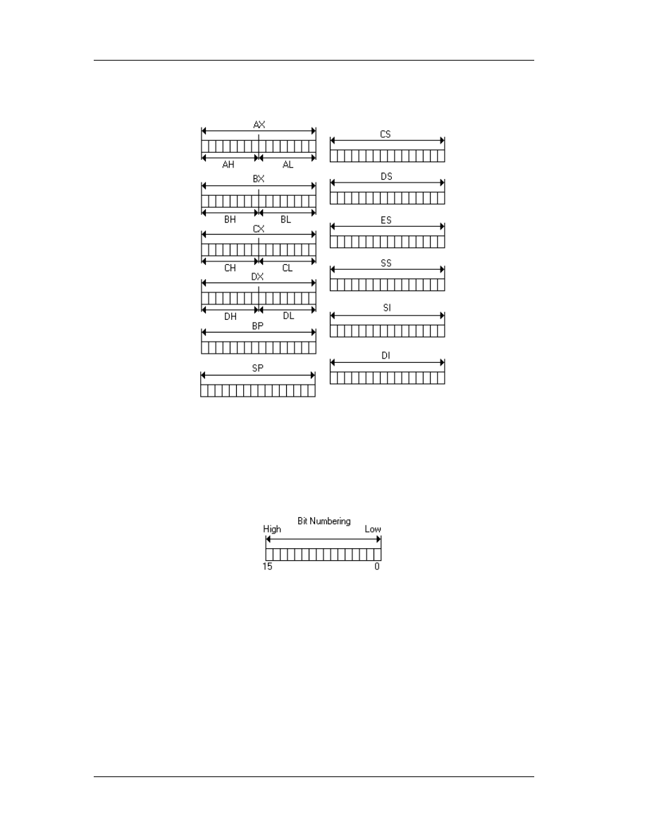
Chapter 4: Basic Concepts of Assembly
69
since they altogether embodied AX, modifying AH is modifying the high 8-bit of AX.
Modifying AL is modifying the low 8-bit of AX.
Bit numbering of a register begins from the lower part. The lowest bit is
numbered as bit 0, the highest bit is numbered as bit 15. So, there are 16 bits.
Therefore, AL occupy bit 0 to bit 7 of AX, AH occupy bit 8 to bit 15 of AX.
Note that x386 processors introduce extended registers. Most of the registers,
except segment registers are enhanced into 32-bit. So, we have extended registers EAX,
EBX, ECX, and so on. AX is only the low 16-bit (bit 0 to 15) of EAX. BX is only the low
16-bit (bit 0 to 15) of EBX and so on. There is no special direct access to the upper 16-
bit (bit 16 to 31) in extended register. Segment registers are not extended. There are no
ECS, or EDS or so.

Chapter 4: Basic Concepts of Assembly
70
4.2 Flag
Flag is actually 16-bit register that contains processor status. Intel doesn't
provide a direct access to it; it is accessed via stack (Via
POPF
and
PUSHF
). However, for
some reason you can then access flag using the assembly instruction
SAHF
and
LAHF
for
just some flag attributes. You can access each flag attribute by using bitwise
AND
operation since each status is mostly represented by just 1 bit. Here's the flag layout:
o
C denotes carry flag (bit 0). It is turned to 1 whenever the last arithmetical
operation, such as adding and subtracting, has “carry” or “borrow,” otherwise 0.
DOS often uses this to indicate errors.
o
P denotes parity flag (bit 2). Rarely used. It will set to 1 if the last operation (any
operation) results even number of bit 1. It is usually used in communication
things.
o
A denotes auxiliary flag (bit 4). Rarely used. It is set in Binary Coded Decimal
(BCD) operations.
o
Z denotes zero flag (bit 6). Usually used to detect whether the last operation
(any operation) holds zero result.
o
S denotes sign flag (bit 7). It is often used to detect whether the last operation
holds negative result. It is set to 1 if the highest bit (bit 7 in bytes, or bit 15 in
words) of the last operation is 1.
o
T denotes trap flag (bit 8). It is only used in debuggers to turn on the step-by-
step feature.
o
I denotes interrupt flag (bit 9). It is used to toggle the interrupt enable or not. If
the bit is set (= 1), then the interrupts are enabled, otherwise disabled. The
default is on.
o
D denotes interrupt flag (bit 10). It is used for directions of string operations. If
the bit is set, then all string operations are done backward. Otherwise, forward.
The default is forward (= 0).

Chapter 4: Basic Concepts of Assembly
71
o
O denotes the overflow flag (bit 11). It is used to detect whether the last
arithmetic operation result has overflowed or not. If the bit is set, then it has
been an overflow.
o
IOPL denotes the I/O Privilege Level flag (bit 12 to 13). It is used to denote the
privilege level of the running programs. It is rarely used in real mode
programming. This flag exists in 286 or better CPUs.
o
N denotes the Nested Task flag (bit 14) this flag is exist on 286 or better CPU.
This is to detect whether it has been multiple task (or exceptions) occur. Rarely
used in practical programming.
o
Upon the most often used flag is O, D, I, S, Z, and C.
386 or better CPUs has enhanced the flag into 32-bit. The logic however remains the
same. We won’t get involved in the 32-bit flag system, since it would be far out of our
scope.
4.3 Memory
Of course the program’s code (code) is placed in the memory. The memory is
actually numbered as the address, starting from 0, 1, 2, until everything has been
mapped. To address data in the memory, CPU uses registers. Originally, CPU only has
16-bit registers, so the maximum amount of memory that can be addressed is 2
16
=
65536 (64K). However, after XT arrives, the memory is extended to 1 MB. That is 16
times bigger than the original.
Unfortunately, the CPU still has 16 bit registers which is, in fact, cannot handle
all the memory. Engineers had to get around with this and the technique called
segmentation was invented. That means the memory is divided virtually into several
areas called segment.
Upon the arrival of segmentation, the segment registers appeared in order to
corporate the idea. The segment registers are 16 bit, too. The idea of the segmentation

Chapter 4: Basic Concepts of Assembly
72
is NOT dividing 1 MB into 16 exact parts. This means that segment registers are only
allowed to have the value of 0 to 15, and this only uses 4 bits.
If the segment number is 0, then we can access the memory 0 to 65536.
Segment number 1 allows us to access memory number 16 to 65552. Segment 2 from
32 to 65568, and so on with the increment of 16. It is obvious that all 1 MB of the
memory is addressable. Why did they do that? It is for the sake of the operating system
memory management stuff. DOS aligns the executed code to the nearest 16 bytes
alignment.
The memory access must be done in a pair of register. The first is the segment
register and next is any register, usually BX, DX, SI or DI. The register pair usually
written like this: ES:DI with a colon between them. The pair is called the
segment:offset pair. So, ES:DI means that the segment part is addressed by ES, and
the offset part is addressed by DI.
If the ES contains 0, and DI is 5, means that we access the memory 5. If ES:DI
= 0001:0005 then it actually access the actual address 21 (1 * 16 + 5 = 21). Remember
the interleaving mentioned above. So, 0000:0021 and 0001:0005 is actually the same
address. How could the processor do that? The register pair segment:offset contains the
logical address. The actual address or the absolute address needs to be calculated
from the logical address. Since the increment of the interleaving is 16, then we need to
multiply the segment value with 16 first, then add it with the offset part.
Usually programmers refer the memory 0 to 640 KB as the low memory. Sometimes it
is called conventional memory. The area above the first 640 KB up to 1 MB is called
upper memory. Then the 64KB after the border of 1 MB is called high memory area
(HMA). Above this point it is either extended or expanded memory.

Chapter 4: Basic Concepts of Assembly
73
Nowadays, the difference between extended memory and expanded memory is
not too clear. It fully depends on the driver.
HIMEM.SYS
provide access to extended
memory.
EMM386.EXE
,
QEMM
,
386MAX
, or so provides the access to expanded memory.
Programmers usually prefer expanded memory to extended, because operations made
in the expanded memory are faster.
4.4 Stacks
When the OS loads the program code into memory, a specific amount of memory
is reserved in order to make the program run as expected. Each program memory mode
behaves differently. However, there is one thing: there must be a room for the code
itself, then there must be room for data, and the last thing is there must be room for
the stack.
The stack is like a temporary area to store things needed in the near future
(while the program is running). It is mainly used to pass the parameter value to
procedures or functions. Sometimes, it also acts as temporary space for allocating local
variables. Hence, the role of the stack is very important.
It works exactly as the stack in linked list! The last item pushed into stack is
going to be popped first. LIFO (Last In First Out) concept works here. At this moment,

Chapter 4: Basic Concepts of Assembly
74
you don't have to know how stack works in depth. The main thing is that you know that
stack here uses the LIFO concept, but it is NOT a linked list.
Adjusting stacks, involves reserving as much memory as needed for stack. If you
use many parameters in your procedure or functions, you need to reserve bigger stack.
Usually 2 KB or 4 KB is enough for many programs. However, if you use a lot of local
variables, you need to reserve more.
4.5 Interrupts
The Interrupt is like its name: it interrupts. Basically, it interrupts processes.
Upon the request of an interrupt, the processor usually stores only the CS:IP and
flag state of the running program, then it goes to the interrupt routine. After processing
the interrupt, the processor restores all states stored and resumes the program
execution. There are three kinds of interrupts: hardware (other than CPU) interrupts,
software interrupts, and CPU-generated interrupts.
Hardware interrupts occur if one of the hardware devices inside the computer
requires immediate processing. Delaying the process could cause unpredictable, or even,
catastrophic effects. Keyboard interrupt is one example. If you press a key in your
keyboard, you generate an interrupt. Keyboard chips notify the processor that they have
a character to send. Can you imagine if the processor ignores the request and go on?
Your key is never processed!
Software interrupts occur if the running program requests the program to be
interrupted and do something else. It is usually like waiting the user input from
keyboard, or may be request the graphic driver to initialize itself to graphic screen.
CPU-generated interrupts occurs if the processor knows that is something
wrong with the running code. It is usually directed for crash protection. If your program
contains instructions that processor doesn't know, the processor interrupts your
program. It also happens if you divide a number with 0 (divide by zero error).

Chapter 4: Basic Concepts of Assembly
75
Interrupts have a lot of uses and in general, they ease the programmers’ lives,
since they handle certain priority events, like changing into graphic screen, waiting for a
key, accessing files, disks and so on are done through interrupts.

Chapter 5: Assembly Commands
76
Chapter 5
5. Assembly Commands
In this chapter, we’ll discuss several technical details of the most important
assembly commands for the reverse engineer. Note, that this information has been
taken from Hackman Disassembler. For a complete and up-to-date assembly instructions
reference, please use Hackman Disassembler. The commands follow in no particular
order.
5.1 CMP: Compare Two Operands
5.1.1 Description
Compares the first source operand with the second source operand and sets the
status flags in the EFLAGS (refers to the extended Flags, for a brief description of how
flags work, please review 4.2) register according to the results. The comparison is
performed by subtracting the second operand from the first operand and then setting
the status flags in the same manner as the SUB instruction. When an immediate value is
used as an operand, it is sign-extended to the length of the first operand.
The CMP instruction is typically used in conjunction with a conditional jump (Jcc),
condition move (CMOVcc), or SETcc instruction. The condition codes used by the Jcc,
CMOVcc, and SETcc instructions are based on the results of a CMP instruction.
5.1.2 Operation
Below, there is a pseudo code fragment to demonstrate how the CPU behaves
upon the execution of a CMP command:
temp -> SRC1 - SignExtend(SRC2);

Chapter 5: Assembly Commands
77
ModifyStatusFlags; (* Modify status flags in the same manner as the SUB instruction*)
The SUB instruction is described later in this chapter.
5.1.3 Opcode Instruction Description
3C ib CMP AL, imm8 Compare imm8 with AL
3D iw CMP AX, imm16 Compare imm16 with AX
3D id CMP EAX, imm32 Compare imm32 with EAX
80 /7 ib CMP r/m8, imm8 Compare imm8 with r/m8
81 /7 iw CMP r/m16, imm16 Compare imm16 with r/m16
81 /7 id CMP r/m32,imm32 Compare imm32 with r/m32
83 /7 ib CMP r/m16,imm8 Compare imm8 with r/m16
83 /7 ib CMP r/m32,imm8 Compare imm8 with r/m32
38 / r CMP r/m8,r8 Compare r8 with r/m8
39 / r CMP r/m16,r16 Compare r16 with r/m16
39 / r CMP r/m32,r32 Compare r32 with r/m32
3A / r CMP r8,r/m8 Compare r/m8 with r8
3B / r CMP r16,r/m16 Compare r/m16 with r16
3B / r CMP r32,r/m32 Compare r/m32 with r32
5.2 J cc: Jump if Condition Is Met
5.2.1 Description
Checks the state of one or more of the status flags in the EFLAGS register (CF,
OF, PF, SF, and ZF) and, if the flags are in the specified state (condition), performs a
jump to the target instruction specified by the destination operand. A condition code
(cc) is associated with each instruction to indicate the condition being tested for. If the
condition is not satisfied, the jump is not performed and execution continues with the
instruction following the Jcc instruction.

Chapter 5: Assembly Commands
78
The target instruction is specified with a relative offset (a signed offset relative to
the current value of the instruction pointer in the EIP register). A relative offset (rel8,
rel16, or rel32) is generally specified as a label in assembly code, but at the machine
code level, it is encoded as a signed, 8-bit or 32-bit immediate value, which is added to
the instruction pointer. Instruction coding is most efficient for offsets of –128 to +127. If
the operand-size attribute is 16, the upper two bytes of the EIP register are cleared to
0s, resulting in a maximum instruction pointer size of 16 bits.
The conditions for each Jcc mnemonic are given in the “Description” column of
the table on the preceding page. The terms “less” and “greater” are used for
comparisons of signed integers and the terms “above” and “below” are used for
unsigned integers.
Because a particular state of the status flags can sometimes be interpreted in
two ways, two mnemonics are defined for some opcodes. For example, the JA (jump if
above) instruction and the JNBE (jump if not below or equal) instruction are alternate
mnemonics for the opcode 77H. The Jcc instruction does not support far jumps (jumps
to other code segments). When the target for the conditional jump is in a different
segment, use the opposite condition from the condition being tested for the Jcc
instruction, and then access the target with an unconditional far jump (JMP instruction)
to the other segment. For example, the following conditional far jump is illegal:
JZ FARLABEL;
To accomplish this far jump, use the following two instructions:
JNZ BEYOND;
JMP FARLABEL;
BEYOND:
The JECXZ and JCXZ instructions differ from the other Jcc instructions because
they do not check the status flags. Instead they check the contents of the ECX and CX

Chapter 5: Assembly Commands
79
registers, respectively, for 0. Either the CX or ECX register is chosen according to the
address-size attribute. These instructions are useful at the beginning of a conditional
loop that terminates with a conditional loop instruction (such as LOOPNE). They prevent
entering the loop when the ECX or CX register is equal to 0, which would cause the loop
to execute 2 32 or 64K times, respectively, instead of zero times. All conditional jumps
are converted to code fetches of one or two cache lines, regardless of jump address or
cacheability.
5.2.2 Operation
Below, there is a pseudo code fragment to demonstrate how the CPU behaves
upon the execution of a J xx command:
IF condition
THEN
EIP ¬ EIP + SignExtend(DEST);
IF OperandSize = 16
THEN
EIP ¬ EIP AND 0000FFFFH;
FI;
FI;
5.2.3 Opcode Instruction Description
77 cb JA rel8 Jump short if above (CF=0 and ZF=0)
73 cb JAE rel8 Jump short if above or equal (CF=0)
72 cb JB rel8 Jump short if below (CF=1)
76 cb JBE rel8 Jump short if below or equal (CF=1 or ZF=1)
72 cb JC rel8 Jump short if carry (CF=1)
E3 cb JCXZ rel8 Jump short if CX register is 0
E3 cb JECXZ rel8 Jump short if ECX register is 0
74 cb JE rel8 Jump short if equal (ZF=1)

Chapter 5: Assembly Commands
80
7F cb JG rel8 Jump short if greater (ZF=0 and SF=OF)
7D cb JGE rel8 Jump short if greater or equal (SF=OF)
7C cb JL rel8 Jump short if less (SF<>OF)
7E cb JLE rel8 Jump short if less or equal (ZF=1 or SF<>OF)
76 cb JNA rel8 Jump short if not above (CF=1 or ZF=1)
72 cb JNAE rel8 Jump short if not above or equal (CF=1)
73 cb JNB rel8 Jump short if not below (CF=0)
77 cb JNBE rel8 Jump short if not below or equal (CF=0 and ZF=0)
73 cb JNC rel8 Jump short if not carry (CF=0)
75 cb JNE rel8 Jump short if not equal (ZF=0)
7E cb JNG rel8 Jump short if not greater (ZF=1 or SF<>OF)
7C cb JNGE rel8 Jump short if not greater or equal (SF<>OF)
7D cb JNL rel8 Jump short if not less (SF=OF)
7F cb JNLE rel8 Jump short if not less or equal (ZF=0 and SF=OF)
71 cb JNO rel8 Jump short if not overflow (OF=0)
7B cb JNP rel8 Jump short if not parity (PF=0)
79 cb JNS rel8 Jump short if not sign (SF=0)
75 cb JNZ rel8 Jump short if not zero (ZF=0)
70 cb JO rel8 Jump short if overflow (OF=1)
7A cb JP rel8 Jump short if parity (PF=1)
7A cb JPE rel8 Jump short if parity even (PF=1)
7B cb JPO rel8 Jump short if parity odd (PF=0)
78 cb JS rel8 Jump short if sign (SF=1)
74 cb JZ rel8 Jump short if zero (ZF = 1)
0F 87 cw/cd JA rel16/32 Jump near if above (CF=0 and ZF=0)
0F 83 cw/cd JAE rel16/32 Jump near if above or equal (CF=0)
0F 82 cw/cd JB rel16/32 Jump near if below (CF=1)
0F 86 cw/cd JBE rel16/32 Jump near if below or equal (CF=1 or ZF=1)
0F 82 cw/cd JC rel16/32 Jump near if carry (CF=1)
0F 84 cw/cd JE rel16/32 Jump near if equal (ZF=1)
0F 84 cw/cd JZ rel16/32 Jump near if 0 (ZF=1)
0F 8F cw/cd JG rel16/32 Jump near if greater (ZF=0 and SF=OF)

Chapter 5: Assembly Commands
81
0F 8D cw/cd JGE rel16/32 Jump near if greater or equal (SF=OF)
0F 8C cw/cd JL rel16/32 Jump near if less (SF<>OF)
0F 8E cw/cd JLE rel16/32 Jump near if less or equal (ZF=1 or SF<>OF)
0F 86 cw/cd JNA rel16/32 Jump near if not above (CF=1 or ZF=1)
0F 82 cw/cd JNAE rel16/32 Jump near if not above or equal (CF=1)
0F 83 cw/cd JNB rel16/32 Jump near if not below (CF=0)
0F 87 cw/cd JNBE rel16/32 Jump near if not below or equal (CF=0 and ZF=0)
0F 83 cw/cd JNC rel16/32 Jump near if not carry (CF=0)
0F 85 cw/cd JNE rel16/32 Jump near if not equal (ZF=0)
0F 8E cw/cd JNG rel16/32 Jump near if not greater (ZF=1 or SF<>OF)
0F 8C cw/cd JNGE rel16/32 Jump near if not greater or equal (SF<>OF)
0F 8D cw/cd JNL rel16/32 Jump near if not less (SF=OF)
0F 8F cw/cd JNLE rel16/32 Jump near if not less or equal (ZF=0 and SF=OF)
0F 81 cw/cd JNO rel16/32 Jump near if not overflow (OF=0)
0F 8B cw/cd JNP rel16/32 Jump near if not parity (PF=0)
0F 89 cw/cd JNS rel16/32 Jump near if not sign (SF=0)
0F 85 cw/cd JNZ rel16/32 Jump near if not zero (ZF=0)
0F 80 cw/cd JO rel16/32 Jump near if overflow (OF=1)
0F 8A cw/cd JP rel16/32 Jump near if parity (PF=1)
0F 8A cw/cd JPE rel16/32 Jump near if parity even (PF=1)
0F 8B cw/cd JPO rel16/32 Jump near if parity odd (PF=0)
0F 88 cw/cd JS rel16/32 Jump near if sign (SF=1)
0F 84 cw/cd JZ rel16/32 Jump near if 0 (ZF=1)
5.3 PUSH: Push Word or Doubleword Onto the Stack
5.3.1 Description
Decrements the stack pointer and then stores the source operand on the top of
the stack. The address-size attribute of the stack segment determines the stack pointer
size (16 bits or 32 bits), and the operand-size attribute of the current code segment
determines the amount the stack pointer is decremented (2 bytes or 4 bytes). For

Chapter 5: Assembly Commands
82
example, if these address- and operand-size attributes are 32, the 32-bit ESP register
(stack pointer) is decremented by 4 and, if they are 16, the 16-bit SP register is
decremented by 2.(The B flag in the stack segment’s segment descriptor determines the
stack’s address-size attribute, and the D flag in the current code segment’s segment
descriptor, along with prefixes, determines the operand-size attribute and also the
address-size attribute of the source operand.) Pushing a 16-bit operand when the stack
address-size attribute is 32 can result in a misaligned the stack pointer (that is, the stack
pointer is not aligned on a doubleword boundary).
The PUSH ESP instruction pushes the value of the ESP register as it existed
before the instruction was executed. Thus, if a PUSH instruction uses a memory operand
in which the ESP register is used as a base register for computing the operand address,
the effective address of the operand is computed before the ESP register is
decremented. In the real-address mode, if the ESP or SP register is 1 when the PUSH
instruction is executed, the processor shuts down due to a lack of stack space. No
exception is generated to indicate this condition.
Intel Architecture Compatibility
For Intel Architecture processors from the Intel 286 on, the PUSH ESP instruction
pushes the value of the ESP register as it existed before the instruction was executed.
(This is also true in the real-address and virtual-8086 modes.) For the Intel 8086
processor, the PUSH SP instruction pushes the new value of the SP register (that is the
value after it has been decremented by 2).
5.3.2 Operation
Below, there is a pseudo code fragment to demonstrate how the CPU behaves
upon the execution of a PUSH command:
IF StackAddrSize = 32
THEN

Chapter 5: Assembly Commands
83
IF OperandSize = 32
THEN
ESP ¬ ESP - 4;
SS:ESP ¬ SRC; (* push doubleword *)
ELSE (* OperandSize = 16*)
ESP ¬ ESP - 2;
SS:ESP ¬ SRC; (* push word *)
FI;
ELSE (* StackAddrSize = 16*)
IF OperandSize = 16
THEN
SP ¬ SP - 2;
SS:SP ¬ SRC; (* push word *)
ELSE (* OperandSize = 32*)
SP ¬ SP - 4;
SS:SP ¬ SRC; (* push doubleword *)
FI;
FI;
5.3.3 Opcode Instruction Description
FF /6 PUSH r/m16 Push r/m16
FF /6 PUSH r/m32 Push r/m32
50+ rw PUSH r16 Push r16
50+ rd PUSH r32 Push r32
6A PUSH imm8 Push imm8
68 PUSH imm16 Push imm16
68 PUSH imm32 Push imm32
0E PUSH CS Push CS
16 PUSH SS Push SS
1E PUSH DS Push DS
06 PUSH ES Push ES

Chapter 5: Assembly Commands
84
0F A0 PUSH FS Push FS
0F A8 PUSH GS Push GS
5.4 POP: Pop a Value from the Stack
5.4.1 Description
Loads the value from the top of the stack to the location specified with the
destination operand and then increments the stack pointer. The destination operand can
be a general-purpose register, memory location, or segment register.
The address-size attribute of the stack segment determines the stack pointer size
(16 bits or 32 bits—the source address size), and the operand-size attribute of the
current code segment determines the amount the stack pointer is incremented (2 bytes
or 4 bytes). For example, if these address- and operand-size attributes are 32, the 32-bit
ESP register (stack pointer) is incremented by 4 and, if they are 16, the 16-bit SP
register is incremented by 2.
The B flag in the stack segment’s segment descriptor determines the stack’s
address-size attribute, and the D flag in the current code segment’s segment descriptor,
along with prefixes, determines the operand-size attribute and also the address-size
attribute of the destination operand.
If the destination operand is one of the segment registers DS, ES, FS, GS, or SS,
the value loaded into the register must be a valid segment selector. In protected mode,
popping a segment selector into a segment register automatically causes the descriptor
information associated with that segment selector to be loaded into the hidden
(shadow) part of the segment register and causes the selector and the descriptor
information to be validated (see the “Operation” section).
A null value (0000-0003) may be popped into the DS, ES, FS, or GS register
without causing a general protection fault. However, any subsequent attempt to

Chapter 5: Assembly Commands
85
reference a segment whose corresponding segment register is loaded with a null value
causes a general protection exception (#GP). In this situation, no memory reference
occurs and the saved value of the segment register is null. The POP instruction cannot
pop a value into the CS register. To load the CS register from the stack, use the RET
instruction.
If the ESP register is used as a base register for addressing a destination
operand in memory, the POP instruction computes the effective address of the operand
after it increments the ESP register.
The POP ESP instruction increments the stack pointer (ESP) before data at the
old top of stack is written into the destination.
A POP SS instruction inhibits all interrupts, including the NMI interrupt, until after
execution of the next instruction. This action allows sequential execution of POP SS and
MOV ESP, EBP instructions without the danger of having an invalid stack during an
interrupt 1. However, use of the LSS instruction is the preferred method of loading the
SS and ESP registers.
5.4.2 Operation
Below, there is a pseudo code fragment to demonstrate how the CPU behaves
upon the execution of a POP command:
IF StackAddrSize = 32
THEN
IF OperandSize = 32
THEN
DEST ¬ SS:ESP; (* copy a doubleword *)
ESP ¬ ESP + 4;
ELSE (* OperandSize = 16*)
DEST ¬ SS:ESP; (* copy a word *)

Chapter 5: Assembly Commands
86
ESP ¬ ESP + 2;
FI;
ELSE (* StackAddrSize = 16* )
IF OperandSize = 16
THEN
DEST ¬ SS:SP; (* copy a word *)
SP ¬ SP + 2;
ELSE (* OperandSize = 32 *)
DEST ¬ SS:SP; (* copy a doubleword *)
SP ¬ SP + 4;
FI;
FI;
Loading a segment register while in protected mode results in special checks and
actions, as described in the following listing. These checks are performed on the
segment selector and the segment descriptor it points to.
IF SS is loaded;
THEN
IF segment selector is null
THEN #GP(0);
FI;
IF segment selector index is outside descriptor table limits
OR segment selector's RPL ¹ CPL
OR segment is not a writable data segment
OR DPL ¹ CPL
THEN #GP(selector);
FI;
IF segment not marked present
THEN #SS(selector);
ELSE
SS ¬ segment selector;

Chapter 5: Assembly Commands
87
SS ¬ segment descriptor;
FI;
FI;
IF DS, ES, FS or GS is loaded with non-null selector;
THEN
IF segment selector index is outside descriptor table limits
OR segment is not a data or readable code segment
OR ((segment is a data or nonconforming code segment)
AND (both RPL and CPL > DPL))
THEN #GP(selector);
IF segment not marked present
THEN #NP(selector);
ELSE
SegmentRegister ¬ segment selector;
SegmentRegister ¬ segment descriptor;
FI;
FI;
IF DS, ES, FS or GS is loaded with a null selector;
THEN
SegmentRegister ¬ segment selector;
SegmentRegister ¬ segment descriptor;
FI;
NOTE: in a sequence of instructions that individually delay interrupts past the following
instruction, only the first instruction in the sequence is guaranteed to delay the
interrupt, but subsequent interrupt-delaying instructions may not delay the interrupt.
Thus, in the following instruction sequence:
STI
POP SS
POP ESP

Chapter 5: Assembly Commands
88
Interrupts may be recognized before the POP ESP executes, because STI also
delays interrupts for one instruction.
5.4.3 Opcode Instruction Description
8F /0 POP m16 Pop top of stack into m16; increment stack pointer
8F /0 POP m32 Pop top of stack into m32; increment stack pointer
58+ rw POP r16 Pop top of stack into r16; increment stack pointer
58+ rd POP r32 Pop top of stack into r32; increment stack pointer
1F POP DS Pop top of stack into DS; increment stack pointer
07 POP ES Pop top of stack into ES; increment stack pointer
17 POP SS Pop top of stack into SS; increment stack pointer
0F A1 POP FS Pop top of stack into FS; increment stack pointer
0F A9 POP GS Pop top of stack into GS; increment stack pointer
5.5 AND: Logical AND
5.5.1 Description
Performs a bitwise AND operation on the destination (first) and source (second)
operands and stores the result in the destination operand location. The source operand
can be an immediate, a register, or a memory location; the destination operand can be
a register or a memory location. (However, two memory operands cannot be used in
one instruction.) Each bit of the result of the AND instruction is a 1 if both corresponding
bits of the operands are 1; otherwise, it becomes a 0.
5.5.2 Operation and Example
Pseudo code:
DEST ¬ DEST AND SRC;
Example:

Chapter 5: Assembly Commands
89
Consider the integers 58 and 167. Below is illustrated the result of the operation
58 AND 167. Note that the same skeptic can be extended in 32, 64 or more bit
numbers.
1. Convert number 58 into binary: 00111010
2. Convert number 167 into binary: 10100111
3. Align numbers vertically. If two bits at the same location have the value 1, the
new number should also have the value 1 for the equivalent bit. Else, 0.
00111010
AND
10100111
IS EQUAL
00100010 which is 34.
5.5.3 Opcode Instruction Description
24 ib AND AL, imm8 AL AND imm8
25 iw AND AX, imm16 AX AND i mm16
25 id AND EAX, imm32 EAX AND imm32
80 /4 ib AND r/m8,imm8 r/m8 AND imm8
81 /4 iw AND r/m16,imm16 r/m16 AND imm16
81 /4 id AND r/m32,imm32 r/m32 AND imm32
83 /4 ib AND r/m16,imm8 r/m16 AND imm8 (sign-extended)
83 /4 ib AND r/m32,imm8 r/m32 AND imm8 (sign-extended)
20 /r AND r/m8,r8 r/m8 AND r8
21 / r AND r/m16,r16 r/m16 AND r16
21 / r AND r/m32,r32 r/m32 AND r32
22 / r AND r8,r/m8 r8 AND r/m8
23 / r AND r16,r/m16 r16 AND r/m16
23 / r AND r32,r/m32 r32 AND r/m32

Chapter 5: Assembly Commands
90
5.6 NOT: One's Complement Negation
5.6.1 Description
Performs a bitwise NOT operation (each 1 is cleared to 0, and each 0 is set to 1)
on the destination operand and stores the result in the destination operand location. The
destination operand can be a register or a memory location.
5.6.2 Operation and Example
Pseudo code:
DEST ¬ NOT DEST;
Example:
Consider the integer 167. Below is illustrated the result of the operation NOT
167. Note that the same skeptic can be extended in 32, 64 or more bit numbers.
1. Convert number 167 into binary: 10100111
2. Reverse all bits (1 should be 0 and vice versa)
NOT
10100111
IS EQUAL
01011000 which is 88. (note, it is equal to 255-167)
5.6.3 Opcode Instruction Description
F6 /2 NOT r/m8 Reverse each bit of r/m8
F7 /2 NOT r/m16 Reverse each bit of r/m16
F7 /2 NOT r/m32 Reverse each bit of r/m32

Chapter 5: Assembly Commands
91
5.7 OR: Logical Inclusive OR
5.7.1 Description
Performs a bitwise inclusive OR operation between the destination (first) and
source (second) operands and stores the result in the destination operand location. The
source operand can be an immediate, a register, or a memory location; the destination
operand can be a register or a memory location. (However, two memory operands
cannot be used in one instruction.) Each bit of the result of the OR instruction is 0 if
both corresponding bits of the operands are 0; otherwise, each bit is 1.
5.7.2 Operation and Example
Pseudo code:
DEST ¬ DEST OR SRC;
Example:
Consider the integers 58 and 167. Below is illustrated the result of the operation
58 OR 167. Note that the same skeptic can be extended in 32, 64 or more bit numbers.
1. Convert number 58 into binary: 00111010
2. Convert number 167 into binary: 10100111
3. Align numbers vertically. If two bits at the same location have the value 0, the
new number should also have the value 0 for the equivalent bit. Else, 1.
00111010
OR
10100111
IS EQUAL
10111111 which is 191.

Chapter 5: Assembly Commands
92
5.7.3 Opcode Instruction Description
0C ib OR AL, imm8 AL OR imm8
0D iw OR AX, imm16 AX OR imm16
0D id OR EAX, imm32 EAX OR imm32
80 /1 ib OR r/m8,imm8 r/m8 OR imm8
81 /1 iw OR r/m16,imm16 r/m16 OR imm16
81 /1 id OR r/m32,imm32 r/m32 OR imm32
83 /1 ib OR r/m16,imm8 r/m16 OR imm8 (sign-extended)
83 /1 ib OR r/m32,imm8 r/m32 OR imm8 (sign-extended)
08 / r OR r/m8,r8 r/m8 OR r8
09 / r OR r/m16,r16 r/m16 OR r16
09 / r OR r/m32,r32 r/m32 OR r32
0A / r OR r8,r/m8 r8 OR r/m8
0B / r OR r16,r/m16 r16 OR r/m16
0B / r OR r32,r/m32 r32 OR r/m32
5.8 XOR: Logical Exclusive OR
5.8.1 Description
Performs a bitwise exclusive OR (XOR) operation on the destination (first) and
source (second) operands and stores the result in the destination operand location. The
source operand can be an immediate, a register, or a memory location; the destination
operand can be a register or a memory location. (However, two memory operands
cannot be used in one instruction.) Each bit of the result is 1 if the corresponding bits of
the operands are different; each bit is 0 if the corresponding bits are the same.
5.8.2 Operation and Example
Pseudo code: DEST ¬ DEST XOR SRC;

Chapter 5: Assembly Commands
93
Example:
Consider the integers 58 and 167. Below is illustrated the result of the operation
58 XOR 167. Note that the same skeptic can be extended in 32, 64 or more bit
numbers.
4. Convert number 58 into binary: 00111010
5. Convert number 167 into binary: 10100111
6. Align numbers vertically. If two bits at the same location are the same, the result
is 0 else 1.
00111010
XOR
10100111
IS EQUAL
10011101 which is 157.
5.8.3 Opcode Instruction Description
34 ib XOR AL, imm8 AL XOR imm8
35 iw XOR AX, imm16 AX XOR imm16
35 id XOR EAX, imm32 EAX XOR imm32
80 /6 ib XOR r/m8,imm8 r/m8 XOR imm8
81 /6 iw XOR r/m16,imm16 r/m16 XOR imm16
81 /6 id XOR r/m32,imm32 r/m32 XOR imm32
83 /6 ib XOR r/m16,imm8 r/m16 XOR imm8 (sign-extended)
83 /6 ib XOR r/m32,imm8 r/m32 XOR imm8 (sign-extended)
30 / r XOR r/m8,r8 r/m8 XOR r8
31 / r XOR r/m16,r16 r/m16 XOR r16
31 / r XOR r/m32,r32 r/m32 XOR r32
32 / r XOR r8,r/m8 r8 XOR r/m8
33 / r XOR r16,r/m16 r8 XOR r/m8
33 / r XOR r32,r/m32 r8 XOR r/m8

Chapter 5: Assembly Commands
94
5.9 Other instructions
5.9.1 CALL: Call Procedure
Saves procedure linking information on the stack and branches to the procedure
(called procedure) specified with the destination (target) operand. The target operand
specifies the address of the first instruction in the called procedure. This operand can be
an immediate value, a general-purpose register, or a memory location.
This instruction can be used to execute four different types of calls:
" Near call—A call to a procedure within the current code segment (the segment
currently pointed to by the CS register), sometimes referred to as an
intrasegment call.
" Far call—A call to a procedure located in a different segment than the current
code segment, sometimes referred to as an intersegment call.
" Inter-privilege-level far call—A far call to a procedure in a segment at a different
privilege level than that of the currently executing program or procedure.
" Task switch—A call to a procedure located in a different task.
The latter two call types (inter-privilege-level call and task switch) can only be
executed in protected mode.
5.9.1.1 Near Call
When executing a near call, the processor pushes the value of the EIP register
(which contains the offset of the instruction following the CALL instruction) onto the
stack (for use later as a return-instruction pointer). The processor then branches to the
address in the current code segment specified with the target operand.

Chapter 5: Assembly Commands
95
The target operand specifies either an absolute offset in the code segment (that
is an offset from the base of the code segment) or a relative offset (a signed
displacement relative to the current value of the instruction pointer in the EIP register,
which points to the instruction following the CALL instruction). The CS register is not
changed on near calls.
For a near call, an absolute offset is specified indirectly in a general-purpose
register or a memory location (r/m16 or r/m32). The operand-size attribute determines
the size of the target operand (16 or 32 bits). Absolute offsets are loaded directly into
the EIP register. If the operand-size attribute is 16, the upper two bytes of the EIP
register are cleared to 0s, resulting in a maximum instruction pointer size of 16 bits.
(When accessing an absolute offset indirectly using the stack pointer [ESP] as a base
register, the base value used is the value of the ESP before the instruction executes.)
A relative offset (rel16 or rel32) is generally specified as a label in assembly
code, but at the machine code level, it is encoded as a signed, 16- or 32-bit immediate
value. This value is added to the value in the EIP register. As with absolute offsets, the
operand-size attribute determines the size of the target operand (16 or 32 bits).
5.9.1.2 Far Calls in Real-Address or Virtual-8086 Mode
When executing a far call in real-address or virtual-8086 mode, the processor
pushes the current value of both the CS and EIP registers onto the stack for use as a
return-instruction pointer. The processor then performs a “far branch” to the code
segment and offset specified with the target operand for the called procedure. Here the
target operand specifies an absolute far address either directly with a pointer (ptr16:16
or ptr16:32) or indirectly with a memory location (m16:16 or m16:32).
With the pointer method, the segment and offset of the called procedure is
encoded in the instruction, using a 4-byte (16-bit operand size) or 6-byte (32-bit
operand size) far address immediate. With the indirect method, the target operand

Chapter 5: Assembly Commands
96
specifies a memory location that contains a 4-byte (16-bit operand size) or 6-byte (32-
bit operand size) far address.
The operand-size attribute determines the size of the offset (16 or 32 bits) in the
far address. The far address is loaded directly into the CS and EIP registers. If the
operand-size attribute is 16, the upper two bytes of the EIP register are cleared to 0s.
5.9.1.3 Far Calls in Protected Mode
When the processor is operating in protected mode, the CALL instruction can be
used to perform the following three types of far calls:
" Far call to the same privilege level.
" Far call to a different privilege level (inter-privilege level call).
" Task switch (far call to another task).
In protected mode, the processor always uses the segment selector part of the
far address to access the corresponding descriptor in the GDT or LDT. The descriptor
type (code segment, call gate, task gate, or TSS) and access rights determine the type
of call operation to be performed. If the selected descriptor is for a code segment, a far
call to a code segment at the same privilege level is performed.
If the selected code segment is at a different privilege level and the code
segment is non-conforming, a general-protection exception is generated. A far call to
the same privilege level in protected mode is very similar to one carried out in real-
address or virtual-8086 mode. The target operand specifies an absolute far address
either directly with a pointer (ptr16:16 or ptr16:32) or indirectly with a memory location
(m16:16 or m16:32).
The operand-size attribute determines the size of the offset (16 or 32 bits) in the
far address. The new code segment selector and its descriptor are loaded into CS
register, and the offset from the instruction is loaded into the EIP register.

Chapter 5: Assembly Commands
97
Note that a call gate (described in the next paragraph) can also be used to
perform far call to a code segment at the same privilege level. Using this mechanism
provides an extra level of indirection and is the preferred method of making calls
between 16-bit and 32-bit code segments. When executing an inter-privilege-level far
call, the code segment for the procedure being called must be accessed through a call
gate.
The segment selector specified by the target operand identifies the call gate.
Here again, the target operand can specify the call gate segment selector either directly
with a pointer (ptr16:16 or ptr16:32) or indirectly with a memory location (m16:16 or
m16:32). The processor obtains the segment selector for the new code segment and the
new instruction pointer (offset) from the call gate descriptor.
The offset from the target operand is ignored when a call gate is used. On inter-
privilege-level calls, the processor switches to the stack for the privilege level of the
called procedure. The segment selector for the new stack segment is specified in the
TSS for the currently running task. The branch to the new code segment occurs after
the stack switch. (Note that when using a call gate to perform a far call to a segment at
the same privilege level, no stack switch occurs.)
On the new stack, the processor pushes the segment selector and stack pointer
for the calling procedure’s stack, an (optional) set of parameters from the calling
procedures stack, and the segment selector and instruction pointer for the calling
procedure’s code segment.
A value in the call gate descriptor determines how many parameters to copy to
the new stack. Finally, the processor branches to the address of the procedure being
called within the new code segment.

Chapter 5: Assembly Commands
98
Executing a task switch with the CALL instruction is somewhat similar to
executing a call through a call gate. Here the target operand specifies the segment
selector of the task gate for the task being switched to (and the offset in the target
operand is ignored.) The task gate in turn points to the TSS for the task, which contains
the segment selectors for the task’s code and stack segments.
The TSS also contains the EIP value for the next instruction that was to be
executed before the task was suspended. This instruction pointer value is loaded into
EIP register so that the task begins executing again at this next instruction. The CALL
instruction can also specify the segment selector of the TSS directly, which eliminates
the indirection of the task gate.
Note that when you execute at task switch with a CALL instruction, the nested
task flag (NT) is set in the EFLAGS register and the new TSS’s previous task link field is
loaded with the old tasks TSS selector. Code is expected to suspend this nested task by
executing an IRET instruction, which, because the NT flag is set, will automatically use
the previous task link to return to the calling task. Switching tasks with the CALL
instruction differs in this regard from the JMP instruction which does not set the NT flag
and therefore does not expect an IRET instruction to suspend the task.
5.9.1.4 Mixing 16-Bit and 32-Bit Calls
When making far calls between 16-bit and 32-bit code segments, the calls should
be made through a call gate. If the far call is from a 32-bit code segment to a 16-bit
code segment, the call should be made from the first 64 KBytes of the 32-bit code
segment. This is because the operand-size attribute of the instruction is set to 16, so
only a 16-bit return address offset is saved.
Also, the call should be made using a 16-bit call gate so that 16-bit values will be
pushed on the stack.

Chapter 5: Assembly Commands
99
5.9.2 ADD: Add
Adds the first operand (destination operand) and the second operand (source
operand) and stores the result in the destination operand. The destination operand can
be a register or a memory location; the source operand can be an immediate, a register,
or a memory location. (However, two memory operands cannot be used in one
instruction.) When an immediate value is used as an operand, it is sign-extended to the
length of the destination operand format.
The ADD instruction does not distinguish between signed or unsigned operands.
Instead, the processor evaluates the result for both data types and sets the OF and CF
flags to indicate a carry in the signed or unsigned result, respectively. The SF flag
indicates the sign of the signed result.
5.9.3 SUB: Subtract
Subtracts the second operand (source operand) from the first operand
(destination operand) and stores the result in the destination operand. The destination
operand can be a register or a memory location; the source operand can be an
immediate, register, or memory location. (However, two memory operands cannot be
used in one instruction.) When an immediate value is used as an operand, it is sign-
extended to the length of the destination operand format.
The SUB instruction does not distinguish between signed or unsigned operands.
Instead, the processor evaluates the result for both data types and sets the OF and CF
flags to indicate a borrow in the signed or unsigned result, respectively. The SF flag
indicates the sign of the signed result.
5.9.4 MUL: Unsigned Multiply
Performs an unsigned multiplication of the first operand (destination operand)
and the second operand (source operand) and stores the result in the destination
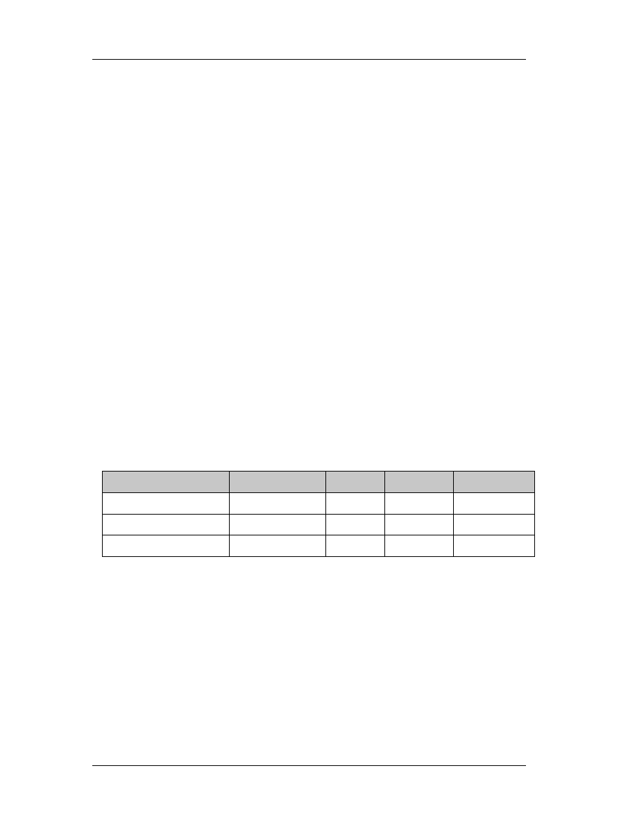
Chapter 5: Assembly Commands
100
operand. The destination operand is an implied operand located in register AL, AX or
EAX (depending on the size of the operand); the source operand is located in a general-
purpose register or a memory location.
The result is stored in register AX, register pair DX:AX, or register pair EDX:EAX
(depending on the operand size), with the high-order bits of the product contained in
register AH, DX, or EDX, respectively. If the high-order bits of the product are 0, the CF
and OF flags are cleared; otherwise, the flags are set.
5.9.5 DIV: Unsigned Divide
Divides (unsigned) the value in the AX register, DX:AX register pair, or EDX:EAX
register pair (dividend) by the source operand (divisor) and stores the result in the AX
(AH:AL), DX:AX, or EDX:EAX registers. The source operand can be a general-purpose
register or a memory location.
The action of this instruction depends on the operand size, as shown in the
following table:
Operand Size
Dividend
Divisor
Quotient
Remainder
Word/byte AX
r/m8
AL
AH
255
Doubleword/word DX:AX
r/m16 AX DX
65535
Quadword/doubleword EDX:EAX r/m32 EAX
EDX
2^32 - 1
Non-integral results are truncated (chopped) towards 0. The remainder is always
less than the divisor in magnitude. Overflow is indicated with the #DE (divide error)
exception rather than with the CF flag.
5.9.6 MOV: Move
Copies the second operand (source operand) to the first operand (destination
operand). The source operand can be an immediate value, general-purpose register,

Chapter 5: Assembly Commands
101
segment register, or memory location; the destination register can be a general-purpose
register, segment register, or memory location. Both operands must be the same size,
which can be a byte, a word, or a doubleword.
The MOV instruction cannot be used to load the CS register. Attempting to do so
results in an invalid opcode exception (#UD). To load the CS register, use the far JMP,
CALL, or RET instruction.
If the destination operand is a segment register (DS, ES, FS, GS, or SS), the
source operand must be a valid segment selector. In protected mode, moving a
segment selector into a segment register automatically causes the segment descriptor
information associated with that segment selector to be loaded into the hidden
(shadow) part of the segment register. While loading this information, the segment
selector and segment descriptor information is validated (see the “Operation”
algorithm). The segment descriptor data is obtained from the GDT or LDT entry for the
specified segment selector.
A null segment selector (values 0000-0003) can be loaded into the DS, ES, FS,
and GS registers without causing a protection exception. However, any subsequent
attempt to reference a segment whose corresponding segment register is loaded with a
null value causes a general protection exception (#GP) and no memory reference
occurs.
Loading the SS register with a MOV instruction inhibits all interrupts until after
the execution of the next instruction. This operation allows a stack pointer to be loaded
into the ESP register with the next instruction (MOV ESP, stack-pointer value) before an
interrupt occurs 1 . The LSS instruction offers a more efficient method of loading the SS
and ESP registers.
When operating in 32-bit mode and moving data between a segment register
and a general-purpose register, the Intel Architecture 32-bit processors do not require
the use of the 16-bit operand-size prefix (a byte with the value 66H) with this

Chapter 5: Assembly Commands
102
instruction, but most assemblers will insert it if the standard form of the instruction is
used (for example, MOV DS, AX). The processor will execute this instruction correctly,
but it will usually require an extra clock. With most assemblers, using the instruction
form MOV DS, EAX will avoid this unneeded 66H prefix.
When the processor executes the instruction with a 32-bit general-purpose
register, it assumes that the 16 least-significant bits of the general-purpose register are
the destination or source operand. If the register is a destination operand, the resulting
value in the two high-order bytes of the register is implementation dependent. For the
Pentium Pro processor, the two high-order bytes are filled with zeros; for earlier 32-bit
Intel Architecture processors, the two high order bytes are undefined.
NOTE: In a sequence of instructions that individually delay interrupts past the following
instruction, only the first instruction in the sequence is guaranteed to delay the
interrupt, but subsequent interrupt-delaying instructions may not delay the interrupt.
Thus, in the following instruction sequence:
STI
MOV SS, EAX
MOV ESP, EBP
Interrupts may be recognized before MOV ESP, EBP executes, because STI also
delays interrupts for one instruction.
Chapter 6: Using the Debugger
103
Chapter 6
6. SoftIce for Windows
Throughout the rest of the lectures notes, we’ll be using SoftIce 4.0x debugger
from Numega (
). The main advantage of SoftIce is the ability
to load before windows. This allows us to debug even Windows themselves. It also
intercepts crashes and gives us helpful debugging information. However, since it is a
kernel mode debugger, it lacks a nice graphic user interface, and peripheral support.
That is, if i.e. you are using a laptop and have plugged in external devices through a
dock station, you won’t be able to use them. Get SoftIce and make sure that it is the
right version for the operating system you have. Windows 9x have a different version
than Windows NT/2000. Windows Me is not supported, although there is an article at
Numega prompting you to download and install the DDK for Windows Me. (for more
information see
http://www.numega.com/support/knowledgebase/docs/1078.stm
6.1 Installing SoftIce
Double click the single installation file. The standard installation process will
initiate (InstallShield). Click Next. Read and agree with the license agreement! If you
don’t agree with the terms listed there, the setup will cease. The next dialog box
requires you to enter the serial number of the product. The serial number is different for
the two SoftIce versions (Win 9x and NT/2000). Click Next.
We’ll leave the default installation directory as-is. If for some reason you want to
alter the installation directory you may do so, but be warned that the absolute paths
given in the rest of these notes have to point to the directory that you’ve used for the
installation. Click Next.

Chapter 6: Using the Debugger
104
Select all four installation options. You may want to skip demonstration files if
you like (or help files and online books). A full installation will occupy approximately 13
MB of hard disk space. Click Next.
Unless you are completely sure about your graphic display and selecting it and
testing it is successful, leave the default VGA adapter. Note that it is wise to press the
Test button even if you leave the default VGA adapter checked. Monochrome
card/monitor should be left unchecked, while the Universal Video Driver should remain
checked. Click Next.
Do not select a mouse device yet; this can be done later. However, if you do
select a mouse driver, please make sure that you make the right selection. Click Next.
Now, the installation process requires permission to modify your autoexec.bat file. You
should grant this permission by leaving the first option checked. SoftIce will insert a
couple of important lines in your autoexec.bat file so that SoftIce can be loaded at
startup.
Click Next twice. The installation will copy all necessary (and selected) files onto
your disk. After this procedure is finished, you’ll be prompted to register SoftIce. Select
the last option (register later) and press Next.
A message might appear prompting you to install Adobe Acrobat reader. If you
don’t have this program, you’ll need it in order to read SoftIce’s manual. However, since
you are reading these lecture notes you have it, therefore you will skip this message by
pressing OK. You have to restart your system.
Note that the startup process will be different now. Windows loader starts
SoftIce (so does ntldr for windows NT/2000). When your windows startup, press
CTRL+D to test your installation. If everything was successful, SoftIce window will pop-
up and your Windows will freeze. Press CTRL+D to dismiss SoftIce and proceed to the
next section to configure it properly.

Chapter 6: Using the Debugger
105
6.2 Configuring SoftIce
Go to your programs and you’ll see a new program group named Numega
SoftIce. Inside it, you’ll find two setup options, one for your display adapter and one for
your mouse. You can change the mouse setup if it doesn’t work, but do not mess with
the display adapter settings if it works. SoftIce will appear in a small window. We’ll see
how to change this later.
You also have 4 help files, a standard html read me file, a help file and two
adobe pdf books. All are very helpful especially if you run into unexpected problems.
Finally there is an application named Numega SoftIce Loader. This does not load
SoftIce, it’s name might be confusing. It edits with a graphic interface the initialization
(.ini) file used to store SoftIce’s settings.
Find a file called winice.dat located in the SoftIce installation directory, which
should be C:\program files\Numega\softice95. Open it with notepad. This file holds the
customization settings that SoftIce reads each time it starts.
6.2.1 Resizing Panels
Open SoftIce (press CTRL+D). Type lines. On the bottom line, you’ll see a help
line, explaining you what this command does. Press space once. You’ll then see what
parameters the lines command accepts. I’ve used 60. Experiment with all the numbers
you see. Then, if you want to make your changes final (remain the same each time
SoftIce is running), go to notepad, where the winice.dat file is, and save this setting:
INIT="X;" is replaced by INIT="lines 60;"
Save your changes in notepad. In order to change the number of columns in the
window, the process is the same, but the command used is width. So, type width and
SoftIce will tell you what width does. Press space and you’ll get the range of settings

Chapter 6: Using the Debugger
106
you can use. I’ve used 80. The setting you have to put in winice.dat file is “width=80;”
like you did with the lines command, so you’ll have:
INIT="lines 60;width=80;"
6.2.2 Panels
SoftIce has a lot of panels, which are all configurable. That is, you can hide or
unhide each one of them and of course resize them, with or without the help of your
mouse. We’ll be using the keyboard commands just in case your mouse is not working.
Command
Explanation
WC [number] If no number is specified, it toggles the code window. If a number is
present, it sets the code window lines equal to that number.
(Recommended: 25, it’s a very important window!)
WR
Toggles the registers window, which is on the top part of the window. It
is recommended that the registers’ window is always on.
WD [number] Number behaves as in WC command. This toggles the data window,
which can be used as a hex editor. You may want to close this window
and free up some space.
WF
Toggles the floating stack pointers window. We won’t use this window.
WL
Toggles the locals window. We won’t use this window.
WS
Toggles the stack window. We won’t use this window much.
WW
Toggles the watch window. Set wathes with the watch <address>
command. This is very useful and we will need it in the future but not in
present.
To make all changes permanent, store the settings in winice.dat file. Here’s what
I am using:
INIT="lines 60;code on;wd 13;wc 25;wr;ww 6; faults off;"

Chapter 6: Using the Debugger
107
6.2.3 Other Useful Settings
The
code command toggles on and off the code column in the disassembly
window. The code window is the second column from left to right and has the opcodes
of the functions that are disassembled. If it is off, then there are only three columns
instead of four.
It is convenient to set faults off by default. This will force SoftIce not to pop-up
every time a windows application crashes. Besides, we don’t want to debug everything!
It is necessary to set faults on when we debug our own applications since in case of a
fault, SoftIce won’t pop up when faults are set to off.
If CTRL+D is not convenient for you, you can always use the altkey command
to change it. The syntax is ALTKEY (CTRL or ALT) key. For example, altkey alt F will
replace CTRL+D shortcut with ALT+F.
You probably have noticed by now that the up and down cursors are used to
navigate through the previous commands in the command panel. Also, note that
entering cls will allow you to clear SoftIce’s panel. Set mouse x, sets the mouse speed
from 0 (slowest) to 3 (fastest).
All these settings (and more) can be saved in winice.dat file, so that they’ll be
restored each time SoftIce is initialized:
INIT="lines 60;code on;wd 13;wc 25;ww 6;wl;dex 1 ss:esp;faults off;"
INIT="altkey ctrl d;watch es:di;watch eax;watch *es:di;set mouse 3;cls;X;"
6.2.4 SoftIce Window
Since everything freezes, it’s not that easy to take a snapshot of SoftIce’s
window. There is a way though, freeze something in the background, pop up SoftIce

Chapter 6: Using the Debugger
108
and close it. SoftIce will remain on the frozen window, since painting is unavailable for
frozen applications. Then, you can probably take a snapshot of your screen (or maybe
not, since SoftIce uses a different display driver)
+------------------------------------------------------------------------------+
| EAX=... This is the registers window, activate it |
| EDI=... by typing wr |
+------------------------------------------------------------------------------+
| es:di=... This is the watch window, activate it by typing ww. To watch |
| something, type watch bla, eg watch eax |
+------------------------------------------------------------------------------+
|
xxxx:yyyyyyyy 01 02 03 04 05 06 07 08-09 10 11 12 13 14 15 16 ...............
|
|
xxxx:yyyyyyyy 01 02 03 04 05 06 07 08-09 10 11 12 13 14 15 16 ...............
|
| |
| This is the data window, activate it by typing wd. It is here that you can |
| see what's stored in memory. |
+------------------------------------------------------------------------------+
|
0028:C000A010 7902 JNS C000A014 (JUMP )
|
|
0028:C000A012 33C0 XOR EAX,EAX
|
|
0028:C000A014 83E81F SUB EAX,1F
|
| |
| This is the code window, where the assembly commands the target is executing |
| are displayed. Activate this window by typing wc. |
+------------------------------------------------------------------------------+
|:< type your commands here > |
| |
| Well this is where you type your commands |
+------------------------------------------------------------------------------+
6.2.5 Symbols
Symbols, are DLL functions that are imported in SoftIce, so the program know
what parameters are taken as arguments and what is returned (if something is
returned). Symbols are located in the winice.dat file, at the end of the file with a
semicolon in front of them, which is like a remark. Removing these semicolons is
required in order to import the symbols and breakpoint them.
;EXP=c:\windows\system\kernel32.dll
;EXP=c:\windows\system\user32.dll
;EXP=c:\windows\system\gdi32.dll

Chapter 6: Using the Debugger
109
;EXP=c:\windows\system\comdlg32.dll
;EXP=c:\windows\system\shell32.dll
;EXP=c:\windows\system\advapi32.dll
;EXP=c:\windows\system\shell232.dll
;EXP=c:\windows\system\comctl32.dll
….
Please note that although it would be nice to breakpoint all modules (windows
modules and program dlls), that’s impossible since they would occupy too much
resources. So, we’ll just breakpoint some of the most “popular” modules like
kernel32.dll, user32.dll, comdlg32.dll and advapi32.dll. You can of course breakpoint all
of the default entries in the SoftIce winice.dat module.
There is also another point you need to take care of, the path of the modules. It
has to be an absolute path. So, if your windows installation directory is C:\WINNT,
probably kernel32.dll resides in C:\Winnt\system32\kernel32.dll. If you are unsure, then
you can use the Search for Files function to search for the modules you need to
breakpoint.
6.3 Breakpoints
In the following table, all common breakpoint related commands are listed. Of
course, there are many more shortcuts and commands related to breakpoints. You are
advised to consult SoftIce manuals for more information on how to work with
breakpoints. Before you try to use breakpoint, make sure that you’ve been through 6.2.5
paragraph and you completely understand what are symbols and in which dynamic link
library the function you wish to breakpoint resides.
Since the names of the functions are not available in Windows, you should
download Platform SDK from Microsoft web site (
contains all the names of the (documented) functions, the DLL in which they reside and

Chapter 6: Using the Debugger
110
information on their usage. You are not required to do so, but it will help you if you are
interested in RE.
Use
the
bpx command to set breakpoint on execution. This command takes as
its only argument the function name. On execution means that SoftIce will pop up when
this command is called. Then, you can easily navigate to the caller function. Note that in
order to set a breakpoint, you must have the symbols imported (see 6.2.5 for
information on how to breakpoint symbols). If you do not know the name of the
function you wish to set a breakpoint on, then consult the Microsoft platform SDK for an
up-to-date list. Some functions are operating system specific.
All the breakpoints are stored in the breakpoint list. To view items in the
breakpoint list, type bl in the command line. The first column indicates the breakpoint
index, which starts counting from 0. Therefore, the second index will be 1, the third 2
and so on. The index is very useful when we want to edit the breakpoint. We edit an
existing breakpoint with the instruction bpe <index>. Consider the following example:
bpx getdlgitemtexta
" Here we set a breakpoint on execution of the function “getdlgitemtexta”. Softice
needs the symbols of the user32.dll module, since this function is a part of the
user32.dll module.
bl
" We get the breakpoint list. Note that SoftIce starts listing breakpoints with their
indices (00), type (BPX = on execution) and module!function name, i.e.
USER32.DLL!GetDlgItemTextA. SoftIce automatically recognizes that this
function belongs to user32.dll. If it can’t find an appropriate module, then you
have to either edit winice.dat (see 6.2.5) or use another function name.
bpe 0
" We decide that this breakpoint is not correct, so we want to edit it. SoftIce will
put us in an edit mode, with the current breakpoint’s value in memory 0.
Chapter 6: Using the Debugger
111
bpx getdlgitemtextw
" This will replace getdlgitemtexta with getdlgitemtextw. To verify changes, all we
have to do is use bl.
To remove all or some of the breakpoints that we’ve set, we have to use bc
command (breakpoint clear). If a star (*) is used as an argument, all breakpoints will be
cleared. Else, we must indicate the number of the breakpoint we wish to remove (use bl
to retrieve the number).
Occasionally, we may find that all breakpoints in memory are not that useful.
Therefore, we might want to disable some or all of them without erasing them. If we
erase them, we should type them back in the next time we would like to use them. If
we disable them, all that is needed is to enable them.
For this purpose, we are going to use bd and be commands that take the same
arguments with bc. If a star (*) is used, all breakpoint will be disabled or enabled
respectively, otherwise the breakpoint that corresponds to the index used will be
disabled or enabled. Note that when we list the breakpoints (bl), disabled breakpoints
are listed with a * after their indices.
Command
Explanation
bpx <name>
This command sets a breakpoint on execution. You can’t set the
same breakpoint twice. An error will appear (duplicate breakpoint).
Bl
Lists all breakpoint
bpe <index>
Edit a breakpoint that you’ve already defined. To see what is the
index of the breakpoint you are interested in, use bl.
bc * or <index>
Clear one or all breakpoints.
bd * or <index> Disables one or all breakpoints.
be * or <index>
Enabes one or all breakpoints.
bh
Breakpoint history, to easily navigate through your past actions.

Chapter 6: Using the Debugger
112
Some times it’s not enough to set breakpoints on execution only. SoftIce is
extremely versatile and convenient in breakpointing other things and work in memory
mode or hardware mode. That’s why it’s very useful when debugging device drivers or
Windows.
" Bmsg breakpoints on windows messages
" Bpint breakpoints on interrupts
" Bpio breakpoints on i/o access
" Bpm breakpoints on memory access (can be bpm, bpmb, bpmd, bpmw)
" Bpr breakpoints on memory range (very, very useful), see also bprw.
Also, one can find useful the bpt (template) and bstat (statistics), but these
commands are far away from the scope of these notes and won’t be described or used.
6.3 Useful Functions
GetDlgTextItemA is invoked each time a string from a text box is retrieved.
Therefore, we can rely on the fact that each time we enter something in a text box and
the program tries to reach the data contained there, this function will be executed.
Hmemcpy is even more powerful than the previous, since this function will
always be invoked. Consider the case where the programmer bypasses getdlgtextitema
by using his own controls and methods. Since the string will be stored in a variable that
resides in memory, hmemcpy will be invoked.
6.4 Navigation in SoftIce
After you’ve set a breakpoint and SoftIce popped up, all you need to find is who
called that function that you’ve breakpointed. That is, the function resides in a module,
whose symbols are imported in SoftIce (see 6.2.5). When SoftIce detects the function, it
means that you are in the module that implements the function and of course you are
not interested in it.
Chapter 6: Using the Debugger
113
The first thing you have to do is move back to the caller. This is done by
pressing F11 (jump to caller). Then you can refer to the following table to start
learning how to navigate through code.
Shortcut Explanation
F3
Switch between various SoftIce panels if you need to.
F4 Shows
program
screen.
F7
Executes to the cursor.
F8
Executes a single step
F10 Steps
over
F11
Jump to caller, goes to the function that invoked the breakpoint. Actually it
is a “Go to” command.
F12
Returns from the procedure call.
For more information, please consult SoftIce manual. These keyboard shortcuts
can be remapped. There are also command equivalents (i.e. F8 is command T).

Chapter 7: Hackman Editor
114
Chapter 7
7. Hackman Editor
Hackman is a hex editor and disassembler (in the future, there’ll also be an
application level debugger under the same suite). Its purpose is to easily let you export
and modify portions of the source code of any executable program. Of course, it may be
used as a mere hex editor. In the following sections, a brief description of some
interesting functions included in both Lite and Professional editions is available.
7.1 String Manipulation
With this function, you can search in both 16 and 32 bit files (windows 3.x and
windows 32 – 9x, NT, 2000, Me) for strings. A string may be any label that appears as a
menu or as a static or dynamic caption within a program. Take for example Windows
Explorer.
Labels are the menu names (like File) but also some dynamic menus. Try to right
click on an .exe file and on a .dll file. You’ll notice that some menus change in the pop
up menu that appears and some always exist (like Properties, Delete and Rename).
Static menus are called those that always appear, Dynamic are called the menus that
may or may not appear. If you try to delete a file, a dialog box appears asking for your
confirmation. The text on that dialog box is also a string resource.
Almost every application has string resources. The first step in searching for
them is to identify if the program is 16 or 32 bit. The difference between them is that
the 32-bit programs use Unicode strings. This is illustrated below:
" Label “Text” is equal to 5465787400 in standard ANSI (16-bit)
" Label “Text” is equal to 54006500780074000000 in Unicode

Chapter 7: Hackman Editor
115
The difference is that between every two letters, a null character (00) appears.
All you have to do is check the Unicode search each time you want to find a string. (The
find command is in Edit -> Find). Hackman will automatically treat any string as ANSI if
this option is not checked and as Unicode if it is checked.
Once you find the string you want to alter, bear this in mind: you can replace it
with any string of an equal or lower length but you can’t easily insert characters. Say for
example that the string “Text” must be replaced with “Test”. If 32-bit, check Unicode
search and find it. Then go on “x” and type “s”. Press the Save button or from the Write
menu select the Write submenu to save changes.
Now, let’s say that you want to trim this label. Instead of “Text” you need the
label “ext”. Go on T and type e, then x and then t. Move to the hex part, on the number
74 and type 00. This will trim your 4-letter word to a 3-letter word:
" “Text” is initially 54006500780074000000
" Target “ext” will be 65007800740000000000
In the case where we deal with 16-bit files, all we have to do it replace the hex
value of the character we need to trim with 00. The whole process can be further
simplified if we just place a null terminator (00) in any character and ignore the
remaining:
" “Text” is initially 54006500780074000000
" 65000000740065000000 will display “e” since after “e” we have a null.
You have to be very careful when you deal with menus and other strings that
support accelerators. An accelerator is used as a keyboard shortcut, combined with
Alt. Take for example windows explorer. While holding Alt down, press H and then A.
The about box will pop up. The letter that corresponds to a menu, button or other active
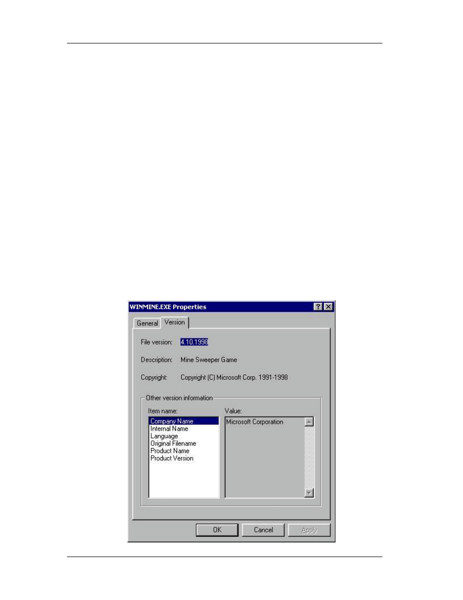
Chapter 7: Hackman Editor
116
element appears with an underscore. Notice the little underline below the letter H in
windows explorer menu.
There is a trick to place an accelerator in resources, even if an accelerator does
not exist. Or you can erase one if it does already exist! The accelerator appears with an
ampersand (&) character just before the letter. For example Help will appear as &Help
and Format with “o” underlined will be F&ormat. Replacing F&ormat with &Format will
replace the accelerator “o” with “f”.
7.2 Version Stamp
Version stamps usually exist in executable files and dynamic link libraries. To
view the version stamp of a file (OS specific), all you have to do is right click it, then
select Properties and click on the version tab. If the version tab does not exist, then
there is no version stamp.
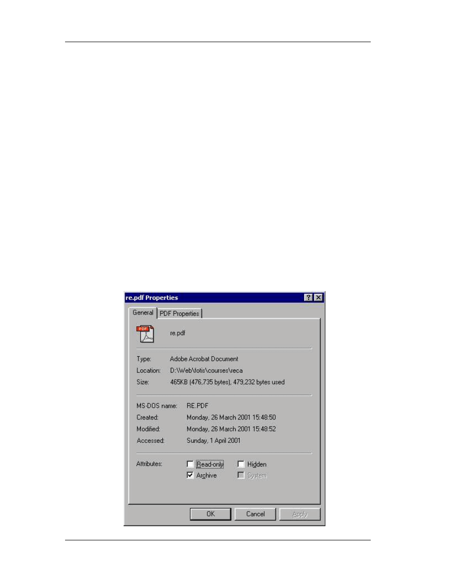
Chapter 7: Hackman Editor
117
To change the version stamp is easy; go to Write menu, the Special and then go
to Version Changer. If the file you’ve opened has a version stamp, the plugin (Version
Changer) will automatically let you edit (with the lower or equal law) the version strings.
This could also be done manually, search for the strings and replace them, but this way
is much faster.
7.3 Date Stamp
Date stamps usually exist for every file. Although creation date and time and last
modification date and time are logically manipulated, the last access time is not. And
this happens because when you right click a file and select properties, you actually
access it and therefore, the stamp changes again. You can change the date stamp of
any file with Hackman. Just open the file in Hackman (it is called logged file), go to
Write, then Special and then select Modify dates.
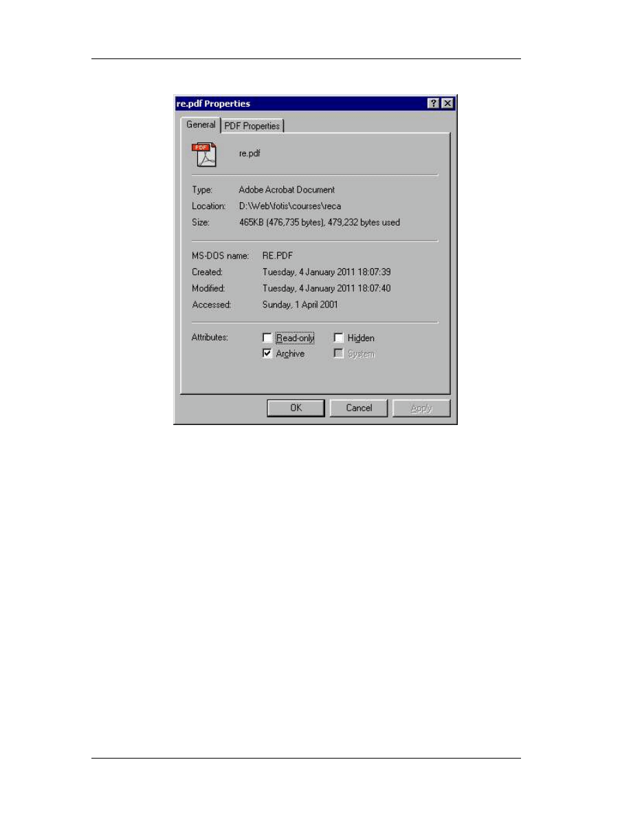
Chapter 7: Hackman Editor
118
7.4 Icon Resources
To extract icon resources from a file, use the Icon Xtractor (From the Write
menu select Icon Xtract). To replace an icon in a file, extract first the icon you want to
replace. Then, open it in Hackman (the extracted file) and select a part of it (double
click for selection, let’s say 15-16 bytes). Press Copy. Go to the target file and press
Find. The paste the bytes onto the find text box.
You’ll find the source code of the icon in the target file. It should be 766 bytes
long, if unsure, check the length of the extracted file. Overwrite this information (delete
it and then use insert file to insert a new icon in the target file).

Chapter 7: Hackman Editor
119
7.5 Other Tools
Other useful tools included in Hackman package:
" Automatic patch: make any changes you want, then use the Make Patch
command under execute menu to create a patch program.
" Disassembler: no description needed!
" Decrypt/Encrypt: strong (up to 128 bit) cryptography routines
" Export: export and filter part or the whole source code in Java, C++, Text,
HTML, Quickbasic and other popular formats. Commands are available for both
the clipboard (Copy As) and a file buffer (File|Export selection as).
" Online libraries: press F1 or from Help menu select books online.
Document Outline
- Table of Contents
- 1. Introduction
- 2. Programming Processors
- 3. Windows Anatomy
- 4. Basic Concepts of Assembly
- 5. Assembly Commands
- 6. SoftIce for Windows
- 7. Hackman Editor
Wyszukiwarka
Podobne podstrony:
NET Reverse Engineering Tutorial Episode 1 by MaDMAn H3rCuL3s
NET Reverse Engineering Tutorial Episode 2 by MaDMAn H3rCuL3s
1 Java Reverse Engineering Tutorial
Running head REVERSE ENGINEERING MALWARE
DTrace The Reverse Engineer’s Unexpected Swiss Army Knife
Reverse Engineering & Memory patching
Reverse Engineering Malware
EDP Gnat Schematics ( Reverse Engineered )
3 01x2b Reversing the engine test 1
3 01x2c Reversing the engine test 2
Diesel engine, Akademia Morska -materiały mechaniczne, szkoła, Mega Szkoła, Szkoła moje
04 Engine
Mazda 6 (Mazda6) Engine Workshop Manual Mzr Cd (Rf Turbo)(3)
M31f1 Engine Controls 1 54
Engine Compartment 4 7
10 Engine Control System
Computer engine control
ARTICLE MAINT INSPECTION ENGINE
price reversals
więcej podobnych podstron