System Remote Controller
PAC-SF44SRA
Schedule Timer
PAC-YT34STA
ON/OFF Remote Controller
PAC-YT40ANRA
This manual describes only the installation of the System Controller, capable of managing and controlling air conditioners, and LOSSNAY. Refer to
the installation manuals enclosed with the air conditioner for details on wiring and installing the air conditioner unit.
To ensure safety, always read
below before starting installation.
1 Safety Precautions
1 Safety Precautions
• The following two symbols are used to denote dangers that may be caused by incorrect use and their degree:
WARNING
CAUTION
This symbol denotes what could lead to serious injury or death if you misuse above remote controllers.
This symbol denotes what could lead to a personal injury or damage to your property if you misuse above remote controllers.
• After reading this installation manual, keep it in a place where the final user can see it anytime he or she wants to it.
When someone moves, repairs or uses above remote controllers, make sure that this manual is forwarded to the final user.
Ask your dealer or technical representative to install the unit.
Never modify or repair above remote controllers.
Do not move and re-install above remote controllers yourself.
Do not install in any place exposed to flammable gas leakage.
Wire so that it does not receive any tension.
Do not touch any control button with your wet hands.
WARNING
CAUTION
Do not wash with water.
When installing the remote controller in a hospital or communication facility, take ample countermeasures against noise.
Do not touch any PCB (Printed Circuit Board) with your hands or
with tools. Do not allow dust to collect on the PCB.
Do not install in any steamy place such a bathroom or kitchen.
Do not remove the insulation sheet on the PCB.
Do not press any control button using a sharp object.
Never apply 100VAC or 200VAC. The maximum voltage that can
be applied on this unit is 30VDC.
Completely seal the wire lead-in port with putty.
Install in a place which is strong enough to withstand the weight
of above remote controllers.
!
Firmly connect the wiring using the specified cables. Carefully
check that the cables do not exert any force on the terminals.
"
Ensure that installation work is done correctly following this
installation manual.
All electrical work must be performed by a licensed technician,
according to local regulations and the instructions given in this
manual.
#
Do not use in any special environment.
Do not install in any place where acidic or alkaline solution or
special spray are often used.
Use standard wires in compliance with the current capacity.
$% % %
& %
Do not install in any place at a temperature of more than 40
;
or
less than 0
;
or exposed to direct sunlight.
Confirm that the box includes the following parts, in addition to this installation manual:
(1) Remote controller (Body, lower case) ........................................................
(2) Cable for external input (5 wire) .................................................................
(3) Cable for external output (4 wire)...............................................................
(4) Cross recessed pan head screw (M4
×
30) ...............................................
(5) Wood screw (4.1
×
16, used for directly hooking to the wall).....................
(6) Room name label or room name record sheet...........................................
(7) Operation Manual.......................................................................................
2 Confirming the Supplied Parts
NOTE:
The remote control cord is not supplied with the product.
Prepare electrical wiring that conforms to the specifications given below.
Electrical wiring specification (CVVS)
Use 1.25mm
2
cable for any extension that exceeds 10m.
¥ 10m or shorter
: 0.75mm
2
two-wire cable
¥ Longer than 10m : 1.25mm
2
two-wire cable
Remote controller wiring entry points can support electrical
wiring of maximum 1.25mm
2
.
However 0.75mm
2
electrical wiring is recommended for use.
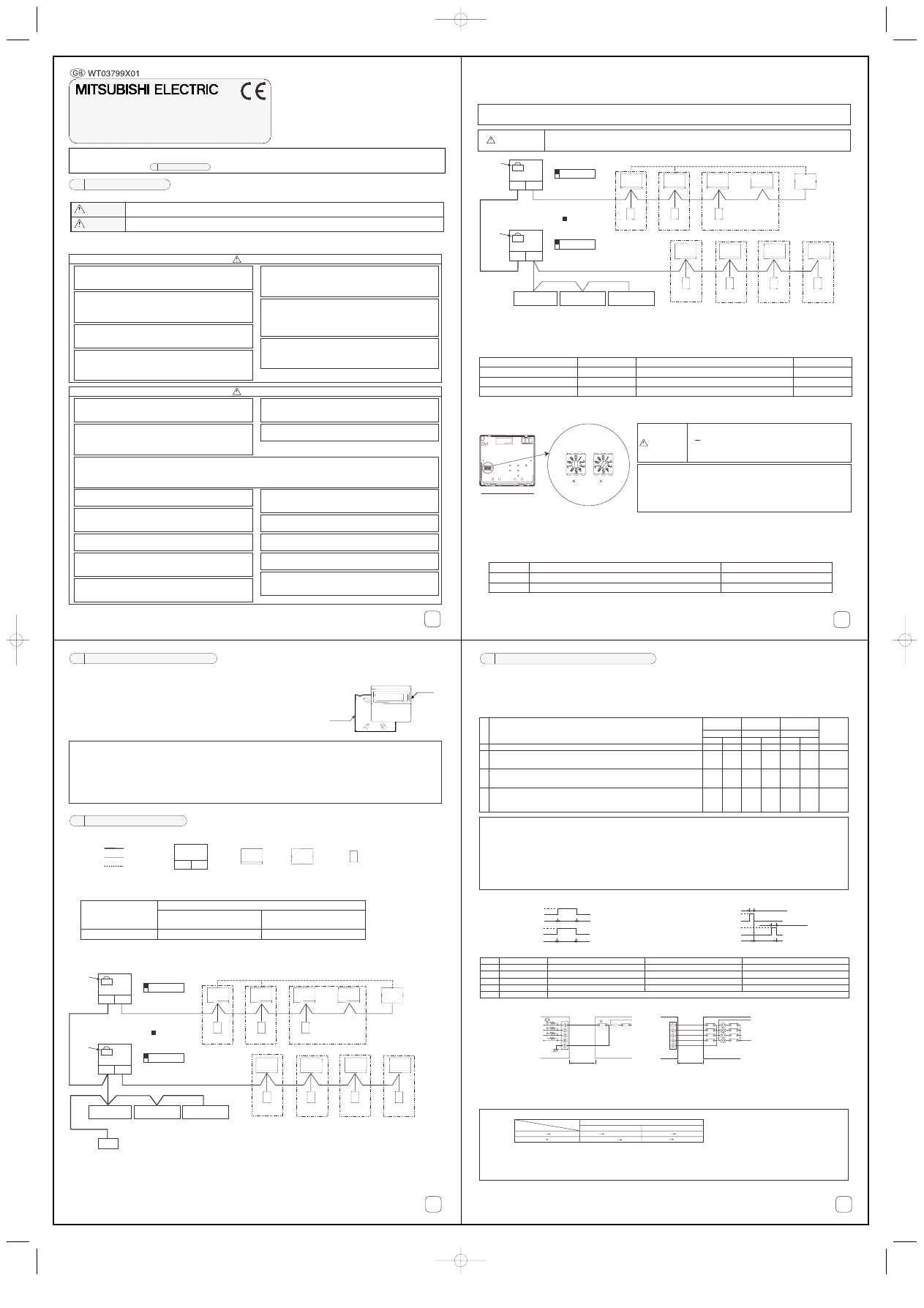
3 System Configurations
(Refer to the "System Design and Work Manual" for the outdoor unit for details.)
!"
(1) When connecting to a central management transmission line
A power supply unit (PAC-SC34KUA) is required.
* The power consumption of the system controller, schedule timer and group remote controller is half of the ON/OFF remote
controller. Thus, interpret the power consumption per unit as half of the ON/OFF remote controller.
!
"
#
Schedule timer
PAC-YT34STA
ON/OFF
remote controller
PAC-YT40ANRA
[051]
CN41
Leave as is
TB7
TB3
1
SW2-1[ON]
ON
OFF
2 3 4 5 6 7 8 9 10
Group 2
[003]
[002]
[001]
[005]
[004]
[006]
[007]
[009]
[101]
[102]
[103]
[105]
[106]
[107]
[201]
[202]
[203]
Group 1
Group 3
Group 4
Group 7
Group 6
Group 5
System
remote controller
PAC-SF44SRA
[008]
[108]
Power supply unit
Model: PAC-SC34KUA
[052]
CN41
TB7
TB3
1
SW2-1[ON]
* Outdoor unit
: SW position
ON
OFF
2 3 4 5 6 7 8 9 10
Leave as is
* Number of units that can be supplied with power supply unit (For above system)
One system remote controller
One schedule timer
One ON/OFF remote controller
1
×1/2 + 1×1/2 + 1×1 = 2 (unit)
!
(2) When connecting to indoor and outdoor transmission line
Up to three system controllers can be connected to the M-NET transmission line's indoor and outdoor transmission line.
A power supply unit is not required in this case, but the short-circuit connector of one of the connected outdoor units must be
connected to CN40.
(3) Setting the various M-NET addresses
The need for address settings and the address setting range will differ according to the system configuration. (The address can-
not be set in duplicate).
(4) Setting the system controller address
(5) When using with master system controller
When connecting multiple system controllers, the system controller with many functions is designated as the "master", and the
system controllers with few functions are designated as the "slaves". The "master/slave" functions of the system controller used
together are as follows.
The functions have a priority in order of G50A (MJ-103MTRA) > PAC-SF44SRA > PAC-YT34STA > PAC-YT40ANRA > PAC-SC30GRA > LMAP02-E.
NOTE :
CAUTION
When the system remote controller is connected to the indoor and outdoor transmission line, the number of indoor units
that can be connected in that refrigerant system will be reduced by two.
When connecting the system controller to the indoor and outdoor transmission line, operations from the
system controller will be disabled if the outdoor unit's power is turned OFF, etc.
Schedule Timer
PAC-YT34STA
ON/OFF
remote controller
PAC-YT40ANRA
Group 2
[003]
[002]
[001]
[005]
[004]
[006]
[007]
[009]
[101]
[102]
[103]
[105]
[106]
[107]
[201]
[202]
[203]
Group 1
Group 3
Group 4
Group 7
Group 6
Group 5
System
Remote Controller
PAC-SF44SRA
[008]
[108]
[051]
CN40
Interchange
short-circuit
connector from
CN41 to CN40.
TB7
TB3
1
SW2-1[ON]
ON
OFF
2 3 4 5 6 7 8 9 10
* Outdoor unit
: SW position
[052]
CN41
Leave as is
TB7
TB3
1
SW2-1[ON]
ON
OFF
2 3 4 5 6 7 8 9 10
System controller
Address setting range
201 to 250
201 to 250
201 to 250
Setting method
Random within address range shown on left
Random within address range shown on left
Set to the minimum group No. to be controlled + "200"
System remote controller
Schedule timer
ON/OFF remote controller
Default address setting
201
202
201
NOTE :
CAUTION
When setting the address, prepare a precision screwdriver
[( ), 2.0mm (w)], and keep the applied load to less than
19.6N.
Setting with other methods could damage the rotary switch.
¥ The address No. that can be set on the remote controller is
within the range of 201-250.
The 100 digit is fixed at "2".
¥ If an address other than those listed above is set, an address
setting error occurs and "AdE" is displayed.
Master side
Slave side
System remote controller (44SRA)/Schedule timer (34STA)
SW3-1: OFF
SW3-1: ON
ON/OFF remote controller (40ANRA)
SW4-1: OFF
SW4-1: ON
* The switch is set to "Master" as the factory setting.
"
When using the external input and output functions, use the external input and output cables provided with the remote controller.
(5 wire cable for input and 4 wire cable for output are provided.)
1. External signal input function
(1) External Input
Emergency stop/Normal, ON/OFF and Prohibit/Permit local remote controller operation control can be applied to all units
being controlled by inputting the no-voltage contact signal from an external source.
(2) Level signal and pulse signal
(3) External input specification
(4) Example of a recommended circuit
•
The relays and extension cables, etc. must be prepared separately at the site.
•
Use a no-voltage contact and minute load relay (minimum application load 5VDC-1mA).
•
The length of the connection cable extension should not exceed 10m. (Use a cable of 0.3mm
2
or thicker.)
•
Cut of the cable not being used close the connector and properly insulate the cut off ends with tape or the like.
4 Using the External Input and Output
No.
1
2
3
4
Do not use external input
Change between Emergency stop/Normal.
Set ON/OFF
Set ON/OFF and Prohibit/Permit.
Input state
—
ON/OFF remote
controller
SW4
2
Schedule timer
SW3
2
3
3
OFF
OFF
OFF
OFF
Level input
Level input
Pulse input
(0.5sec or more)
OFF
ON
ON
ON
OFF
ON
System remote
controller
SW3
2
3
OFF
OFF
OFF
ON
ON
ON
OFF
ON
OFF
ON
ON
ON
OFF
ON
External input signal functions
All units will stop with the external input,and all operations of this unit,other system controllers and
local remote controller will be prohibited.
All units will turn ON/OFF according to the input state. ON/OFF operations using this unit and the
local remote controller will be prohibited when using this function.
All units are started or stopped, or all local remote controller operations are prohibited according to
the input state. When prohibit is input, the local remote controller’s ON/OFF, operation mode, set
temperature and filter reset operations will be prohibited. Operation with this system will be enabled.
NOTE :
For System remote controller and Schedule timer
* If the SW3-4 "operation prohibit setting changeover" is set to "OFF (disable)", use is possible only for emergency stop.
* If the SW3-5 "operation prohibit range setting changeover" is set to "ON (including system controller), operations of the local remote
controller and other system controllers will be prohibited by the prohibit input. If set to "OFF (only local remote controller)", operation
of only the local remote controller will be prohibited. (When the level "emergency stop" or "ON/OFF" is input, operation of the other
system controllers will also be prohibited regardless of the switch setting.)
For ON/OFF remote controller
* All units are stopped when emergency stop is input, and ON/OFF operations of this unit, other system controllers and local remote
controller will be prohibited.
* Only ON/OFF of the local remote controller will be prohibited with the prohibit input.
Contact ON
Contact OFF
Contact ON
Contact OFF
Contact ON
Contact OFF
Contact ON
Contact OFF
OFF
OFF
ON
Normal
Normal
Emergency
STOP
OFF
OFF
ON
(A) Level signal
(B) Pulse signal
0.5sec or more
0.5sec or more
(Example) Case of ON/OFF signal
Signal 1 (ON)
Signal 2 (OFF)
* The same applies to Prohibit/Permit.
!!
"# $
#
%
&'
&'
('
(
!!
)
! "#$
! "#$ #%"
" %
" %
" %
&'
$((
$(( #%"
" %
" %
" %
)% $((* )+,"$)"
#%"
#%"
)+," " " #" #%"
)" " " #" #%"
1
1
1
2
2
1
1
For level signal
Contact operation
OFF ON
Operation state
Emergency stop/Normal
Normal Emergency stop
Emergency stop Normal
ON OFF
External input
For pulse signal
* Operation will continue even if a ON signal is input during operation. (This also applies to OFF, prohibit and enable).
* If the local remote controller is prohibited, ON/OFF, operation mode, temperature and filter reset operations using the local
remote controller will be prohibited. (Only ON/OFF are prohibited for the ON/OFF remote controller.)
* Set the pulse duration (contact ON time) to 0.5sec or more.
ON/OFF
OFF ON
ON OFF
NOTE :
ENG_WT03799X01_A2(QX3_1e) 2/4/03 9:33 AM Page 1
#
(1) Setting local remote controller operation prohibit function from this controller
(excluding ON/OFF remote controller)
When connecting several system controllers, and setting the "local remote controller operation prohibit"
function from this controller, set this controller's SW3-4 "operation prohibit setting changeover" to "ON (permit)".
(2) Changing set temperature display to "Fahrenheit display"
(excluding ON/OFF remote controller)
To prohibit the operation of a system controller other than this system when local remote controller operation prohibit is set from
this system, set SW3-5 "operation prohibit range setting changeover" to "ON (including system controller)".
5 Setting the functions
[System remote controller (SF44SRA)
/Schedule timer (YT34STA)]
[ON/OFF remote controller (YT40ANRA)]
NOTE :
There are other function setting items depending on the device.
For details on setting the functions and the operation methods, refer to (3) List of switch settings and each respective
instruction manual before turning the power ON.
(3) List of switch settings
System remote controller (SF44SRA)
Name
Switch NO.
Setting method
Function
SW3-1
OFF
ON
Master SC setting
Slave SC setting
To set system controller as master
To set system controller as slave
External input function changeover
SW3-2, 3
Operation prohibit range setting changeover
SW3-5
Set the range to control the operation prohibit functions used with this system.
ON
OFF
Including system controller
Only local remote controller To prohibit operation of only the local remote controller
To prohibit operation of the local remote controller
and other system controllers
Not used
SW3-7
Not used
SW3-8
OFF
OFF
OFF
OFF
OFF
OFF
System controller master/slave
setting changeover
Default
setting
1
2
3
4
2
SW3
External input signal function
Do not use external inputs
Change between emergency stop/normal
Input state
Level input
Set ON/OFF
Level input
Set ON/OFF, prohibit/enable
Pulse input (0.5sec or more)
OFF
OFF
ON
ON
3
OFF
ON
OFF
ON
No.
Operation prohibit setting changeover
* Valid only when SW3-4 is ON
SW3-4
Set the local remote controller operation prohibit functions
ON
OFF
Operation prohibit enable
Operation prohibit use disable To not use this system's operation prohibit function
To use this system's operation prohibit function
Schedule timer (YT34STA)
Name
Switch NO.
Setting method
Function
SW3-1
OFF
ON
Master SC setting
Slave SC setting
To set system controller as master
To set system controller as slave
OFF
ON
Celsius display
Fahrenheit display
To display set temperature as Celsius (;)
To display set temperature as Fahrenheit (,)
External input function changeover
SW3-2, 3
Operation prohibit range setting changeover
SW3-5
Set the range to control the operation prohibit functions used with this system.
ON
OFF
Including system controller
Only local remote controller To prohibit operation of only the local remote controller
To prohibit operation of the local remote controller
and other system controllers
Set temperature display changeover
SW3-6
OFF
OFF
OFF
OFF
OFF
System controller master/slave
setting changeover
Default
setting
1
2
3
4
2
SW3
External input signal function
Do not use external inputs
Change between Emergency stop/Normal
Input state
Level input
Set ON/OFF
Level input
Set ON/OFF, prohibit/permit
Pulse input (0.5sec or more)
OFF
OFF
ON
ON
3
OFF
ON
OFF
ON
No.
Operation prohibit setting changeover
* Valid only when SW3-4 is ON
SW3-4
Set the local remote controller operation prohibit functions
ON
OFF
Operation prohibit enable
Operation prohibit use disable To not use this system's operation prohibit function
To use this system's operation prohibit function
OFF
Not used
SW3-7
OFF
Not used
SW3-8
ON/OFF remote controller (YT40ANRA)
Name
Switch NO.
Setting method
Function
SW4-1
OFF
ON
Master SC setting
Slave SC setting
To set system controller as master
To set system controller as slave
External input function changeover
SW4-2, 3
OFF
OFF
System controller master/slave
setting changeover
Default
setting
1
2
3
4
2
SW4
External input signal function
Do not use external inputs
Change between Emergency stop/Normal
Input state
Level input
Set ON/OFF
Level input
Set ON/OFF, prohibit/permit
Pulse input (0.5sec or more)
OFF
OFF
ON
ON
3
OFF
ON
OFF
ON
No.
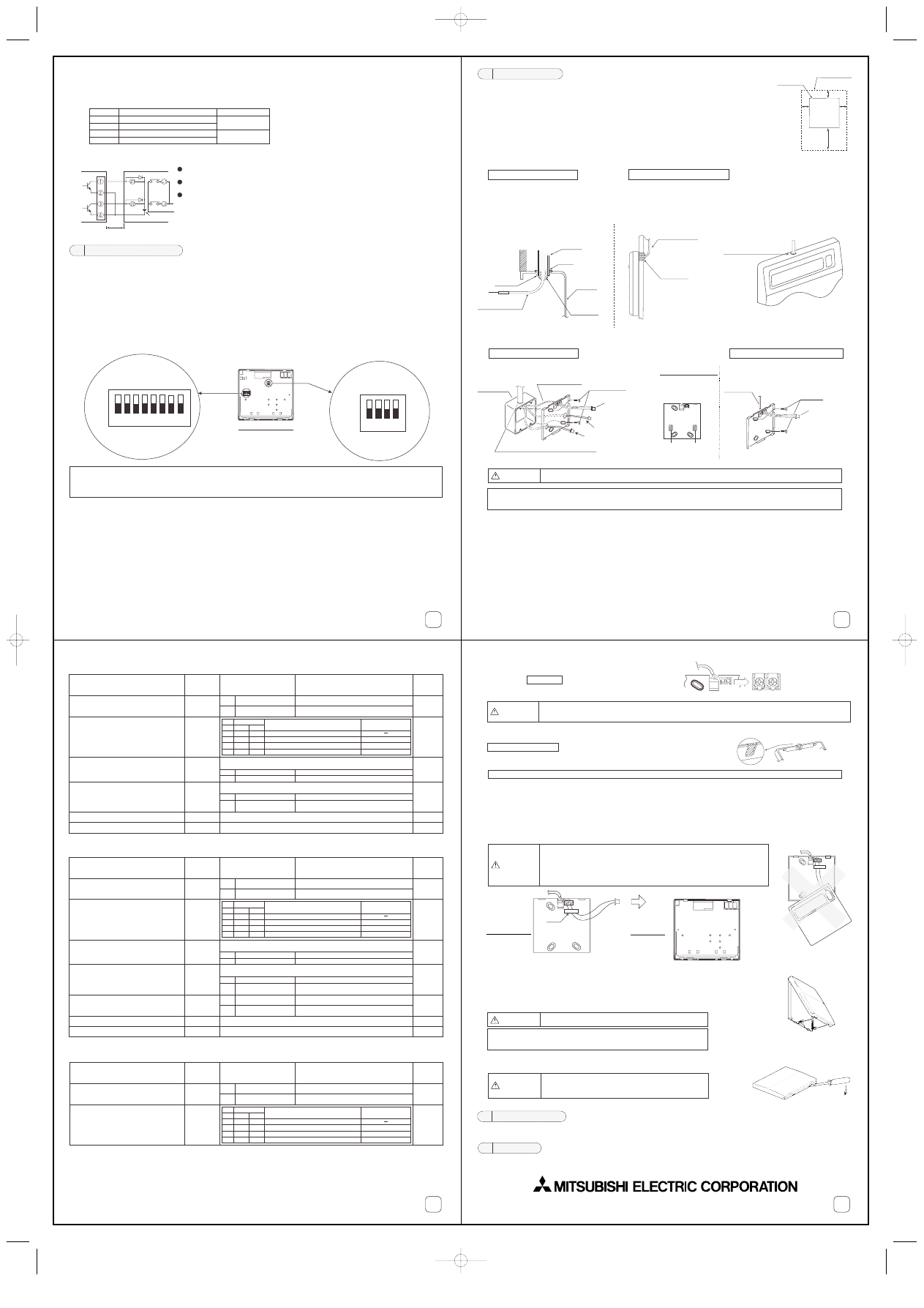
%
(1) Choose a location in which to install the system remote controller (electric
box) in accordance with the following requirements:
q
The space as shown in the diagram at right is required whether the controller is installed
on the wall or in the electric box.
w
Procure the following parts locally.
• Electric box for two units
• Thin-copper wiring pipe
• Locknut and bushing
(2) Seal the remote controller cord lead-in with putty in order to prevent the possible entry of dew, water
droplets, other insects.
• When fitting to the electric box, seal the join
between the electric box and the wiring con-
duit with putty.
(3) Install the lower case on the electric box or directly on the wall.
6 How To Install
• When cutting a hole in the wall for the remote controller cord (when the
remote controller cord exits from the rear of the remote controller), seal this
hole in the same way.
• When fitting directly to the wall as in 3, seal the cut-out in the upper case
with putty.
When using the electric box
When fitting directly on the wall
When using the electric box
When installing directly on the wall
! " #
$
%
& ''!
$( "
#
"
"
)
NOTE :
CAUTION
&
(4) Connect the remote controller cord to the terminal block on the lower case.
Install wiring correctly in accordance with the diagram below.
No polarity
Remote controller cord procured locally.
(5) Wiring hole for fitting directly on the wall (For exposed wiring)
Remote Controller cord
• Cut off the shaded area from the upper cover using a knife, nippers, etc.
• Take out the remote control cord connected to the terminal block via this portion.
External input/output cables (Only in the case when using external input and output functions directly connected to the wall)
• Using a suitable knife or cutting implement, cut and remove the thin walled part on the left and right side of the remote con-
troller main unit.
CN2 side: For external input cable
CN3 side: For external output cable
• Insert the external input/output cables through these points.
(6) Connect the lower case connector to connector CN1 on the upper case.
When using the extemal input and output function, also connect the extemal input cable connector (5 wire) to CN2 and connect
the extemal output cable connector (4 wire) to CN3.
(7) Mount the remote controller main unit.
The first, hook the two upper claws and then fit it as shown in the diagram at right.
When the external input and output functions are used and the lower case cable entry points are
being used, mount the remote controller main unit while pushing the external input/output cables
to the electric box side.
(Push towards the electric box sides from the lower case until the cable sheath part is reached.)
To remove the remote controller body, insert a minus screwdriver into one of the open slots
and move it in the direction of the arrow as shown in the diagram at right.
Initial settings is necessary before test run. Consult the Instruction Book for details of initial settings.
Please perform a test run of each air conditioning unit with the local remote controller.
CAUTION
Do not use crimp terminals to connect to remote controller terminal blocks. It connects to the circuit board and
will cause trouble.
CAUTION
¥ After connecting, do not suspend the case as shown on the right. Doing so
could result in cord breakage or malfunctions, etc.
¥ Always pass the cord through the hook (cord fixing). If not passed through,
force will be directly applied on the terminal block and could break the cord.
¥ Do not remove the PCB protection sheet or PCB. Doing so could lead to faults.
7 Initial Settings
8 Test Run
NOTE:
Remove it before starting.
Press the cover until it snaps shut. If not, it may fall off.
CAUTION
A protective sheet has been affixed to the control panel.
$
In the case of a relay being operated
Maximum
10m
Remote controller
main unit
CN3
yellow
orange
red
Diode (*2)
Power supply (*1)
L1: ON/OFF display lamp
L2: Error display lamp
Z 1
Z 2
brown
Operation coil
Rated voltage: 12VDC, 24VDC
Power consumption: 0.9 W or less
When units are "ON" and an error is occurring,
each element is ON.
The extension length of the connection cable
can be up to 10 m.
The relay, lamps, diodes and extension cables
are not supplied with the product.
For relay Z1, Z2 use the specifications given below.
(*1) Provide a power supply suitable to the relay used. (12VDC
or 24VDC)
(*2) Always insert diodes at both terminals of the relay coil.
! " #
$%%
&$#
' (( ) * (&(
2. External signal output function
(1) External output
In the case when one or more air conditioner units are "ON", and an error is occurring on one or more air conditioner units,
a signal indicating that an error is occurring is output.
(2) External output specification
(3) Example of a recommended circuit
CAUTION
Do not turn the screwdriver in the slot.
Doing so may damage the slot.
ENG_WT03799X01_A2(QX3_1e) 2/4/03 9:33 AM Page 2
Wyszukiwarka
Podobne podstrony:
IM PAC AH125 140 250M H WT04980X02 GB 2007
IM PAC SE51CRB WT03594X05 GB Aug 2009
IM PAC SC36NA E(WT04936X01) GB
IM PAC IF011B E IF012B E BH79D099H02 GB 09 2009
IM PAC SE51CRA WT02699X01 GB 2005
IM PAR W21MAA WT05312X01 GB Aug 2008
IM PAC YT51CRA WT03594X02 GB 2005
IM CMY Q100VBK WT05688X01 GB Aug 2009
IM MSZ MUZ GE22 50VA JG79A103H07 GB 01 2010
IM PAC KE07DME WT05243X01 2007
IM PAC SA1ME E RG79V563H01 2007
IM PAC YG66DCA WT04977X01 EN 2007
IM MS MSH GA50 60VB SG79Y367H01 GB 2005
IM PAC YG81TB WT05422X02 Apr 2009
IM PAC YG63MCA WT04975X01 EN 2007
IM PAC YG83UTB WT05420X01 Apr 2009
IM MSH MS GE50VB E1 JG79A149H01 GB 02 2009
więcej podobnych podstron