Type UUU-XX
Termostaty wodnego ogrzewania typu WL..
I N S T R U K C J A O B S ¸ U G I
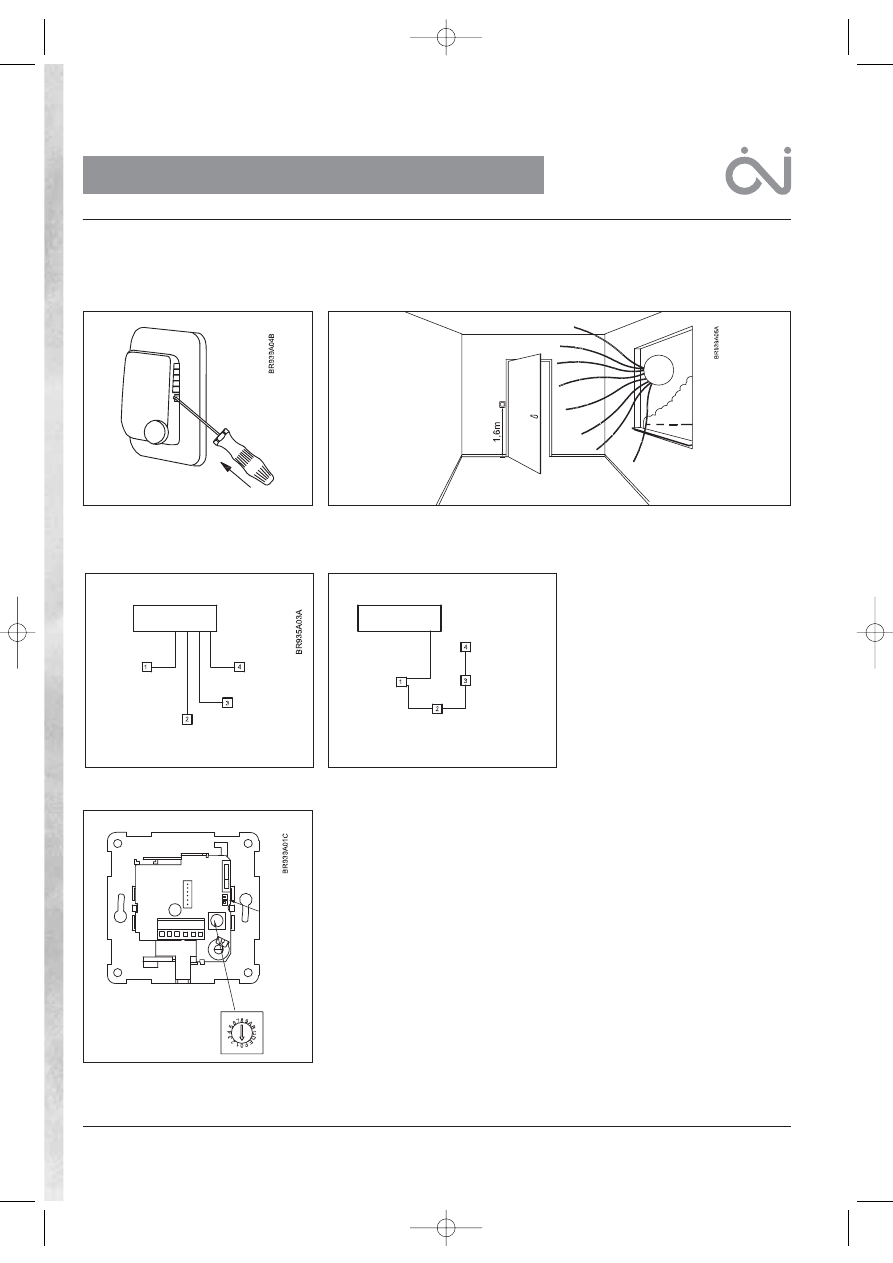
Pod∏àczenie termostatów - magistrala
danych
Do systemu mo˝na pod∏àczyç tylko i wy∏àcznie
termostaty OJ typu WLxx. Sà one przystos-
owane do pod∏àczenia typowym przewodem
instalacyjnym , minimum 2x0,5 mm. Termosta-
ty mo˝na po∏àczyç z Modu∏em G∏ównym tra-
dycyjnym sposobem, w "gwiazd´" ( ka˝dy
termostat pod∏àczany bezpoÊrednio do Modu∏u
G∏ównego), lub wykorzystujàc mo˝liwoÊci
magistrali danych ( do najbli˝szego, sàsiednie-
go termostatu). Modu∏ G∏ówny posiada trzy
pary styków opisanych jako THERMOSTA
BUS, do których mo˝na pod∏àczyç 2-˝y∏owe
przewody od termostatów. Ka˝dy z termosta-
tów mo˝e byç pod∏àczony do dowolnej pary
styków. Ca∏kowita d∏ugoÊç przewodów
przy∏àczeniowych nie mo˝e przekroczyç 300m,
a najwi´ksza d∏ugoÊç przewodu mi´dzy dwo-
ma termostatami - 100m.
Pami´taj, by pod∏àczaç + do + oraz - do -.
WYBIERANIE, KTÓRY TERMOSTAT MA WSPÓ¸PRACOWAå Z KTÓRYM ZAWOREM
TERMOELEKTRYCZNYM
Ka˝dy z termostatów mo˝e wspó∏pracowaç z dowolnym zaworem termoelektrycznym, pod∏àczonym
do jednego z wyjÊç Modu∏u G∏ównego. Po zdj´ciu obudowy, w ka˝dym termostacie widoczny jest
prze∏àcznik, na którym za pomocà Êrubokr´ta, wybieramy numer wyjÊcia, czyli kana∏ termostatu.
Mo˝na wybraç jeden z 14-tu kana∏ów pracy, lub jeden z dwóch kana∏ów specjalnych. Modu∏ G∏ówny
posiada 6 wyjÊç. System mo˝na rozbudowaç a˝ do 14-tu wyjÊç, poprzez do∏àczenie maksymalnie
dwóch Modu∏ów Dodatkowych, z których ka˝dy posiada 4 wyjÊcia. Mo˝na w ten sposób stworzyç
uk∏ad sterujàcy temperaturà a˝ w 14-tu pomieszczeniach.
Prosz´ zwróciç uwag´, ˝e kana∏y od 10 do 14 sà oznaczone na prze∏àczniku jako od A do E.
Termostat ustawiony na kana∏ 1, b´dzie sterowa∏ zaworem termoelektrycznym pod∏àczonym do
wyjÊcia nr 1 Modu∏u G∏ównego. Do wyboru kana∏u termostatu nie jest potrzebne pod∏àczenie zasila-
nia. Kana∏ termostatu mo˝e byç zmieniony w przysz∏oÊci, je˝eli zajdzie taka potrzeba.
Je˝eli dwa termostaty umieszczone w tym samym pomieszczeniu ustawimy na tym samym kanale,
system b´dzie pracowa∏ uwzgl´dniajàc ich Êrednià temperatur´.
Kana∏ 0 :
W ka˝dym nowym termostacie, prze∏àcznik jest zawsze ustawiony na kana∏ 0, wymaga wi´c wybra-
nia kana∏u, by dzia∏a∏ prawid∏owo. Kana∏ 0 jest wybierany w termostatach zegarowych, je˝eli term-
ostat taki ma zarzàdzaç grupà termostatów, a z powodu wygody u˝ytkowania systemu jest umie-
szczony z dala od tych termostatów, np. w kuchni. Wybranie na nim kana∏u 0 oznacza, ˝e czasy i
temperatury na nim wybrane obowiàzujà ca∏à grup´ termostatów, lecz sam termostat zegarowy nie
steruje ˝adnym wyjÊciem.
Kana∏ 15 (F):
Funkcja specjalna. Opis funkcji znajduje si´ w instrukcji u˝ytkowania Modu∏u G∏ównego.
Monta˝ termostatu (rys.2)
Termostat montuje si´ na Êcianie wewn´trznej, w miejscu pozwalajàcym na swobodny przep∏yw
powietrza, na wysokoÊci oko∏o 1,6 m od pod∏ogi. Nale˝y unikaç miejsc bezpoÊrednio nas∏onecznio-
nych oraz Êcian, na które oddzia∏ywujà inne êród∏a ciep∏a.
Rys. 1
Rys. 3
Rys. 5
Rys. 4
Rys. 2
1
Rodzaje termostatów
WLTP-19
Termostat bez regulacji temperatury
WLTA-19
Termostat z regulacjà temperatury
WLTM-19 Termostat z regulacjà temp. i prze∏àcznikiem trybu pracy Auto, Dzieƒ, Noc, Wy∏àczony
WLTD-19 Termostat z regulacjà temp., prze∏àcznikiem trybu pracy Auto, Dzieƒ, Noc, Wy∏àczony, oraz czujnikiem temp. pod∏ogi (max/min).
WLCT-19 Termostat zegarowy, cykl 4 temp w ciàgu doby
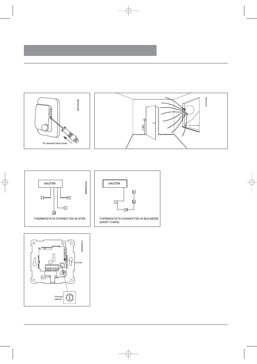
Aby zdjàç przykrywk´ obudowy
Modu∏ G∏ówny
Modu∏ G∏ówny
Termostaty pod∏àczone “w gwiazd´”
(sposób tradycyjny)
Termostaty pod∏àczone szeregowo
(magistrala danych)
Prze∏àcznik
kana∏ów
pracy
Zworka
57445 11/05 (BJ)
57445_11_05 07/12/05 12:03 Side 1
2
Czujnik temperatury minimalnej i maksymalnej pod∏ogi
Termostaty z czujnikiem ograniczajàcym temperatur´ posiadajà
na p∏ytce drukowanej mechanicznà zwork´, pozwalajàcà na
wybór temperatury minimalnej lub maksymalnej pod∏ogi. Je˝eli
wybierzemy ustawienie MAX, temperatura pod∏ogi nie przekro-
czy 27°C, je˝eli wybierzemy MIN, temperatura pod∏ogi nie spa-
dnie poni˝ej 17°C. Dla Modu∏ów G∏ównych typu WLM-1BA oraz
WLM-3BA temperatury te sà niezmienne, chyba ˝e termostat
pracuje w grupie termostatu zegarowego typu WLCT. W takim
przypadku obowiàzujà temperatury MIN i MAX zaprogramowane
na termostacie WLCT, które mo˝na dowolnie zmieniaç. Tempe-
ratury te obowiàzujà wszystkie termostaty z czujnikiem pod∏ogo-
wym, znajdujàce si´ w grupie tego termostatu zegarowego.
Monta˝ pod∏ogowego czujnika temperatury
Ograniczenie temperatury maksymalnej pod∏ogi stosowane jest,
gdy istnieje potrzeba zabezpieczenia pod∏ogi przed przegrza-
niem. Mo˝e byç to niezb´dne w przypadku np. drewnianych
pod∏óg.
Czujnik umieszczamy w miejscu, w którym b´dzie on odczytywa∏
rzeczywistà temperatur´ pod∏ogi, zawsze wewnàtrz ogrzewanej
pod∏ogi.
Ograniczenie temperatury minimalnej pod∏ogi stosujemy, gdy
chcemy by by∏a ona ciep∏a, niezale˝nie od temperatury w pomie-
szczeniu. Przyk∏adem mogà byç p∏ytki w ∏azience lub na base-
nie, które szybciej wysychajà, gdy pod∏oga jest ciep∏a. Czujnik
umieszczamy w miejscu, w którym mierzy on rzeczywistà tem-
peratur´ pod∏ogi, zawsze w ogrzewanym pod∏o˝u.
W celu ∏atwej wymiany czujników, zaleca si´ montowaç je w rur-
ce umieszczonej pomi´dzy dwoma rurami grzejnymi.
Wewn´trzny koniec rurki nale˝y zaÊlepiç, drugim zaÊ koƒcem
wyprowadzamy przewód czujnika do Êciany pomieszczenia.
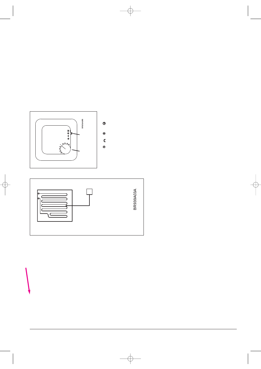
Czujnik pod∏àczamy typowym przewodem instalacyjnym. Jego
d∏ugoÊç nie mo˝e przekroczyç 50 m.
Monta˝ pod∏ogowego czujnika temperatury maksymalnej i minimalnej- termostaty typu WLTD i WLCT
Zworka zwarta: ograniczenie temp. maksymalnej
Zworka rozwarta: ograniczenie temp. minimalnej
Umiejscowienie zworki: patrz rys. 5
WLTM-19: Zastosowanie zewn´trznego czujnika temperatury pokojowej
The description doe's not match the fig. number. I don't understand the meaning of
that statement.
Zworka zamontowana: zewn´trzny czujnik temperatury w pomieszczeniu
Zworka usuni´ta: wbudowany czujnik temperatury w pomieszczeniu
OJ Electronics A/S
Stenager 13B · DK-6400 Sønderborg · Denmark
Tel +45 73 12 13 14 · Fax +45 73 12 13 13
oj@oj.dk · www.oj.dk
Wybieranie trybu pracy termostatu
Ustawianie temperatury w pomieszczeniu
Modu∏ G∏ówny dostarczany jest z zaprogramowanymi fabrycznie wartoÊciami temperatur, które sà obowiàzujàce dla wszystkich nie zegarowych term-
ostatów pracujàcych w systemie. W Modu∏ach G∏ównych typu WLM-1BA oraz WLM-3BA, temperatura dzienna (DAY) wynosi 20°C, a temperatura nocna
(NIGHT) 15°C.
W Modu∏ach G∏ównych z wyÊwietlaczem, typu WLM-1FS oraz WLM-3FS, temperatury DAY, NIGHT oraz OFF mo˝na dowolnie zmieniaç.
Automatyczne prze∏àczanie mi´dzy temperaturami DAY oraz NIGHT mo˝na realizowaç za pomocà oddzielnego zegara sterujàcego, pod∏àczonego do
Modu∏u G∏ównego, lub stosujàc termostat zegarowy typu WLCT, przyporzàdkowujàc mu termostaty niezegarowe, jako jego grup´. W systemie mo˝e pra-
cowaç dwa lub wi´cej termostatów zegarowych, a ka˝dy z nich mo˝e mieç swojà w∏asnà grup´ termostatów niezegarowych.
Na ka˝dym z termostatów typu WLTA, WLTM oraz WLTD, mo˝na lokalnie zmniejszyç lub zwi´kszyç temperatur´ w jego pomieszczeniu o + - 4°C, w sto-
sunku do temperatury zaprogramowanej w Module G∏ównym. S∏u˝y do tego proste pokr´t∏o, umieszczone w tych termostatach.
Je˝eli termostaty typu WLTM-19 lub WLTD-19 zosta∏y przydzielone do grupy termostatu zegarowego, to w przypadku wybrania umieszczonym na nich
prze∏àcznikiem trybu automatycznego, temperatura w pomieszczeniu b´dzie ustawiana tak, jak zaprogramowano w termostacie zegarowym, a nie tak jak
w Module G∏ównym. Jednak równie˝ w takim przypadku mo˝na miejscowo doregulowaç temperatur´ w pomieszczeniu o + - 4°C.
W Modu∏ach G∏ównych typu WLM-1FS oraz WLM-3FS, zaprogramowanie nowych temperatur powoduje, ˝e stajà si´ one obowiàzujàce dla wszystkich
termostatów, jednak lokalnie mo˝na je zmniejszyç lub zwi´kszyç o 4°C w ka˝dym z pomieszczeƒ.
Termostaty typu WLTM-19 oraz WLTD-19 posiadajà prze∏àcznik (patrz rys.6), który s∏u˝y do
r´cznego wyboru trybu ich pracy. Mo˝na wybraç jeden z czterech trybów pracy: Auto, Dzieƒ,
Noc, Wy∏àczony ( OFF).
Auto: Termostat realizuje temperatur´ ustawionà na Module G∏ównym, lub je˝eli nale˝y do
grupy termostatów termostatu zegarowego, b´dzie realizowa∏ zaprogramowany na nim cykl
czasu i temperatury.
Day: Termostat b´dzie kontrolowa∏ temperatur´ w pomieszczeniu zgodnie z temperaturà
dziennà, ustawionà na Module G∏ównym (ustawienie fabryczne 20 C).
Night: Termostat b´dzie kontrolowa∏ temperatur´ w pomieszczeniu zgodnie z temperaturà
nocnà, ustawionà na Module G∏ównym (ustawienie fabryczne 15 C).
OFF: Termostat b´dzie kontrolowa∏ temperatur´ w pomieszczeniu zgodnie z temperaturà
OFF, ustawionà na Module G∏ównym (ustawienie fabryczne 5 C). Ten tryb stosuje si´ jako
"zabezpieczenie przed zamarzaniem", je˝eli pomieszczenie nie b´dzie u˝ytkowane przez
d∏ugi czas.
Termostaty typu WLTM-19 oraz WLTD-19 polecane sà szczególnie do pokoi goÊcinnych oraz do
innych rzadko u˝ytkowanych pomieszczeƒ, gdy˝ pozwalajà w prosty sposób zmieniç ustawienia
automatyczne.
Rys. 6
Rys. 7
Prze∏àcznik
przesuwny
Pokr´t∏o
regulacyjne
Czujnik temp. pod∏ogi,
max 50m
57445_11_05 07/12/05 12:03 Side 2
Type UUU-XX
I N S T R U C T I O N S
3
Waterline thermostats type WL…
I N S T R U C T I O N S
THERMOSTATS – BUS CONNECTION
Only OJ thermostats type WLxx that are
suitable for 2 wire communication can be used.
Standard installation cable, minimum 2 x 0.25
mm
2
can be used. The thermostats can be
connected in the conventional star wiring
format, or in a bus connected mode (Daisy
chain). The master has 3 sets of terminals
marked THERMOSTAT BUS that can be used
for connecting the 2-wire signal from the
thermostats. There are 3 identical sets of
terminals for convenient installation. Any
thermostat can be connected to any pair of
terminals. The total length of the 2-wire system
can be up to 300 m with a maximum length of
100 m between any 2 thermostats.
Remember to connect + to + and – to – .
SETTING UP WHICH THERMOSTAT SHOULD WORK WITH WHICH THERMAL ACTUATOR
Each thermostat can be selected to operate a specific output which in turn controls the thermal
actuators on the manifold. Under the front cover of the thermostat, a selector can be accessed, and
the number of its output (its CH channel) can be set with a screwdriver. Up to 14 channels can be
set on the selector, and there are two auxiliary channels with special functions. A WLM master has 6
outputs and additional slave modules each with 4 outputs can be connected creating a system of 14
individual zones.
Please note that channels 10 to 14 are marked as A through E on the selector.
A thermostat set for CH1 will activate the thermal actuator connected to output 1 on the master. The
channel number can be selected without any power connected to the system. The channel of the
thermostat can be changed afterwards if needed. If two thermostats are placed in the same room and
set to the same channel, the temperature control will work according to the average temperature of
both thermostats.
Channel 0:
Each thermostat is delivered with the switch in position 0 ensuring that it must be set to operate
correctly. Channel 0 can also be used for a clock thermostat controlling a group of thermostats where
the control position could be somewhere central, e.g. the kitchen, rather than in the area where the
thermostats are installed. Setting it to Ch 0 means that times and temperatures are set on the WLCT
for the group, but that the WLCT will not control a specific output itself.
Channel 15 (F):
Special function. Further instructions in the instruction for the master.
Mounting of thermostat (fig. 2)
The thermostat is used for comfort temperature control in rooms. The thermostat is mounted on an
internal wall with free air circulation about 1.6 m above the floor. Draught, direct sunlight, or any other
direct heating source must be avoided.
Fig. 1
Fig. 3
Fig. 5
Fig. 4
Fig. 2
Product programme
WLTP-19 Thermostat tamper proof
WLTA-19
Thermostat with adjustment
WLTM-19 Thermostat with adjustment and mode switch Auto, Day, Night, OFF
WLTD-19 Thermostat with adjustment, mode switch Auto, Day, Night, OFF and limit sensor
WLCT-19 Thermostat with 4-event clock
57445_11_05 07/12/05 12:03 Side 3
4
Limit Sensor
Thermostats with a limit sensor have a mechanical jumper on the
printed circuit board allowing the limitation to be set for MIN. or
MAX. temperature regulation. If set for MAX., it will have a
temperature setting of 27°C. Set for MIN., it has a setting of 17°C.
These temperature are fixed when used with masters WLM-1BA
or WLM-3BA unless the thermostat has been allocated to a zone
group controlled by a WLCT clock thermostat. In this case, the
limit settings can be increased or decreased by accessing the
clock thermostat. The limits then set will apply to all relevant
thermostats with limit sensors belonging to that group. If the
master WLM-1FS or WLM-3FS is used, the limit settings can be
changed through the programming buttons on the master.
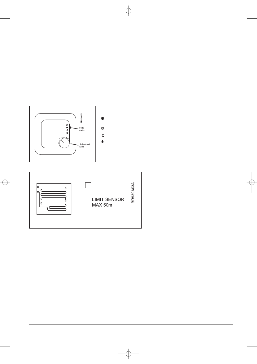
Mounting of limitation sensor
Max. temperature limitation is used to protect the floor area
from becoming too warm. This may be required if special floor
surfaces (real wood) are used. The sensor should be positioned
where it can read the true temperature of the floor and should
always be within the heated area.
Min. temperature limitation is used to keep a floor surface
warm, irrespective of room temperature. For example, water on
tiled bathrooms or pool areas with dry more quickly if the floor
surface is kept warm. The sensor should be positioned where it
can read the true temperature of the floor and should always be
within the heated area.
For easy replacement we recommend that all floor sensors are
mounted in a tube which is placed between 2 heating pipes. The
inner end of the tube should be sealed, and the sensor cable
brought back to the wall edge. If required, the sensor cable can
be extended up to 50 m with standard installation cable.
Mounting of limit sensor type WLTD and WLCT
Jumper connected: max. limitation
Jumper removed : min. limitation
Location of jumper see fig. 3
WLTM-19: Use of external room sensor
A remote room sensor can be used instead of the built-in sensor by connecting the jumper across the two pin bridge on the printed circuit board under the
thermostat cover. From factory the jumper is "parked" on one pin. Location of jumper see fig. 3.
Jumper connected: External room sensor
Jumper removed: Built-in room sensor
OJ Electronics A/S
Stenager 13B · DK-6400 Sønderborg · Denmark
Tel +45 73 12 13 14 · Fax +45 73 12 13 13
oj@oj.dk · www.oj.dk
Setting of thermostat operating mode
Setting of Room Temperature
The master is supplied with default temperature settings which are used by all non clock thermostats that are connected to the system. In Master WLM-1BA
& WLM-3BA, the DAY temperature setting is fixed at 20°C and the NIGHT temperature is fixed at 15°C.
In Master WLM-1FS & WLM-3FS, the DAY, NIGHT and OFF default temperatures are adjustable through the display.
Automatic switching between DAY and NIGHT temperatures is done by either connecting a separate timing device to the master, or using a WLCT clock
thermostat and allocating other non clock thermostats as part of its group. It is possible to have two or more clock thermostats in the system, with each one
having its own group of non clock thermostats.
Each WLTA, WLTM or WLTD thermostat is locally adjustable with its own adjustment knob. With this knob the temperature setting from the Master can be
increased or decreased by 4°C for that specific room.
If the WLTM-19 or WLTD-19 thermostat has been allocated to a clock controlled group, then when AUTOMATIC mode has been chosen with the built-in
slide switch, the temperature settings will be as programmed in the clock thermostat and not in the master, but the same local ±4°C adjustment is available.
On the Master WLM-1FS and WLM-3FS, if the temperature setting is changed, then the default temperature for all the rooms is changed, but the local
adjustment can still increase or decrease this new setting by ±4°C. Turn the knob clockwise to increase the temperature.
Setting of Thermostat Operating Mode
Thermostats type WLTM-19 and WLTD-19 have a slide switch (see fig. 6) for selecting the mode of
operation of the thermostat. Four different modes can be selected: Auto, Day, Night and OFF.
Auto: The thermostat will follow the temperature settings of the master, or if the thermostat
belongs to a zone group using a WLCT clock thermostat, it will follow the automatic
sequence of temperatures and timings set in the WLCT.
Day: It will control the room temperature according to the (DAY) setting defined in the master
(typically 20°C).
Night: It will control the room temperature according to the (NIGHT) setting defined in the
master (typically 15°C).
OFF: It will control the room temperature according to the (OFF) setting defined in the master
(typically 5°C). This setting is intended to be a ”frost protection” mode and is used if the
room is to be left unoccupied for long periods.
WLTM-19 & WLTD-19 are recommended for guest rooms and other infrequently used rooms, as
they allow simple override of the automatic timing sequence.
Fig. 6
Fig. 7
57445_11_05 07/12/05 12:03 Side 4
Wyszukiwarka
Podobne podstrony:
Glowice termostatyczne typu RAW
Termostabilna B amylaza
Lekcja kliniczna 2 VI rok WL
Cukrzyca typu 1
3 Cukrzyca typu LADA i MODY
Vrok WL Seminarium 1 wrodzone wady serca materialy 2
Wł wodne
Charakterystyka odpowiedzi immunologicznej typu GALT faza indukcji
AKCJA Z UŻYCIEM PASA RATOWNICZEGO TYPU WĘGORZ
Stale typu TWIP
Lekcja kliniczna nr 2 VI rok WL
809 karty haribo typu EPE 3
Opel CorsaB termostat x10xe
BŁOTNIKI PRZEDNIE DO CIĄGNIKÓW Z MOSTEM NAPĘDOWYM 822 23000020 (TYPU (2)
instrukcja bhp przy obsludze wiszacego odsysacza spalin typu ow
elektroniczny termostat
więcej podobnych podstron