02–10–1
02
SUSPENSION
SECTION
02–10
Toc of SCT
GENERAL PROCEDURES . . . . 02-10
WHEEL ALIGNMENT . . . . . . . . 02-11
FRONT SUSPENSION . . . . . . . 02-13
REAR SUSPENSION . . . . . . . . 02-14
TECHNICAL DATA . . . . . . . . . 02-50
SERVICE TOOLS. . . . . . . . . . . 02-60
Toc of SCT
02–10
GENERAL PROCEDURES
PRECAUTION (SUSPENSION) . . . . . . . . 02–10–1
Wheels and Tires
Removal/installation . . . . . . . . . . . . . . 02–10–1
Suspension Links
Removal/installation . . . . . . . . . . . . . . 02–10–1
Power Steering Components
Removal/installation . . . . . . . . . . . . . . 02–10–1
End of Toc
PRECAUTION (SUSPENSION)
A3U021001013W01
Wheels and Tires Removal/installation
1. The removal and installation procedures for the wheels and tires are not mentioned in this section. When a
wheel is removed, retighten it to 89—117 N·m {9—12 kgf·m, 66—86 ft·lbf}.
Suspension Links Removal/installation
1. Tighten any part of the suspension that uses rubber bushings only after the vehicle has been lowered and
unloaded.
Note
•
Unloaded ... Fuel tank is full. Engine coolant and engine oil are at specified levels. Spare tire, jack and
tools are in designated positions.
Power Steering Components Removal/installation
1. If any power steering fluid line has been disconnected anytime during the procedure, add ATF M-
III
or
equivalent (e.g. Dexron
®
III
), bleed the fluid line, and inspect for leakage after the procedure has been
completed.
End Of Sie
1712‑1U‑01G(02‑10).fm 1 ページ 2001年6月29日 金曜日 午前9時53分
WHEEL ALIGNMENT
02–11–1
02–11
02–11
WHEEL ALIGNMENT
WHEEL ALIGNMENT
PRE-INSPECTION . . . . . . . . . . . . . . . . 02–11–1
FRONT WHEEL ALIGNMENT . . . . . . . . 02–11–1
Specification (Unloaded)*1 . . . . . . . . . 02–11–1
Maximum Steering Angle Adjustment . 02–11–1
Camber and Caster Adjustment . . . . . . 02–11–2
Total Toe-in Adjustment . . . . . . . . . . . . 02–11–2
REAR WHEEL ALIGNMENT . . . . . . . . . . 02–11–3
Specification (Unloaded)*1 . . . . . . . . . . 02–11–3
Total Toe-in Adjustment . . . . . . . . . . . . 02–11–3
End of Toc
WHEEL ALIGNMENT PRE-INSPECTION
A3U021101013W01
1. Inspect the tire inflation, and adjust to the recommended pressure as necessary.
2. Inspect the front wheel for bearing play and correct it if necessary. (See 03–11–1 Wheel Bearing Play
Inspection.)
3. Inspect the wheel and tire runouts. (See 02–50–1 SUSPENSION TECHNICAL DATA.)
4. Inspect the ball joints and steering linkage for excessive looseness.
5. Shake the vehicle to inspect the operation of the shock absorbers.
Note
•
The vehicle must be on level ground and unloaded.
•
Unloaded ... Fuel tank is full. Engine coolant and engine oil are at specified levels. Spare tire, jack and
tools are in designated positions.
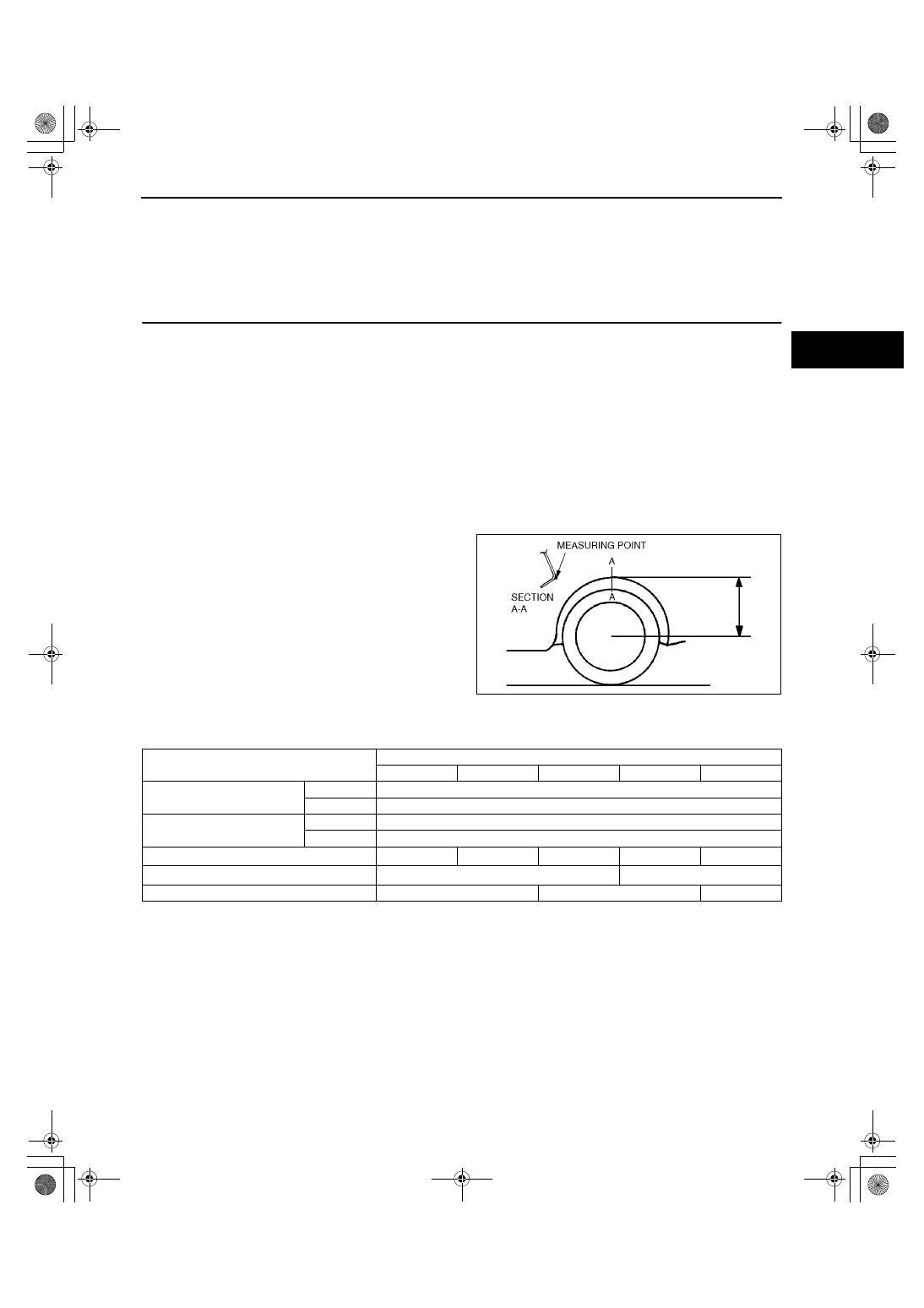
6. Measure the height from the center of the wheel
to the fender brim. The difference between the left
and right measurement must not exceed 10 mm
{0.39 in}.
End Of Sie
FRONT WHEEL ALIGNMENT
A3U021101015W01
Specification (Unloaded)*
1
*
1
: Engine coolant and engine oil are at specified levels. Spare tire, jack and tools are in designated positions.
*
2
: Difference between left and right must not exceed 1
°°°°
30'.
Maximum Steering Angle Adjustment
1. Loosen the tie-rod end locknuts.
2. Remove the steering gear boot clamp.
Z3U0211W001
Item
Fuel gauge indication
Empty
1/4
1/2
3/4
Full
Total toe-in
(mm {in})
2
±
4 {0.08
±
0.16}
(degree)
0
°
12'
±
24'
Maximum steering angle
Inner
37
°±
3
°
Outer
33
°±
3
°
Caster angle*
2
1
°
46'
±
1
°
1
°
49'
±
1
°
1
°
51'
±
1
°
1
°
53'
±
1
°
1
°
56'
±
1
°
Camber angle*
2
-0
°
48'
±
1
°
-0
°
49'
±
1
°
Kingpin angle (reference value)
12
°
34'
12
°
35'
12
°
36'
1712‑1U‑01G(02‑11).fm 1 ページ 2001年6月29日 金曜日 午前9時54分
WHEEL ALIGNMENT
02–11–2
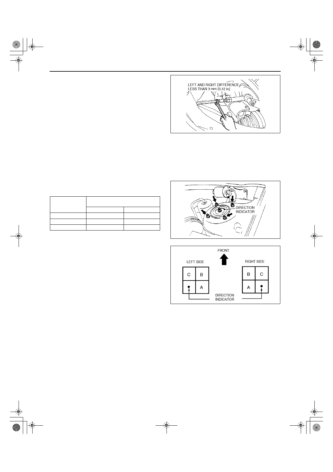
3. Turn the left and right tie rods to equalize the
length L.
Maximum left/right difference
3 mm {0.12 in}
Note
•
Turn the tie rods equally.
4. Turn the tie rod to provide the correct maximum
steering angle.
5. Tighten the tie-rod end locknuts.
Tightening torque
68.7—98.0 N·m {7.0—10.0 kgf·m, 50.7—72.3 ft·lbf}
6. Verify that the boot is not twisted, and install the boot clamp.
7. Adjust the toe-in after adjusting the steering angle.
Camber and Caster Adjustment
1. Jack up the front of the vehicle and support it on safety stands.
2. Remove the mounting block nuts.
3. Push the mounting block downward, and turn it to
the desired position.
4. Install and tighten the mounting nuts to the
specified torque.
Tightening torque
47—62 N·m {4.7—6.4 kgf·m, 34—46 ft·lbf}
Total Toe-in Adjustment
1. Center the steering wheel and confirm that the vehicle wheels/tires are pointing straight.
2. Remove the steering gear boot clamp.
3. Loosen the left and right tie rod locknuts and turn the tie rods equally. Both tie rods are right threaded, so
turning the right tie rod toward the front of the vehicle and the left toward the rear increases toe-in.
Note
•
Turning both tie rods one complete turn changes toe-in by about 6 mm {0.24 in} (0
°°°°
36').
4. Tighten the tie rod locknuts to the specified torque.
Tightening torque
68.7—98.0 N·m {7.0—10.0 kgf·m, 50.7—72.3 ft·lbf}
5. Verify that the boot is not twisted, and install the boot clamp.
End Of Sie
Z3U0211W002
Direction
indicator
position
Adjustment valve from original
position
Camber angle
Caster angle
A
+30'
0
°
B
+30'
+30'
C
0
°
+30'
Z3U0211W003
Z3U0211W004
1712‑1U‑01G(02‑11).fm 2 ページ 2001年6月29日 金曜日 午前9時54分
WHEEL ALIGNMENT
02–11–3
02–11
REAR WHEEL ALIGNMENT
A3U021101016W01
Specification (Unloaded)*
1
*
1
: Engine coolant and engine oil are at specified levels. Spare tire, jack and tools are in designated positions.
Adjust to the median when carrying out wheel alignment.
*
2
: Difference between left and right must not exceed 1
°°°°
30'.
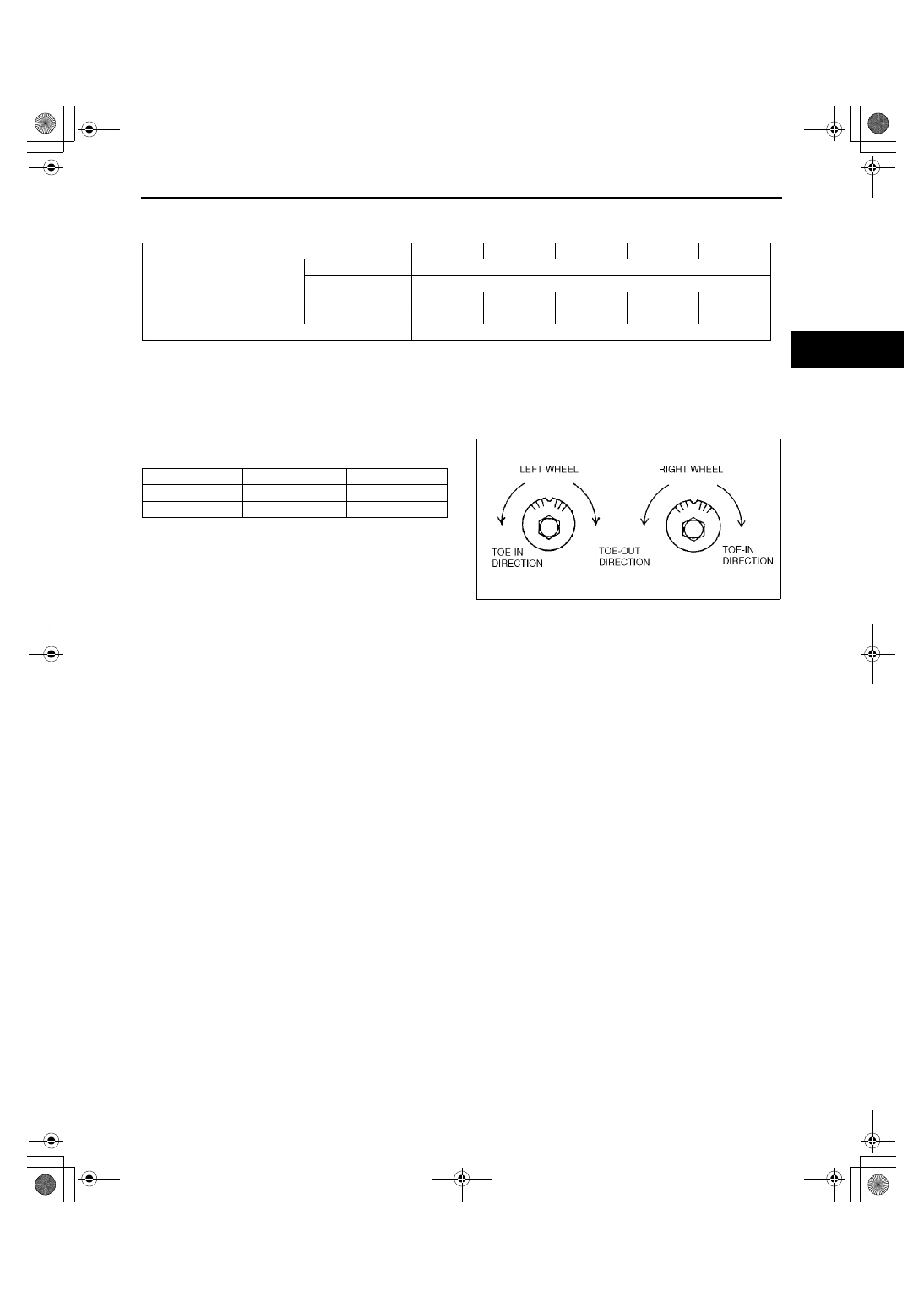
Total Toe-in Adjustment
1. Loosen the cam nut on the lateral link.
2. Turn the adjusting cam bolt as indicated to adjust
the toe-in.
Note
•
Turning the adjusting cam bolt one complete
turn changes the toe-in about 3.0 mm {0.12
in} (0
°°°°
18').
3. Tighten the cam nut.
Tightening torque
50—69 N·m {5.1—7.1 kgf·m, 37—50 ft·lbf}
End Of Sie
Fuel gauge indication
Empty
1/4
1/2
3/4
Full
Total toe-in
(mm {in})
2
±
4 {0.08
±
0.16}
(degree)
0
°
12'
±
24'
Camber angle*
2
(reference value)
14, 15 inch wheel
–0
°
23'
±
1
°
–0
°
25'
±
1
°
–0
°
27'
±
1
°
–0
°
29'
±
1
°
–0
°
31'
±
1
°
16 inch wheel
–0
°
27'
±
1
°
–0
°
29'
±
1
°
–0
°
31'
±
1
°
–0
°
32'
±
1
°
–0
°
34'
±
1
°
Thrust angle (reference value)
0
°±
48'
Left wheel
Right wheel
Toe-in direction
Counterclockwise
Clockwise
Toe-out direction
Clockwise
Counterclockwise
Z3U0211W005
1712‑1U‑01G(02‑11).fm 3 ページ 2001年6月29日 金曜日 午前9時54分
FRONT SUSPENSION
02–13–1
02–13
02–13
FRONT SUSPENSION
FRONT SUSPENSION LOCATION
INDEX . . . . . . . . . . . . . . . . . . . . . . . . . . 02–13–1
FRONT SHOCK ABSORBER AND COIL
SPRING REMOVAL/INSTALLATION . . 02–13–2
Piston Rod Nut Removal Note . . . . . . . 02–13–3
Coil Spring Installation Note. . . . . . . . . 02–13–3
Front Shock Absorber and Spring
Installation Note . . . . . . . . . . . . . . . . . 02–13–4
FRONT SHOCK ABSORBER
INSPECTION . . . . . . . . . . . . . . . . . . . . . 02–13–4
FRONT SHOCK ABSORBER
DISPOSAL. . . . . . . . . . . . . . . . . . . . . . . 02–13–4
FRONT LOWER ARM
REMOVAL/INSTALLATION . . . . . . . . . 02–13–5
Dust Boot Removal Note . . . . . . . . . . . 02–13–5
Lower Arm Bushing (Front) Removal
Note . . . . . . . . . . . . . . . . . . . . . . . . . . 02–13–5
Lower Arm Bushing (Rear) Removal
Note . . . . . . . . . . . . . . . . . . . . . . . . . . 02–13–6
Lower Arm Bushing (Rear) Installation
Note. . . . . . . . . . . . . . . . . . . . . . . . . . . 02–13–6
Lower Arm Bushing (Front) Installation
Note. . . . . . . . . . . . . . . . . . . . . . . . . . . 02–13–6
Dust Boot Installation Note . . . . . . . . . . 02–13–7
FRONT LOWER ARM INSPECTION . . . . 02–13–7
FRONT STABILIZER
REMOVAL/INSTALLATION . . . . . . . . . . 02–13–7
Stabilizer Bracket Installation Note . . . . 02–13–8
STABILIZER CONTROL LINK (FRONT)
INSPECTION . . . . . . . . . . . . . . . . . . . . . 02–13–8
FRONT CROSSMEMBER
REMOVAL/INSTALLATION . . . . . . . . . . 02–13–8
Crossmember Component Removal
Note. . . . . . . . . . . . . . . . . . . . . . . . . . . 02–13–9
TRANSVERSE MEMBER (ZM (ATX), FS)
REMOVAL/INSTALLATION . . . . . . . . . . 02–13–9
FRONT STRUT BAR
REMOVAL/INSTALLATION . . . . . . . . . . 02–13–10
End of Toc
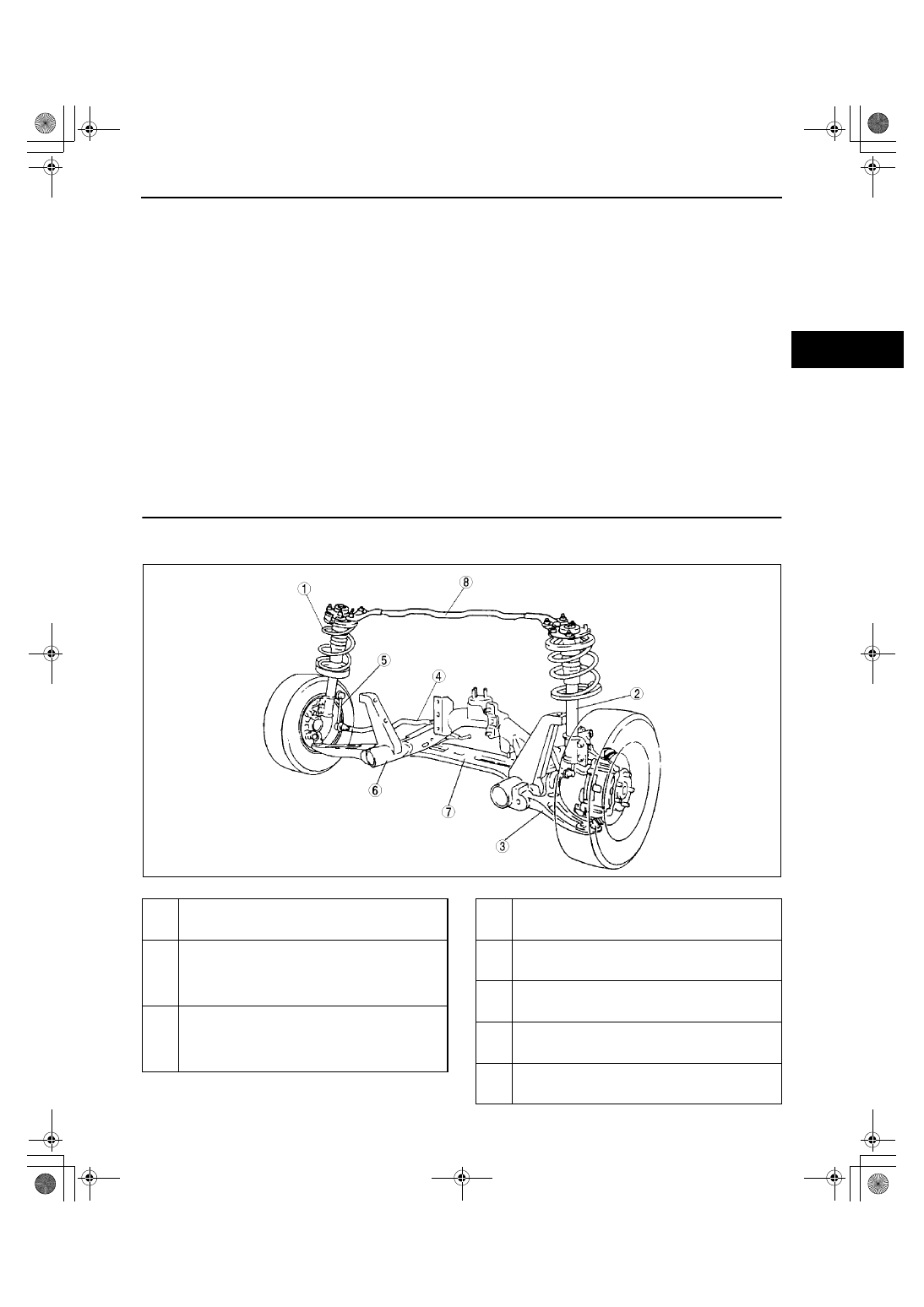
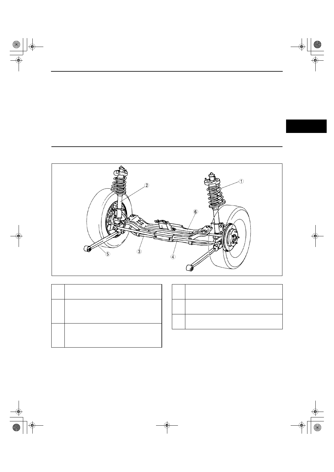
FRONT SUSPENSION LOCATION INDEX
A3U021301015W01
.
A3U0213W001
1
Front shock absorber and coil spring
(See 02–13–2 FRONT SHOCK ABSORBER AND
COIL SPRING REMOVAL/INSTALLATION)
2
Front shock absorber
(See 02–13–4 FRONT SHOCK ABSORBER
INSPECTION)
(See 02–13–4 FRONT SHOCK ABSORBER
DISPOSAL)
3
Front lower arm
(See 02–13–5 FRONT LOWER ARM REMOVAL/
INSTALLATION)
(See 02–13–7 FRONT LOWER ARM
INSPECTION)
4
Front stabilizer
(See 02–13–7 FRONT STABILIZER REMOVAL/
INSTALLATION)
5
Stabilizer control link
(See 02–13–8 STABILIZER CONTROL LINK
(FRONT) INSPECTION)
6
Front crossmember
(See 02–13–8 FRONT CROSSMEMBER
REMOVAL/INSTALLATION)
7
Transverse member
(See 02–13–9 TRANSVERSE MEMBER (ZM
(ATX), FS) REMOVAL/INSTALLATION)
8
Front strut bar (5HB only)
(See02–13–10 FRONT STRUT BAR REMOVAL/
INSTALLATION)
1712‑1U‑01G(02‑13).fm 1 ページ 2001年6月30日 土曜日 午前10時2分
FRONT SUSPENSION
02–13–2
End Of Sie
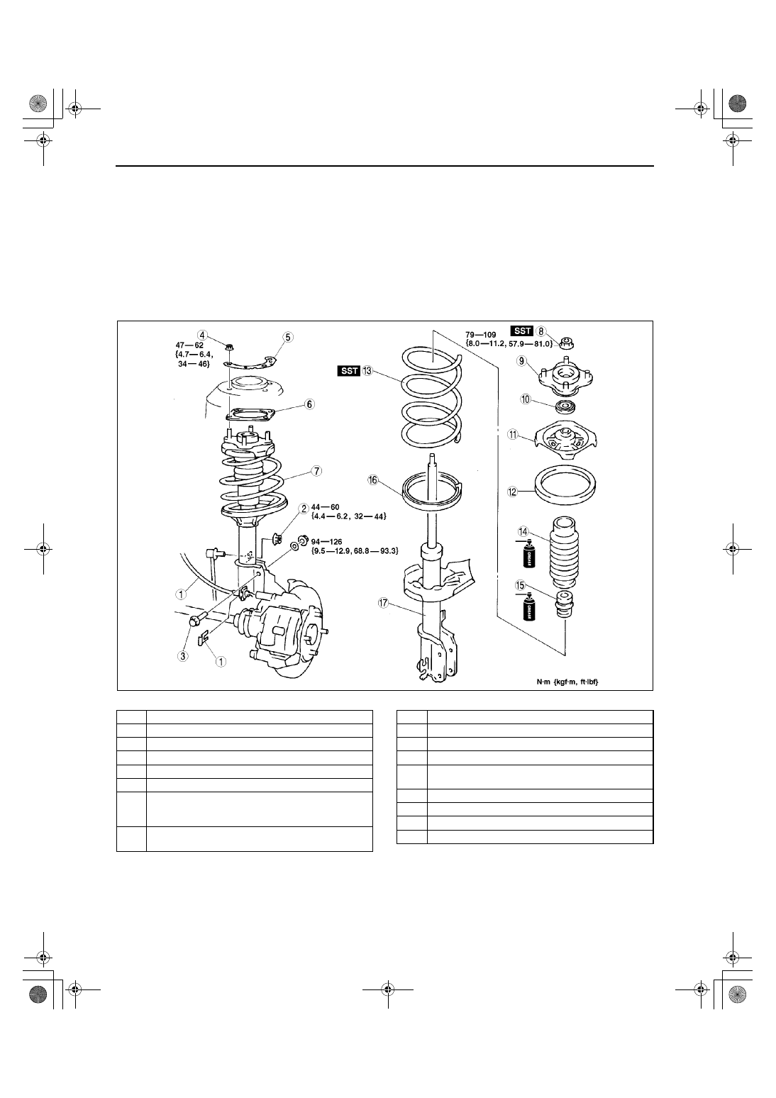
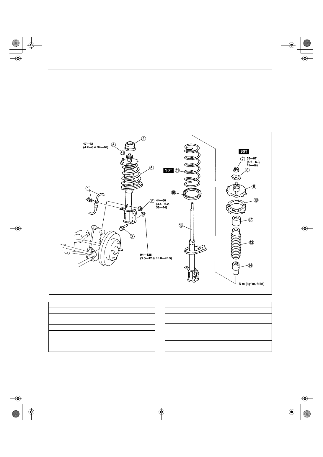
FRONT SHOCK ABSORBER AND COIL SPRING REMOVAL/INSTALLATION
A3U021304910W01
Caution
••••
Performing the following procedures without first removing the ABS wheel-speed sensor may
possibly cause an open circuit in the harness if it is pulled by mistake. Before performing the
following procedures, remove the ABS wheel-sensor (axle side) and set it to an appropriate place
where the sensor will not be pulled by mistake while servicing the vehicle.
1. Remove in the order indicated in the table.
2. Install in the reverse order of removal.
3. Inspect the front wheel alignment.
•
If not as specified, adjust the front wheel alignment. (See 02–11–1 FRONT WHEEL ALIGNMENT.)
.
Z3U0213W002
1
Clip and brake hose
2
Nut (Stabilizer control link)
3
Shock absorber bolt
4
Nut
5
Stiffener
6
Sheet
7
Front shock absorber and spring
(See 02–13–4 Front Shock Absorber and Spring
Installation Note)
8
Piston rod nut
(See 02–13–3 Piston Rod Nut Removal Note)
9
Mounting rubber
10
Bearing
11
Upper spring seat
12
Upper spring seat rubber
13
Coil spring
(See 02–13–3 Coil Spring Installation Note)
14
Dust Boot
15
Bound stopper
16
Lower spring seat rubber
17
Shock absorber
1712‑1U‑01G(02‑13).fm 2 ページ 2001年6月30日 土曜日 午前10時2分
FRONT SUSPENSION
02–13–3
02–13
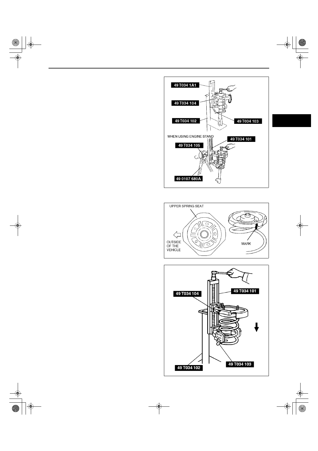
Piston Rod Nut Removal Note
1. Protect the coil spring using a piece of cloth, then
set the SSTs.
Warning
••••
Removing the piston rod nut is
dangerous. The shock absorber and
spring could fly off under tremendous
pressure and cause serious injury or
death. Secure the shock absorber in the
SSTs before removing the coil spring nut.
2. Compress the coil spring using the SSTs, and
remove the piston rod nut.
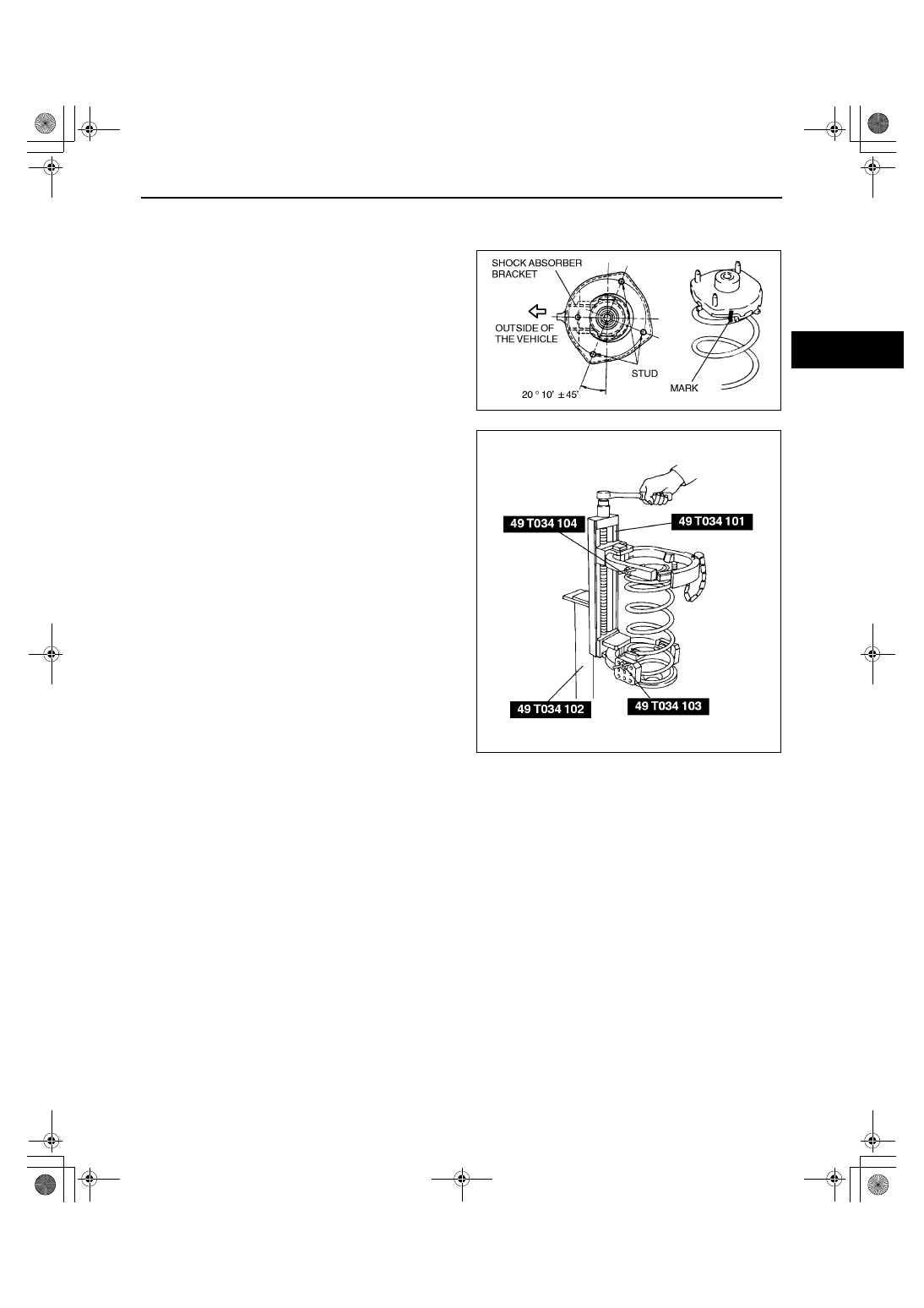
Coil Spring Installation Note
1. Temporarily install the coil spring, upper spring
seat rubber and upper spring seat on the shock
absorber so that the lower end of the coil spring is
seated on the step of the lower spring seat.
2. Mark the coil spring, upper spring seat rubber and
upper spring seat for proper installation as shown
in the figure.
3. Align the marks of the coil spring, upper spring
seat rubber and upper spring seat. Protect the
coil spring and upper seat spring using a piece of
cloth, then set the SSTs.
4. Compress the coil spring using the SSTs.
5. Install the lower spring seat rubber on the lower
spring seat.
6. Install the shock absorber so that the lower end of
the coil spring is seated on the step of the lower
spring seat.
7. Make sure that the marks on the shock absorber
and upper spring seat are aligned.
8. Install the bearing, mounting rubber, and piston
rod nut as shown in the figure, then remove the
SSTs.
Z3U0213W003
Z3U0213W004
Z3U0213W005
1712‑1U‑01G(02‑13).fm 3 ページ 2001年6月30日 土曜日 午前10時2分
FRONT SUSPENSION
02–13–4
Piston rod nut tightening torque
79—109 N·m {8.0—11.2 kgf·m, 57.9—81.0 ft·lbf}
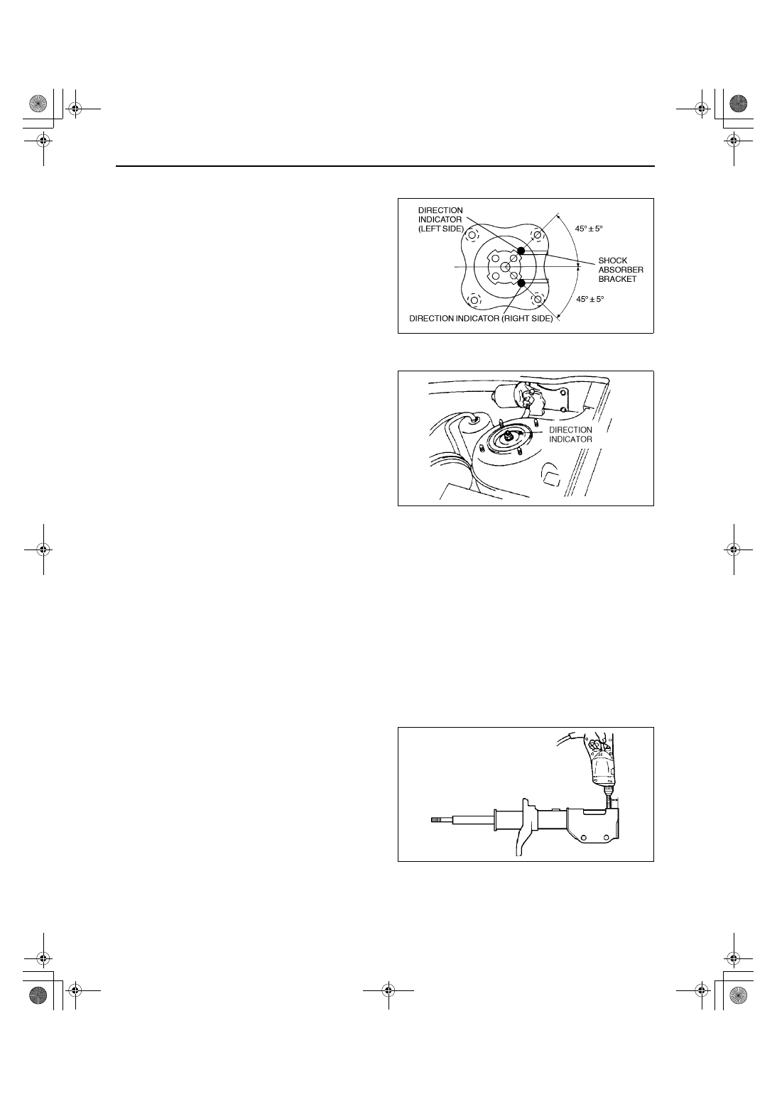
Front Shock Absorber and Spring Installation Note
1. Face the mounting block direction indicator
toward the rear outboard position, and install the
shock absorber.
End Of Sie
FRONT SHOCK ABSORBER INSPECTION
A3U021334700W01
1. Remove the front shock absorber from the vehicle.
2. Inspect for damage and oil leakage.
3. Inspect the rubber bushing for deterioration and wear.
4. Compress and extend the shock piston at least 3 times. Verify that the operational force does not change and
that there is no unusual noise.
(1) Compress the shock absorber piston and release it.
(2) Verify that the piston extends fully at a normal speed.
•
If not as specified, replace the shock absorber.
End Of Sie
FRONT SHOCK ABSORBER DISPOSAL
A3U021334700W02
Warning
••••
Whenever drilling into a shock absorber, wear protective eye wear. The gas in the shock absorber
is pressurized, and could spray metal chips into the eyes and face when drilling.
1. Clamp a shock absorber flat or with the piston downwards.
2. Drill a 2—3 mm {0.08—0.11 in} hole at a point
20—30 mm {0.8—1.1 in} from the bottom of the
tube, so that the gas can escape.
3. Turn the hole downwards.
4. The oil can be collected by moving the piston rod
several times up and down and cutting the tube at
the end.
5. Dispose of waste oil according to the waste
disposal law.
Note
•
Shock absorber gas is nitrogen gas.
•
Shock absorber oil is mineral oil.
End Of Sie
X3U213WA4
Z3U0213W006
Z3U0213W007
1712‑1U‑01G(02‑13).fm 4 ページ 2001年6月30日 土曜日 午前10時2分
FRONT SUSPENSION
02–13–5
02–13
FRONT LOWER ARM REMOVAL/INSTALLATION
A3U021334300W01
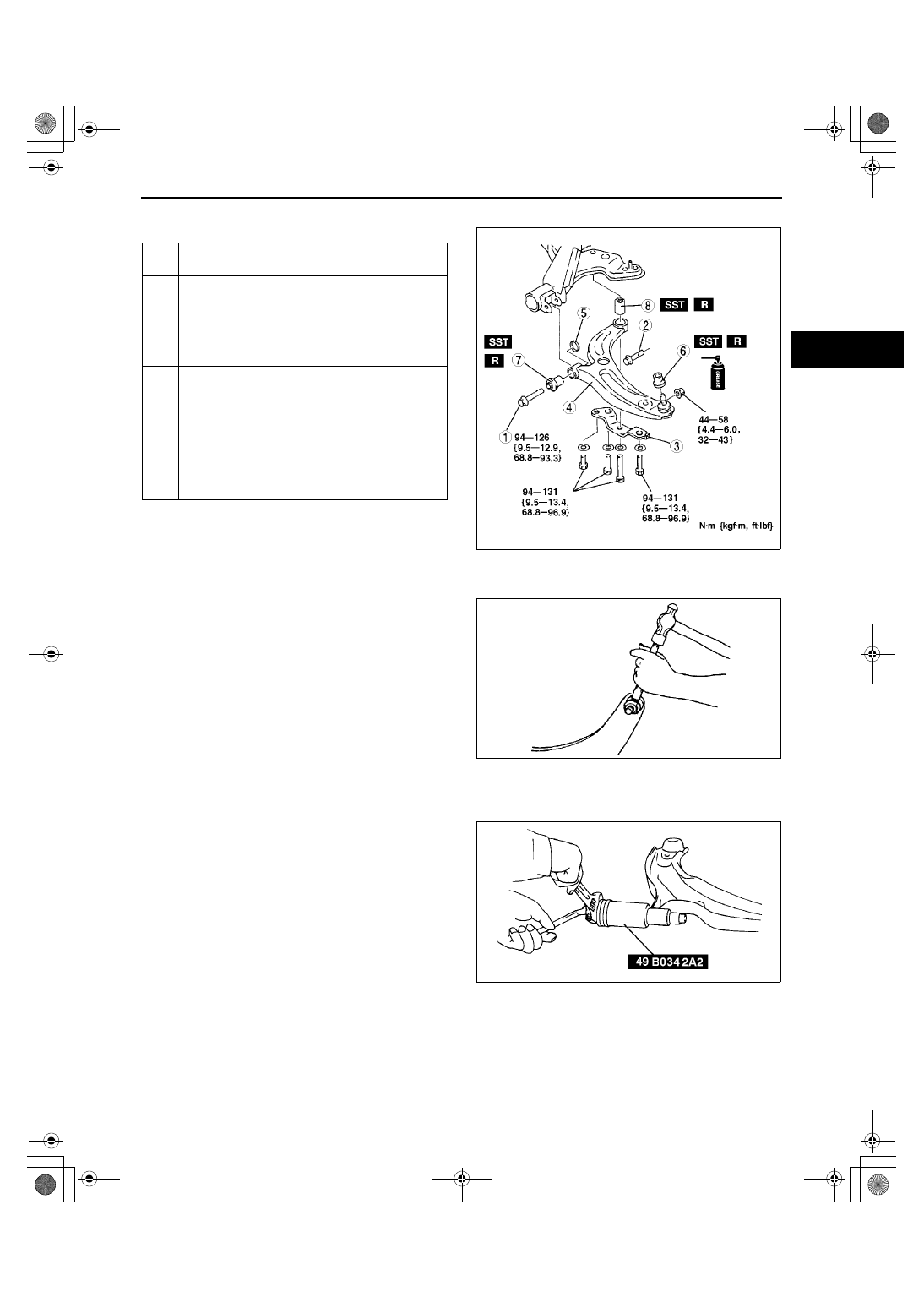
1. Remove in the order indicated in the table.
2. Install in the reverse order of removal.
Dust Boot Removal Note
1. Remove the dust boot using a chisel, being
careful not to damage the ball joint and the arm.
Lower Arm Bushing (Front) Removal Note
1. Cut away the projecting rubber of the lower arm bushing.
2. Set the SST onto the lower arm, and remove the
bushing.
1
Bolt
2
Bolt (Lower arm ball joint)
3
Bracket
4
Lower arm component
5
Stopper
6
Dust boot
(See 02–13–5 Dust Boot Removal Note)
(See 02–13–7 Dust Boot Installation Note)
7
Lower arm bushing (front)
(See 02–13–5 Lower Arm Bushing (Front) Removal
Note)
(See 02–13–6 Lower Arm Bushing (Front)
Installation Note)
8
Lower arm bushing (rear)
(See 02–13–6 Lower Arm Bushing (Rear) Removal
Note)
(See 02–13–6 Lower Arm Bushing (Rear)
Installation Note)
Z3U0213W008
Z3U0213W009
A3U0213W003
1712‑1U‑01G(02‑13).fm 5 ページ 2001年6月30日 土曜日 午前10時2分
FRONT SUSPENSION
02–13–6
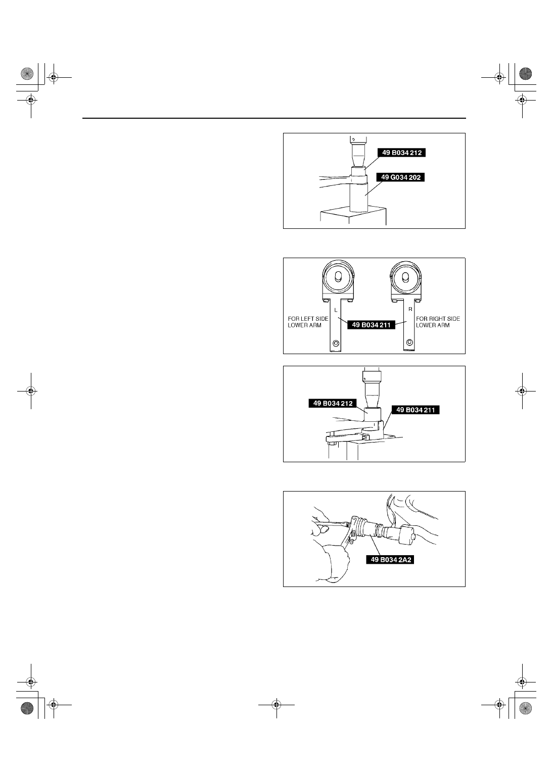
Lower Arm Bushing (Rear) Removal Note
1. Remove the lower arm bushing using the SSTs
and a press.
Lower Arm Bushing (Rear) Installation Note
1. Align the mark of the lower arm and the small
projection of the lower arm bushing (rear) as
shown in the figure.
2. Set the lower arm onto the SST (49 B034 211).
3. Press the new lower arm bushing using the SST
(49 B034 212).
Lower Arm Bushing (Front) Installation Note
1. Install the new bushing, and pull it into the lower
arm using the SST.
A3U0213W004
A3U0213W005
A3U0213W006
A3U0213W007
1712‑1U‑01G(02‑13).fm 6 ページ 2001年6月30日 土曜日 午前10時2分

FRONT SUSPENSION
02–13–7
02–13
Dust Boot Installation Note
1. Wipe the grease off the ball stud.
2. Fill the inside of the new dust boot with grease.
3. Press the boot onto the ball joint using the SST.
4. Wipe away the excess grease.
End Of Sie
FRONT LOWER ARM INSPECTION
A3U021334300W02
1. Remove the lower arm from the vehicle.
2. Inspect for damage, cracks, and bending.
3. Inspect the ball joint rotation torque.
(1) Rotate the ball joint 5 times.
(2) Connect the SST to the ball stud, and
measure the rotation torque using a pull
scale.
•
Replace it if not within the specification.
Ball joint preload
1.0—4.9 N·m {10—50 kgf·cm, 9—43 in·lbf}
Pull scale reading
14—44 N {1.4—4.5 kgf, 3—10 lbf}
End Of Sie
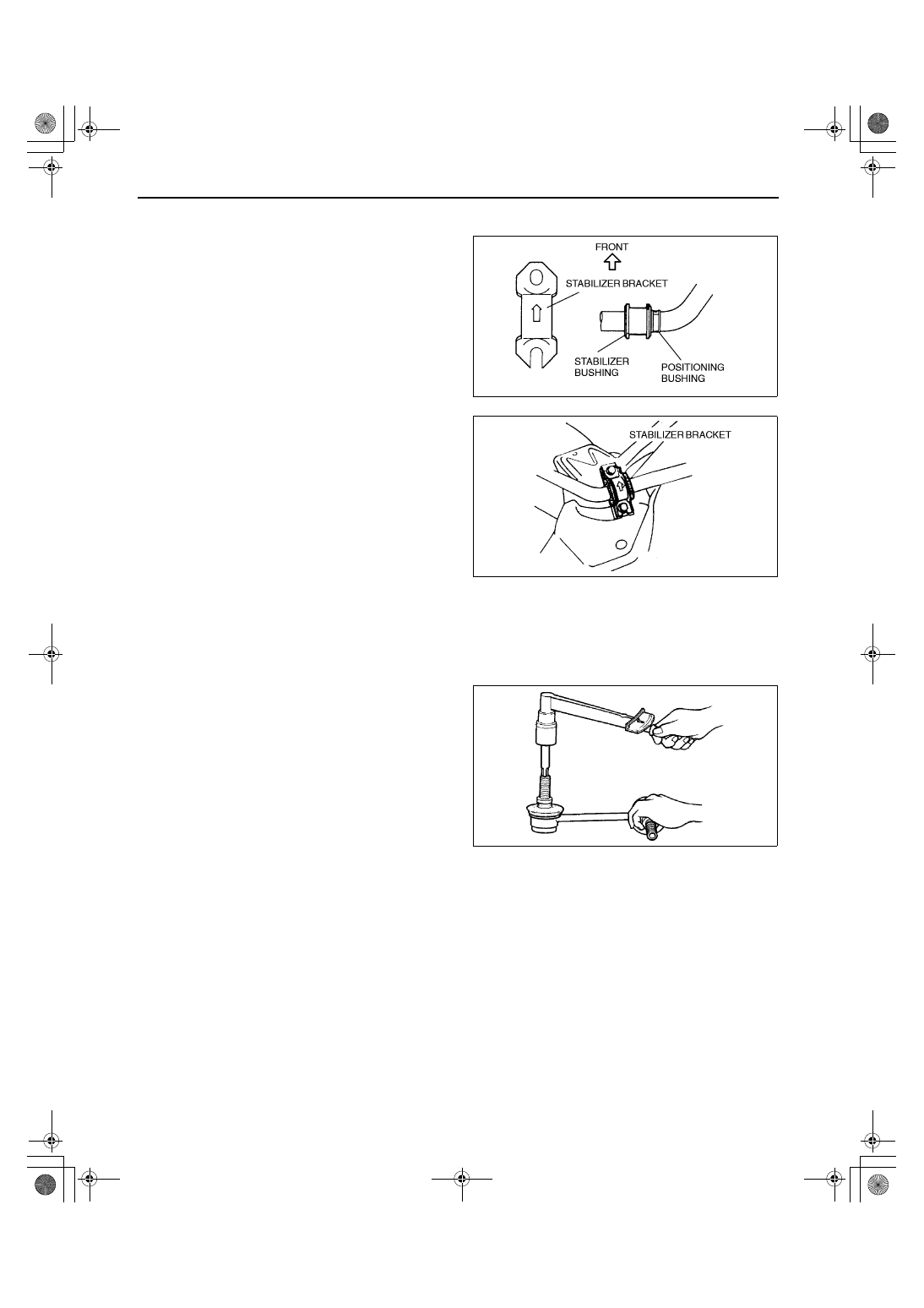
FRONT STABILIZER REMOVAL/INSTALLATION
A3U021334100W01
1. Remove the crossmember. (See 02–13–8 FRONT CROSSMEMBER REMOVAL/INSTALLATION.)
2. Remove in the order indicated in the table.
3. Install in the reverse order of removal.
4. Inspect the front wheel alignment and adjust it if
necessary.
Z3U0213W015
A3U0213W008
1
Stabilizer control link
2
Stabilizer bracket
(See 02–13–8 Stabilizer Bracket Installation Note)
3
Stabilizer bushing
4
Front stabilizer
Z3U0213W016
1712‑1U‑01G(02‑13).fm 7 ページ 2001年6月30日 土曜日 午前10時2分
FRONT SUSPENSION
02–13–8
Stabilizer Bracket Installation Note
1. Apply rubber grease to the inside surface of the stabilizer bushing.
2. Align the bushing with the inside of positioning
plate on the stabilizer bar.
3. Install the stabilizer bracket.
End Of Sie
STABILIZER CONTROL LINK (FRONT) INSPECTION
A3U021334150W01
1. Remove the stabilizer control link from the vehicle.
2. Inspect for bending and damage.
3. Measure the ball joint starting torque.
(1) Rock the ball joint stud side to side 10 times.
(2) Rotate the ball joint stud 10 times.
(3) Measure the starting torque using a suitable
Allen socket and a torque wrench.
Starting torque
0.2—2.5 N·m {1.4—26.0 kgf·cm, 1.3—22.0
in·lbf}
End Of Sie
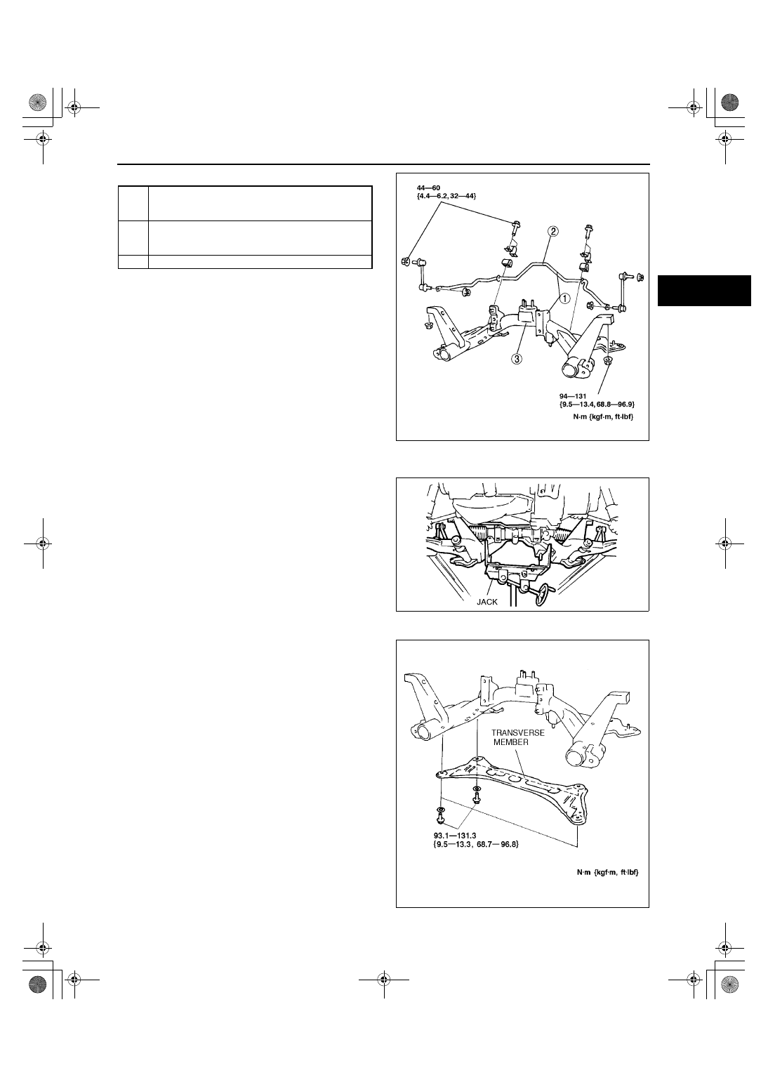
FRONT CROSSMEMBER REMOVAL/INSTALLATION
A3U021334800W01
1. For the MTX models, remove the change control rod and extension bar. (See 05–15A–4 MANUAL
TRANSAXLE (MTX) REMOVAL/INSTALLATION [F25M-R].)
2. Remove the front exhaust pipe. (See 01–15–1 EXHAUST SYSTEM REMOVAL/INSTALLATION.)
(See 01–15–1 EXHAUST SYSTEM REMOVAL/INSTALLATION.)
3. Remove the transverse member. (See02–13–9 TRANSVERSE MEMBER (ZM (ATX), FS) REMOVAL/
INSTALLATION)
4. Remove the steering gear and linkage. (See 06–12–9 STEERING GEAR AND LINKAGE REMOVAL/
INSTALLATION.)
5. Remove the front lower arm. (See 02–13–5 FRONT LOWER ARM REMOVAL/INSTALLATION.)
X3U213WAH
X3U213WAJ
X3U213WAK
1712‑1U‑01G(02‑13).fm 8 ページ 2001年6月30日 土曜日 午前10時2分
FRONT SUSPENSION
02–13–9
02–13
6. Remove in the order indicated in the table.
7. Install in the reverse order of removal.
8. Inspect the front wheel alignment as necessary.
Crossmember Component Removal Note
1. Support the crossmember using a jack and
remove the bolts and nuts.
2. Remove the crossmember component.
End Of Sie
TRANSVERSE MEMBER (ZM (ATX), FS) REMOVAL/INSTALLATION
A3U021334890W01
1. Remove the transverse member.
2. Install the transverse member.
End Of Sie
1
Crossmember component
(See 02–13–9 Crossmember Component Removal
Note)
2
Front stabilizer
(See 02–13–7 FRONT STABILIZER REMOVAL/
INSTALLATION)
3
Front crossmember
X3U213WAL
X3U213WAM
Y3E7414W001
1712‑1U‑01G(02‑13).fm 9 ページ 2001年6月30日 土曜日 午前10時2分
FRONT SUSPENSION
02–13–10
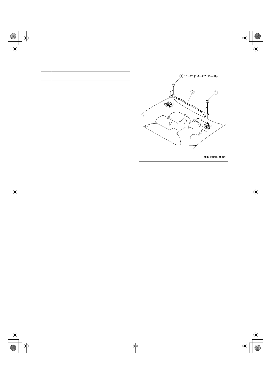
FRONT STRUT BAR REMOVAL/INSTALLATION
A3U021301015W02
1. Remove in the order indicated in the table.
2. Install in the reverse order of removal.
End Of Sie
1
Nut
2
Front strut bar
Y3A7414W002
1712‑1U‑01G(02‑13).fm 10 ページ 2001年6月30日 土曜日 午前10時2分
REAR SUSPENSION
02–14–1
02–14
02–14
REAR SUSPENSION
REAR SUSPENSION
LOCATION INDEX . . . . . . . . . . . . . . . . 02–14–1
REAR SHOCK ABSORBER AND
SPRING REMOVAL/INSTALLATION . . 02–14–2
Coil Spring Installation Note. . . . . . . . . 02–14–3
REAR SHOCK ABSORBER
INSPECTION . . . . . . . . . . . . . . . . . . . . . 02–14–3
REAR SHOCK ABSORBER
DISPOSAL. . . . . . . . . . . . . . . . . . . . . . . 02–14–3
REAR STABILIZER
REMOVAL/INSTALLATION . . . . . . . . . 02–14–4
Stabilizer Bushing and Bracket
Installation Note . . . . . . . . . . . . . . . . . 02–14–4
STABILIZER CONTROL LINK (REAR)
INSPECTION . . . . . . . . . . . . . . . . . . . . . 02–14–4
LATERAL LINK AND TRAILING LINK
REMOVAL/INSTALLATION . . . . . . . . . . 02–14–5
Nut, Cam Plate and Adjusting Cam
Bolt Removal Note . . . . . . . . . . . . . . . 02–14–5
Front Lateral Link Removal Note . . . . . 02–14–6
Nut, Cam Plate, and Adjusting Cam
Bolt Installation Note . . . . . . . . . . . . . . 02–14–6
End of Toc
REAR SUSPENSION LOCATION INDEX
A3U021401016W01
.
End Of Sie
Z3U0214W001
1
Rear shock absorber and coil spring
(See 02–14–2 REAR SHOCK ABSORBER AND
SPRING REMOVAL/INSTALLATION)
2
Rear shock absorber
(See 02–14–3 REAR SHOCK ABSORBER
INSPECTION)
(See 02–14–3 REAR SHOCK ABSORBER
DISPOSAL)
3
Rear stabilizer and stabilizer control link
(See 02–14–4 REAR STABILIZER REMOVAL/
INSTALLATION)
(See 02–14–4 STABILIZER CONTROL LINK
(REAR) INSPECTION)
4
Lateral link
(See 02–14–5 LATERAL LINK AND TRAILING
LINK REMOVAL/INSTALLATION)
5
Trailing link
(See 02–14–5 LATERAL LINK AND TRAILING
LINK REMOVAL/INSTALLATION)
6
Rear crossmember
(See 02–14–6 REAR CROSSMEMBER REMOVAL/
INSTALLATION)
1712‑1U‑01G(02‑14).fm 1 ページ 2001年6月29日 金曜日 午前9時55分
REAR SUSPENSION
02–14–2
REAR SHOCK ABSORBER AND SPRING REMOVAL/INSTALLATION
A3U021405910W01
Caution
••••
Performing the following procedures without first removing the ABS wheel-speed sensor may
possibly cause an open circuit in the harness if it is pulled by mistake. Before performing the
following procedures, remove the ABS wheel-speed sensor (axle side) and set it to an appropriate
place where the sensor will not be pulled by mistake while servicing the vehicle.
1. For the 4SD, remove the rear seat belt. (See 08–11–2 REAR SEAT BELT REMOVAL/INSTALLATION.) For
the 5HB, remove the trunk side trim. (See 09–17–15 TRUNK SIDE TRIM REMOVAL/INSTALLATION)
2. Remove in the order indicated in the table.
3. Install in the reverse order of removal.
.
X3U214WA0
1
Clip and brake hose
2
Stabilizer control link nut
3
Shock absorber bolt
4
Cap
5
Nut
6
Rear shock absorber and spring
7
Piston rod nut
(See 02–13–3 Piston Rod Nut Removal Note)
8
Washer
9
Mounting rubber
10
Upper spring seat
11
Coil spring
(See 02–14–3 Coil Spring Installation Note)
12
Stopper seat
13
Dust cover
14
Bound stopper
15
Lower spring seat rubber
16
Rear shock absorber
1712‑1U‑01G(02‑14).fm 2 ページ 2001年6月29日 金曜日 午前9時55分
REAR SUSPENSION
02–14–3
02–14
Coil Spring Installation Note
1. Temporarily install the coil spring, upper spring seat and mounting rubber on the shock absorber so that the
lower end of the coil spring is seated on the step of the lower spring seat.
2. Mark the coil spring, upper spring seat and
mounting rubber for proper installation as shown
in the figure. (The following figure shows how to
install the right side. Install the left side
symmetrically.)
3. Align the marks of the coil spring and upper
spring seat rubber. Protect the coil spring and
upper seat spring using a piece of cloth, then set
the SSTs.
4. Compress the coil spring using the SSTs.
5. Install the lower spring seat rubber on the lower
spring seat.
6. Install the shock absorber so that the lower end of
the coil spring is seated on the step of the lower
spring seat.
7. Align the marks of the mounting rubber and shock
absorber.
8. Install the washer and piston rod nut, then
remove the SSTs.
Piston rod nut tightening torque
55—67 N·m {5.6—6.9 kgf·m, 41—49 ft·lbf}
End Of Sie
REAR SHOCK ABSORBER INSPECTION
A3U021428700W01
1. Inspect the rear shock absorber using the same procedure as the front shock absorber. (See 02–13–4 FRONT
SHOCK ABSORBER INSPECTION.)
End Of Sie
REAR SHOCK ABSORBER DISPOSAL
A3U021428700W02
1. Dispose of the rear shock absorber using the same procedure as the front shock absorber. (See 02–13–4
FRONT SHOCK ABSORBER DISPOSAL.)
End Of Sie
X3U214WA1
A3U0214W001
1712‑1U‑01G(02‑14).fm 3 ページ 2001年6月29日 金曜日 午前9時55分
REAR SUSPENSION
02–14–4
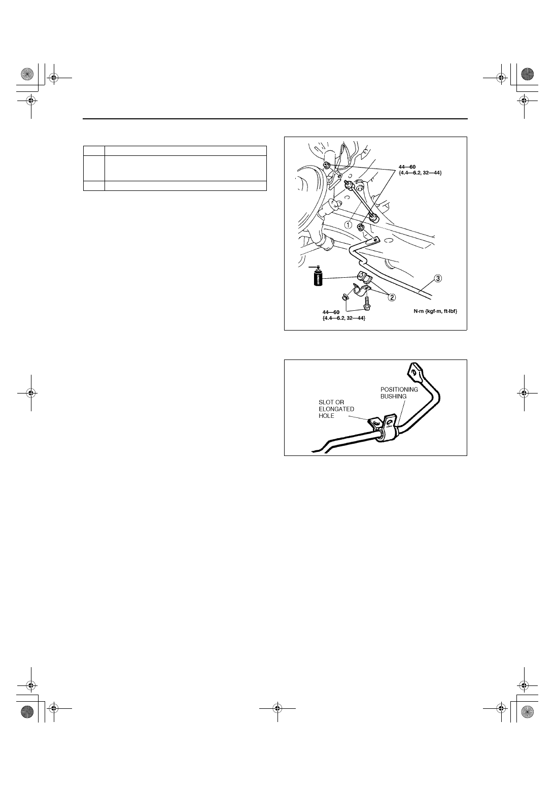
REAR STABILIZER REMOVAL/INSTALLATION
A3U021428100W01
1. Remove in the order indicated in the table.
2. Install in the reverse order of removal.
Stabilizer Bushing and Bracket Installation Note
1. Align the bushing with the positioning bushing on
the stabilizer bar.
2. Temporarily install the stabilizer bracket so that
the slot (or elongated hole) faces downward.
3. Tighten the stabilizer bracket nut, then bolt.
End Of Sie
STABILIZER CONTROL LINK (REAR) INSPECTION
A3U021434150W01
1. Inspect the rear stabilizer control link in the same procedure as the front stabilizer control link inspection.
(See 02–13–8 STABILIZER CONTROL LINK (FRONT) INSPECTION.)
End Of Sie
1
Stabilizer control link
2
Stabilizer bushing and bracket
(See 02–14–4 Stabilizer Bushing and Bracket
Installation Note)
3
Rear stabilizer
X3U214WA3
Z3U0214W101
1712‑1U‑01G(02‑14).fm 4 ページ 2001年6月29日 金曜日 午前9時55分
REAR SUSPENSION
02–14–5
02–14
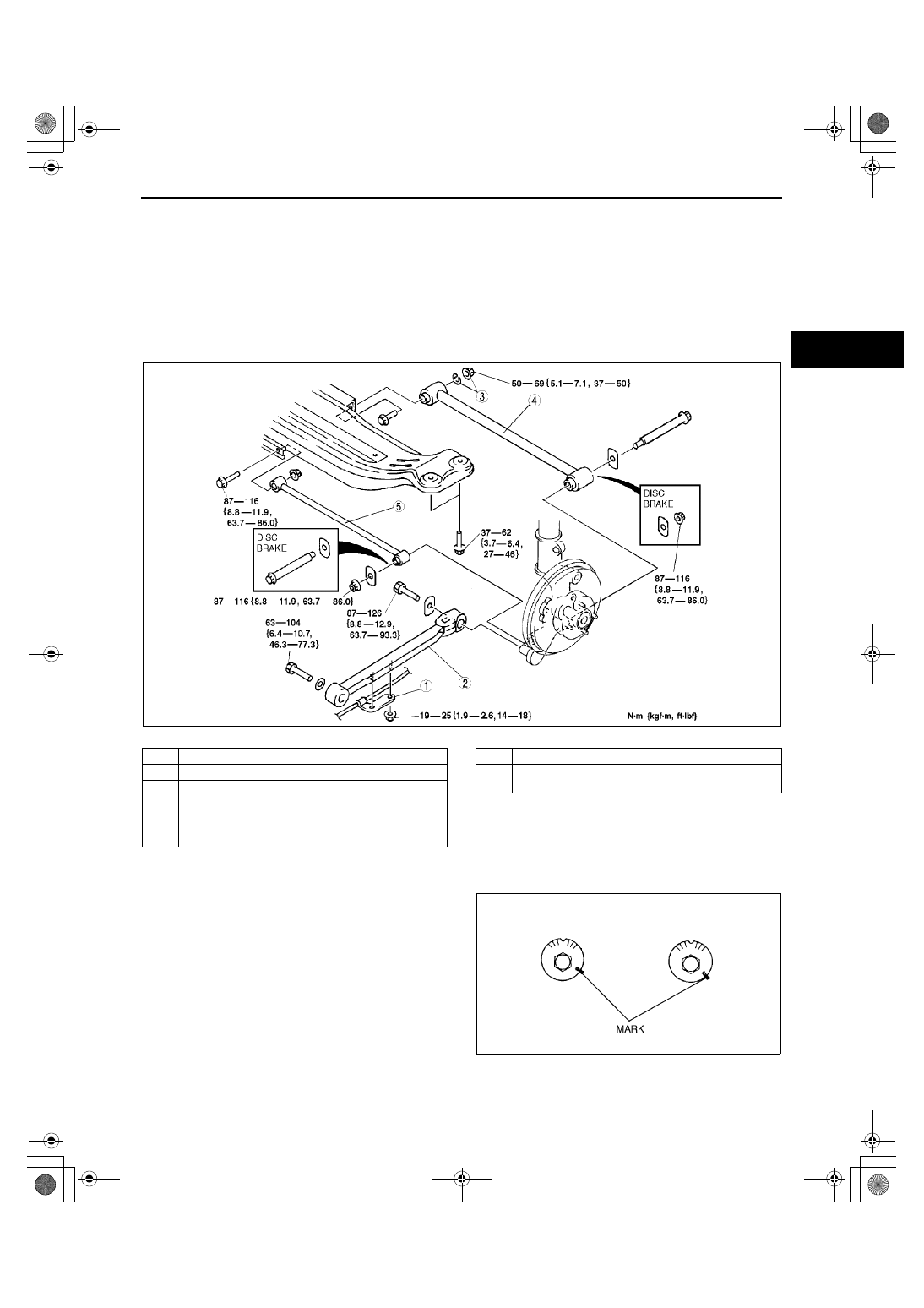
LATERAL LINK AND TRAILING LINK REMOVAL/INSTALLATION
A3U021428600W01
Caution
••••
Performing the following procedures without first removing the ABS wheel-speed sensor may
possibly cause an open circuit in the harness if it is pulled by mistake. Before performing the
following procedures, remove the ABS wheel-speed sensor (axle side) and fix it to an appropriate
place where the sensor will not be pulled by mistake while servicing the vehicle.
1. Remove in the order indicated in the table.
2. Install in the reverse order of removal.
3. Inspect the rear wheel alignment and adjust it as necessary.
.
Nut, Cam Plate and Adjusting Cam Bolt Removal Note
1. Before loosening the nut, make a mark on the
cam plate and the crossmember for reference
during installation.
Z3U0214W006
1
Parking brake cable bracket
2
Trailing link
3
Nut, cam plate and adjusting cam bolt
(See 02–14–5 Nut, Cam Plate and Adjusting Cam
Bolt Removal Note)
(See 02–14–6 Nut, Cam Plate, and Adjusting Cam
Bolt Installation Note)
4
Rear lateral link
5
Front lateral link
(See 02–14–6 Front Lateral Link Removal Note)
Y3U214WA1
1712‑1U‑01G(02‑14).fm 5 ページ 2001年6月29日 金曜日 午前9時55分
REAR SUSPENSION
02–14–6
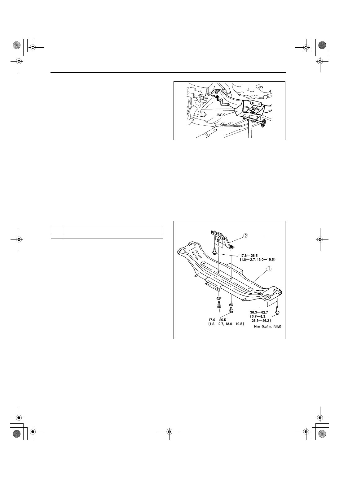
Front Lateral Link Removal Note
1. Support the rear crossmember using a jack, then
remove the crossmember bolts.
2. Lower the crossmember to remove the lateral link
bolt.
Nut, Cam Plate, and Adjusting Cam Bolt Installation Note
1. Install the cam plate so that the notch faces the same direction as the adjusting cam bolt.
2. Align with the mark made before removing the adjusting cam bolt.
3. Tighten the nut.
Tightening torque
50—69 N·m {5.1—7.1 kgf·m, 37—50 ft·lbf}
End Of Sie
REAR CROSSMEMBER REMOVAL/INSTALLATION
A3U021428400W01
1. Remove the rear stabilizer. (See 02–14–4 REAR STABILIZER REMOVAL/INSTALLATION.)
2. Remove the front and rear lateral links. (See 02–14–5 LATERAL LINK AND TRAILING LINK REMOVAL/
INSTALLATION.)
3. Remove in the order indicated in the table.
4. Install in the reverse order of removal.
5. Inspect the rear wheel alignment and adjust it as
necessary.
End Of Sie
X3U214WA7
1
Rear crossmember
2
Crossmember bracket
Z3U0214W100
1712‑1U‑01G(02‑14).fm 6 ページ 2001年6月29日 金曜日 午前9時55分
TECHNICAL DATA
02–50–1
02–50
02–50
TECHNICAL DATA
SUSPENSION TECHNICAL DATA. . . . . 02–50–1
End of Toc
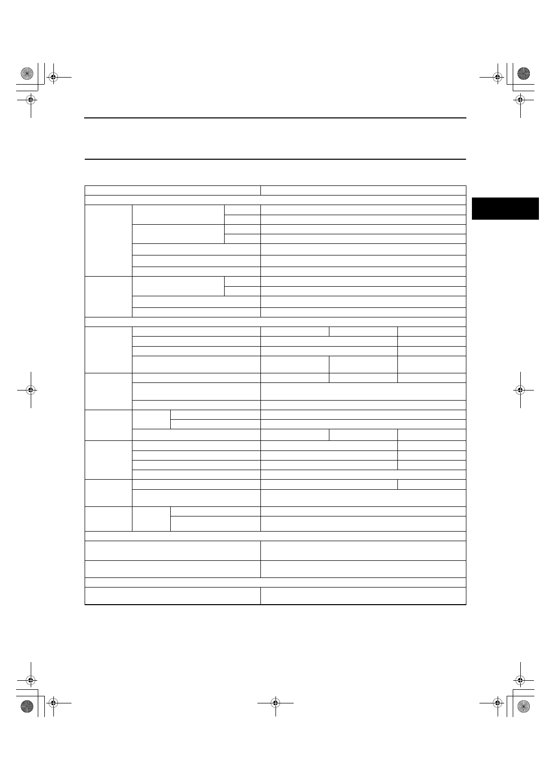
SUSPENSION TECHNICAL DATA
A3U025001013W01
*1 : Fuel tank is full. Engine coolant and engine oil are at specified levels. Spare tire, jack and tools are in
designated positions. Adjust to the median when carrying out wheel alignment.
*2 : Difference between left and right must not exceed 1
°°°°
30'.
*3 : 1 balance weight: max. 60 g {2.12 oz}. If the total weight exceeds 100 g {3.53 oz} on one side, rebalance after
moving the tire around on the rim. Do not use more than 2 balance weights on the inner or outer side of the
wheel.
End Of Sie
Item
Specification
WHEEL ALIGNMENT
Front wheel
alignment
(Unloaded)*
1
Maximum steering angle
Inner
37
°±
3
°
Outer
33
°±
3
°
Total toe-in
(mm {in})
2
±
4 {0.08
±
0.16}
(degree)
0
°
12
′±
24
′
Camber angle*
2
–0
°
49
′±
1
°
Caster angle*
2
1
°
56
′±
1
°
Kingpin angle (Reference value)
12
°
36
′
Rear wheel
alignment
(Unloaded)*
1
Total toe-in
(mm {in})
2
±
4 {0.08
±
0.16}
(degree)
0
°
12
′±
24
′
Camber angle*
2
(Reference value)
–0
°
31
′±
1
°
(14,15inch wheel), –0
°
34
′±
1
°
(16inch wheel)
Thrust angle (Reference value)
0
°±
48
′
WHEELS AND TIRES
Standard tire
wheel
Size
14
×
5 1/2JJ
15
×
6JJ
16
×
6JJ
Offset
(mm {in})
45 {1.77}
50 {1.97}
Pitch circle diameter
(mm {in})
100 {3.94}
114.3 {4.50}
Material
Steel
Steel or
aluminum alloy
Aluminum alloy
Standard tire
Size
P185/65R14 85S
P195/55R15 84V
P195/50R16 83V
Air
pressure
(kPa {kgf/cm
2
, psi})
220 {2.2, 32}
Remaining tread
(mm {in})
1.6 {0.063}
Standard tire
wheel and tire
Wheel and
tire runout
Radial direction
(mm {in})
1.5 {0.06 max.}
Lateral direction
(mm {in})
Steel: 2.5 {0.10} max., Aluminum: 2.0 {0.08} max.
Wheel unbalance*
3
(g {oz})
10 {0.35} max.
9 {0.32} max.
8 {0.30} max.
Temporary
spare tire
wheel
Size
14
×
4T
15
×
4T
Offset
(mm {in})
40 {1.58}
45 {1.77}
Pitch circle diameter
(mm {in})
100 {3.94}
114.3 {4.50}
Material
Steel
Temporary
spare tire
Size
T125/70 D14
T115/70 D15
Air
pressure
(kPa {kgf/cm
2
, psi})
420 {4.2, 60}
Temporary
spare tire
wheel and tire
Wheel and
tire runout
Radial direction
(mm {in})
2.0 {0.08} max.
Lateral direction
(mm {in})
2.5 {0.10} max.
FRONT SUSPENSION
Lower arm ball joint rotation torque (Pull scale reading)
14—44 {1.4—4.5, 3—10}
(N {kgf, lbf})
Stabilizer control link
rotation torque
(N·m {kgf·cm, in·lbf})
0.2—2.5 {1.4—26.0, 1.3—22.0}
REAR SUSPENSION
Stabilizer control link
rotation torque
(N·m {kgf·cm, in·lbf})
0.2—2.5 {1.4—26.0, 1.3—22.0}
1712‑1U‑01G(02‑50).fm 1 ページ 2001年6月29日 金曜日 午前9時56分
SERVICE TOOLS
02–60–1
02–60
02–60
SERVICE TOOLS
SUSPENSION SST . . . . . . . . . . . . . . . . . 02–60–1
End of Toc
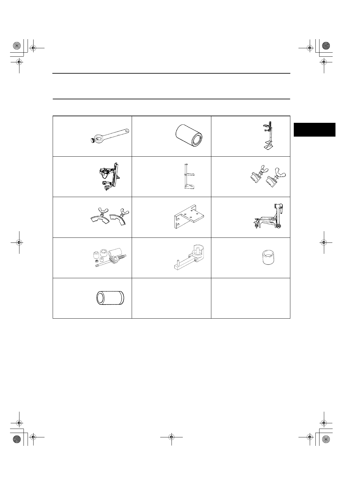
SUSPENSION SST
A3U026001013W01
End Of Sie
49 0180 510B
Preload
measuring
attachment
49 8038 785A
Dust boot
installer
49 T034 1A0
Coil spring
compressor set
49 T034 101
Spring
compressor
(Part of 49 T034
1A0)
49 T034 102
Stand (Part of
49 T034 1A0)
49 T034 103
Hook (Part of 49
T034 1A0)
49 T034 104
Support (Part of
49 T034 1A0)
49 T034 105
Attachment
49 0107 680A
Engine stand
49 B034 2A2
Rubber bushing
replacer set
49 B034 211
Rubber bushing
installer
49 B034 212
Rubber bushing
replacer
49 G034 202
Support block
—
—
1712‑1U‑01G(02‑60).fm 1 ページ 2001年6月29日 金曜日 午前9時56分
Document Outline
- Suspension
- General Procedures
- Wheel Alignment
- Front Suspension
- Front Suspension Location Index
- Front Shock Absorber and Coil Spring Removal/Installation
- Front Shock Absorber Inspection
- Front Shock Absorber Disposal
- Front Lower Arm Removal/Installation
- Front Lower Arm Inspection
- Front Crossmember Removal/Installation
- Transverse Member Removal/Installation
- Front Strut Bar Removal/Installation
- Rear Suspension
- Rear Suspension Location Index
- Rear Shock Absorber and Spring Removal/Installation
- Rear Shock Absorber Inspection
- Rear Shock Absorber Disposal
- Rear Stabilizer Removal/Installation
- Stabilizer Control Link (Rear) Inspection
- Lateral Link and Trailing Link Removal/Installation
- Rear Crossmember Removal/Installation
- Technical Data
- Service Tools
Wyszukiwarka
Podobne podstrony:
02 Polimeryzacja suspensyjna metakrylanu metylu
02 BMW Suspension Systems
02 E90 Suspension & Chassis
Wyk 02 Pneumatyczne elementy
02 OperowanieDanymiid 3913 ppt
02 Boża radość Ne MSZA ŚWIĘTAid 3583 ppt
OC 02
PD W1 Wprowadzenie do PD(2010 10 02) 1 1
02 Pojęcie i podziały prawaid 3482 ppt
WYKŁAD 02 SterowCyfrowe
02 filtracja
02 poniedziałek
21 02 2014 Wykład 1 Sala
Genetyka 2[1] 02
więcej podobnych podstron