FIRST PAGES
Chapter 5
5-1
MSS:
σ
1
− σ
3
= S
y
/n
⇒ n =
S
y
σ
1
− σ
3
DE:
n
=
S
y
σ
σ
=
σ
2
A
− σ
A
σ
B
+ σ
2
B
1
/
2
=
σ
2
x
− σ
x
σ
y
+ σ
2
y
+ 3τ
2
x y
1
/
2
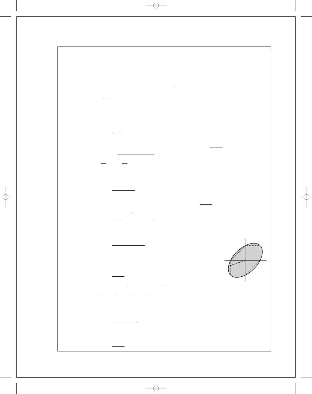
(a) MSS:
σ
1
= 12, σ
2
= 6, σ
3
= 0 kpsi
n
=
50
12
= 4.17 Ans.
DE:
σ
= (12
2
− 6(12) + 6
2
)
1
/
2
= 10.39 kpsi, n =
50
10
.39
= 4.81 Ans.
(b)
σ
A
,
σ
B
=
12
2
±
12
2
2
+ (−8)
2
= 16, −4 kpsi
σ
1
= 16, σ
2
= 0, σ
3
= −4 kpsi
MSS:
n
=
50
16
− (−4)
= 2.5 Ans.
DE:
σ
= (12
2
+ 3(−8
2
))
1
/
2
= 18.33 kpsi, n =
50
18
.33
= 2.73 Ans.
(c)
σ
A
,
σ
B
=
−6 − 10
2
±
−6 + 10
2
2
+ (−5)
2
= −2.615, −13.385 kpsi
σ
1
= 0, σ
2
= −2.615, σ
3
= −13.385 kpsi
MSS:
n
=
50
0
− (−13.385)
= 3.74 Ans.
DE:
σ
= [(−6)
2
− (−6)(−10) + (−10)
2
+ 3(−5)
2
]
1
/
2
= 12.29 kpsi
n
=
50
12
.29
= 4.07 Ans.
(d)
σ
A
,
σ
B
=
12
+ 4
2
±
12
− 4
2
2
+ 1
2
= 12.123, 3.877 kpsi
σ
1
= 12.123, σ
2
= 3.877, σ
3
= 0 kpsi
MSS:
n
=
50
12
.123 − 0
= 4.12 Ans.
DE:
σ
= [12
2
− 12(4) + 4
2
+ 3(1
2
)]
1
/
2
= 10.72 kpsi
n
=
50
10
.72
= 4.66 Ans.
B
A
budynas_SM_ch05.qxd 11/29/2006 15:00 Page 115
FIRST PAGES
116
Solutions Manual • Instructor’s Solution Manual to Accompany Mechanical Engineering Design
5-2 S
y
= 50 kpsi
MSS:
σ
1
− σ
3
= S
y
/n
⇒ n =
S
y
σ
1
− σ
3
DE:
σ
2
A
− σ
A
σ
B
+ σ
2
B
1
/
2
= S
y
/n
⇒ n = S
y
/
σ
2
A
− σ
A
σ
B
+ σ
2
B
1
/
2
(a) MSS:
σ
1
= 12 kpsi, σ
3
= 0, n =
50
12
− 0
= 4.17 Ans.
DE:
n
=
50
[12
2
− (12)(12) + 12
2
]
1
/
2
= 4.17 Ans.
(b) MSS:
σ
1
= 12 kpsi, σ
3
= 0, n =
50
12
= 4.17 Ans.
DE:
n
=
50
[12
2
− (12)(6) + 6
2
]
1
/
2
= 4.81 Ans.
(c) MSS:
σ
1
= 12 kpsi, σ
3
= −12 kpsi, n =
50
12
− (−12)
= 2.08 Ans.
DE:
n
=
50
[12
2
− (12)(−12) + (−12)
2
]
1
/
3
= 2.41 Ans.
(d) MSS:
σ
1
= 0, σ
3
= −12 kpsi, n =
50
−(−12)
= 4.17 Ans.
DE:
n
=
50
[(
−6)
2
− (−6)(−12) + (−12)
2
]
1
/
2
= 4.81
5-3 S
y
= 390 MPa
MSS:
σ
1
− σ
3
= S
y
/n
⇒ n =
S
y
σ
1
− σ
3
DE:
σ
2
A
− σ
A
σ
B
+ σ
2
B
1
/
2
= S
y
/n
⇒ n = S
y
/
σ
2
A
− σ
A
σ
B
+ σ
2
B
1
/
2
(a) MSS:
σ
1
= 180 MPa, σ
3
= 0, n =
390
180
= 2.17 Ans.
DE:
n
=
390
[180
2
− 180(100) + 100
2
]
1
/
2
= 2.50 Ans.
(b)
σ
A
,
σ
B
=
180
2
±
180
2
2
+ 100
2
= 224.5, −44.5 MPa = σ
1
,
σ
3
MSS:
n
=
390
224
.5 − (−44.5)
= 1.45 Ans.
DE:
n
=
390
[180
2
+ 3(100
2
)]
1
/
2
= 1.56 Ans.
budynas_SM_ch05.qxd 11/29/2006 15:00 Page 116
FIRST PAGES
Chapter 5
117
(c)
σ
A
,
σ
B
= −
160
2
±
−
160
2
2
+ 100
2
= 48.06, −208.06 MPa = σ
1
,
σ
3
MSS:
n
=
390
48
.06 − (−208.06)
= 1.52 Ans.
DE:
n
=
390
[
−160
2
+ 3(100
2
)]
1
/
2
= 1.65 Ans.
(d)
σ
A
,
σ
B
= 150, −150 MPa = σ
1
,
σ
3
MSS:
n
=
390
150
− (−150)
= 1.30 Ans.
DE:
n
=
390
[3(150)
2
]
1
/
2
= 1.50 Ans.
5-4 S
y
= 220 MPa
(a)
σ
1
= 100, σ
2
= 80, σ
3
= 0 MPa
MSS:
n
=
220
100
− 0
= 2.20 Ans.
DET:
σ
= [100
2
− 100(80) + 80
2
]
1
/
2
= 91.65 MPa
n
=
220
91
.65
= 2.40 Ans.
(b)
σ
1
= 100, σ
2
= 10, σ
3
= 0 MPa
MSS:
n
=
220
100
= 2.20 Ans.
DET:
σ
= [100
2
− 100(10) + 10
2
]
1
/
2
= 95.39 MPa
n
=
220
95
.39
= 2.31 Ans.
(c)
σ
1
= 100, σ
2
= 0, σ
3
= −80 MPa
MSS:
n
=
220
100
− (−80)
= 1.22 Ans.
DE:
σ
= [100
2
− 100(−80) + (−80)
2
]
1
/
2
= 156.2 MPa
n
=
220
156
.2
= 1.41 Ans.
(d)
σ
1
= 0, σ
2
= −80, σ
3
= −100 MPa
MSS:
n
=
220
0
− (−100)
= 2.20 Ans.
DE:
σ
= [(−80)
2
− (−80)(−100) + (−100)
2
]
= 91.65 MPa
n
=
220
91
.65
= 2.40 Ans.
budynas_SM_ch05.qxd 11/29/2006 15:00 Page 117
FIRST PAGES
118
Solutions Manual • Instructor’s Solution Manual to Accompany Mechanical Engineering Design
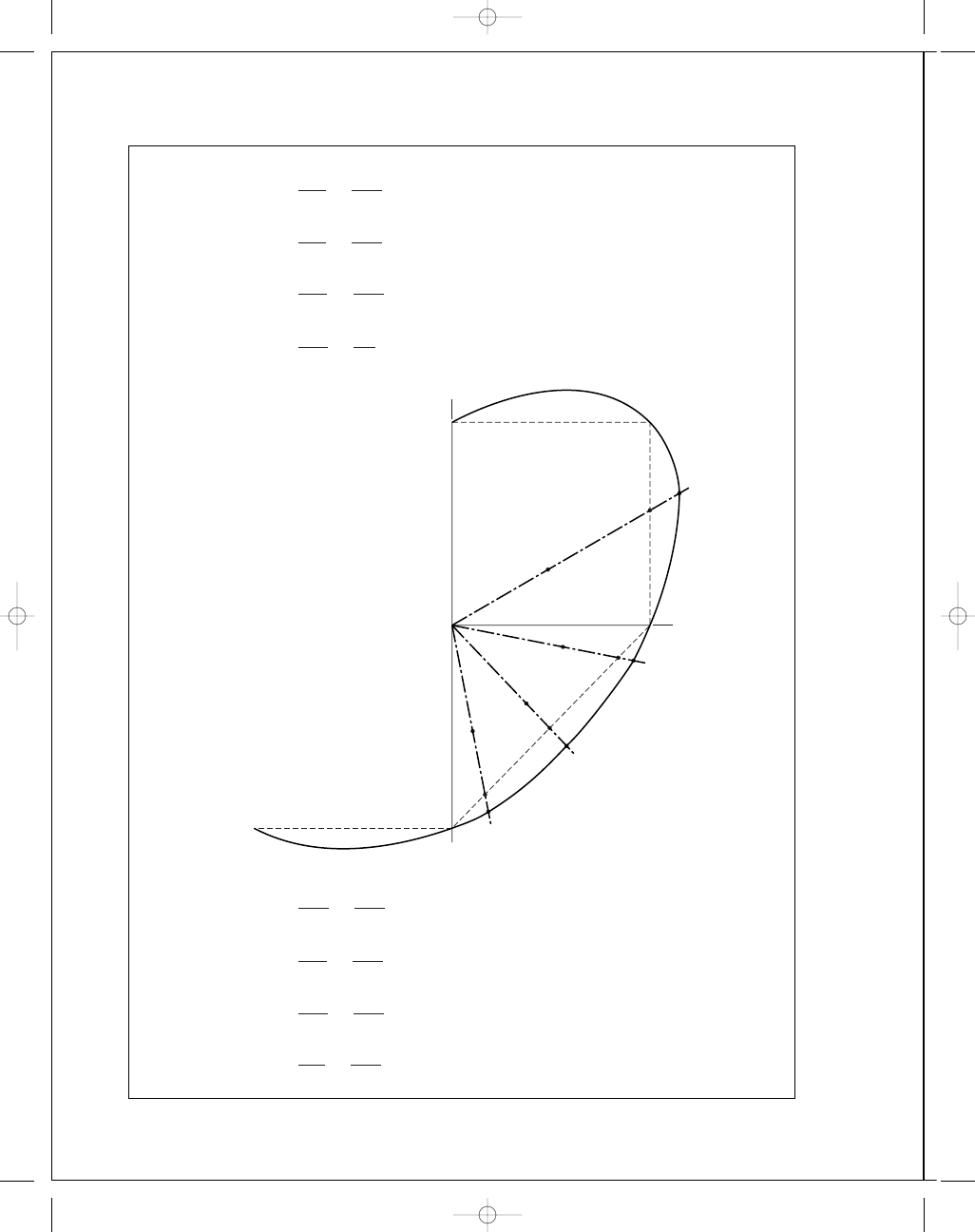
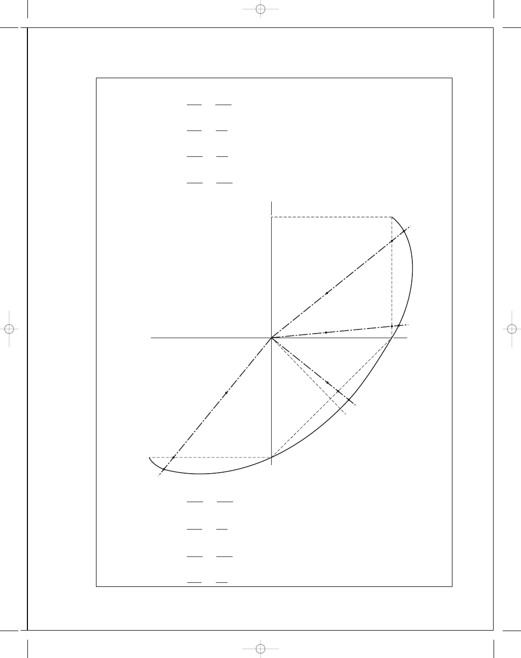
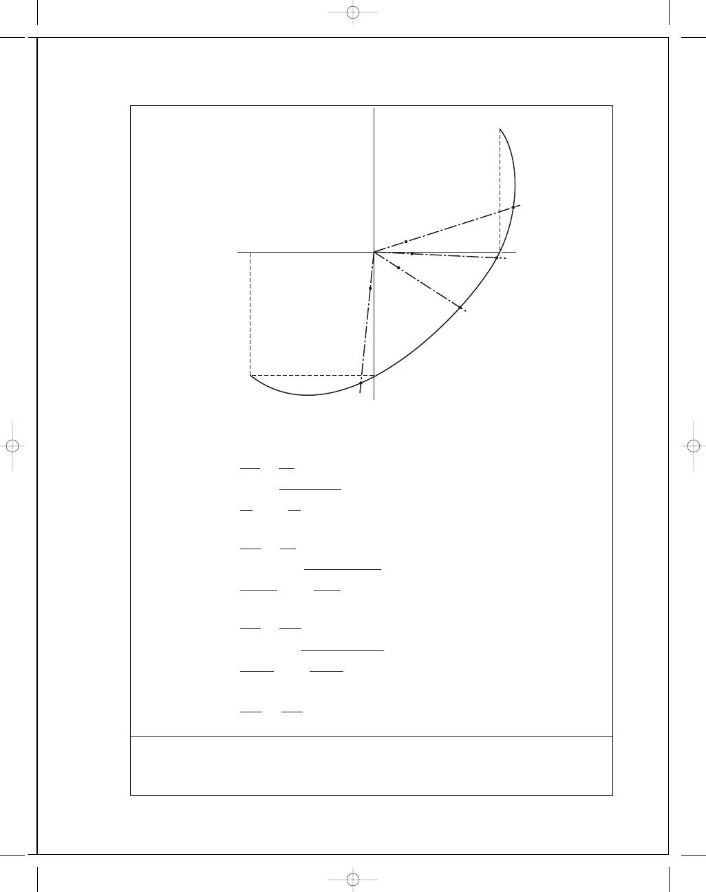
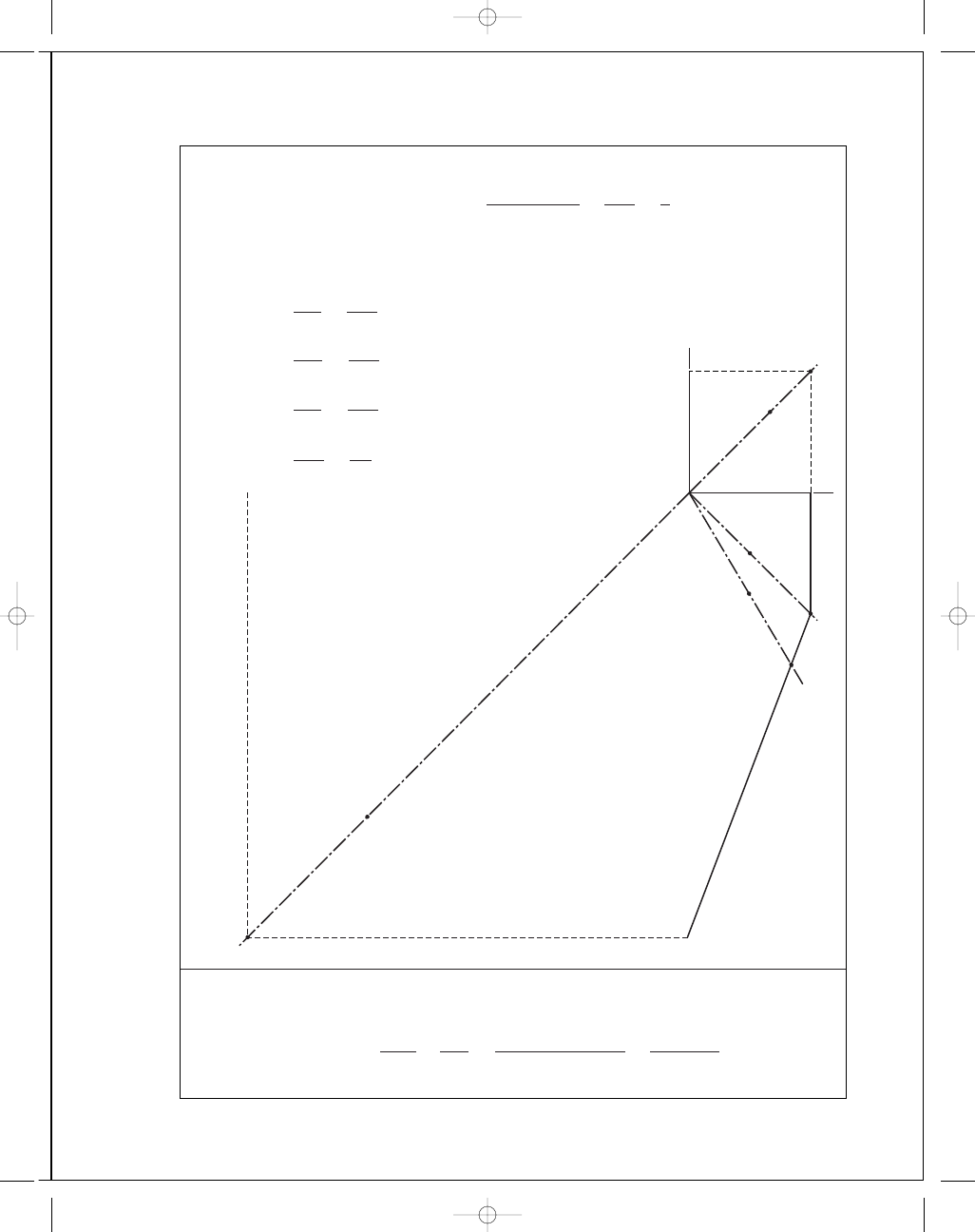
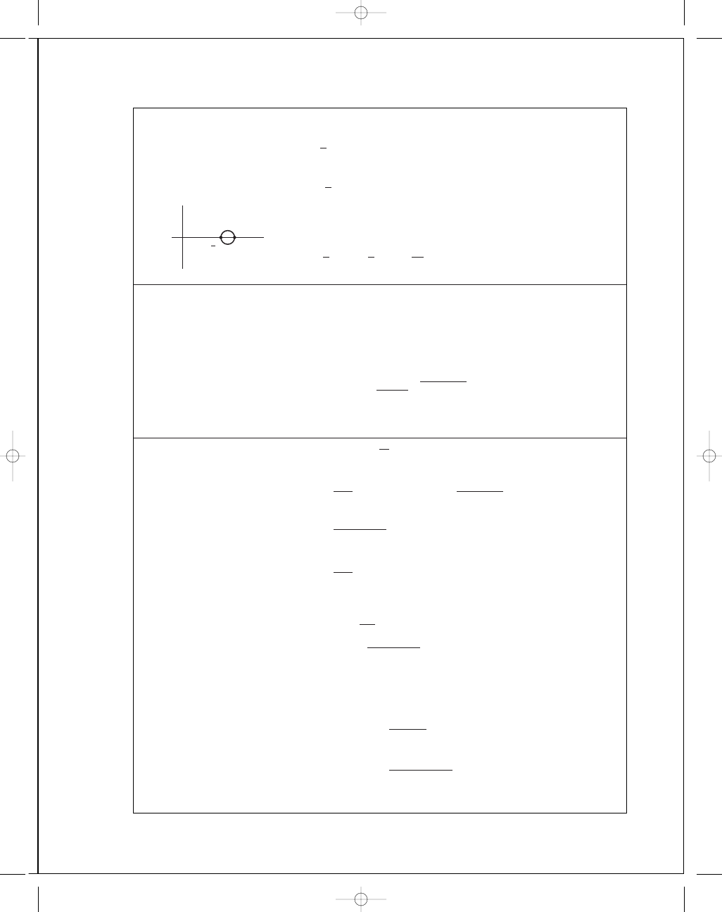
5-5
(a) MSS:
n
=
O B
O A
=
2
.23
1
.08
= 2.1
DE:
n
=
OC
O A
=
2
.56
1
.08
= 2.4
(b) MSS:
n
=
O E
O D
=
1
.65
1
.10
= 1.5
DE:
n
=
O F
O D
=
1
.8
1
.1
= 1.6
(c) MSS:
n
=
O H
O G
=
1
.68
1
.05
= 1.6
DE:
n
=
O I
O G
=
1
.85
1
.05
= 1.8
(d) MSS:
n
=
O K
O J
=
1
.38
1
.05
= 1.3
DE:
n
=
O L
O J
=
1
.62
1
.05
= 1.5
O
(a)
(b)
(d)
(c)
H
I
G
J
K
L
F
E
D
A
B
C
Scale
1"
⫽ 200 MPa
B
A
budynas_SM_ch05.qxd 11/29/2006 15:00 Page 118
FIRST PAGES
Chapter 5
119
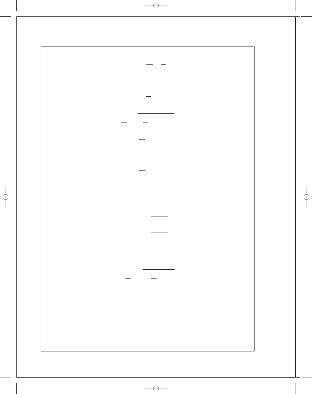
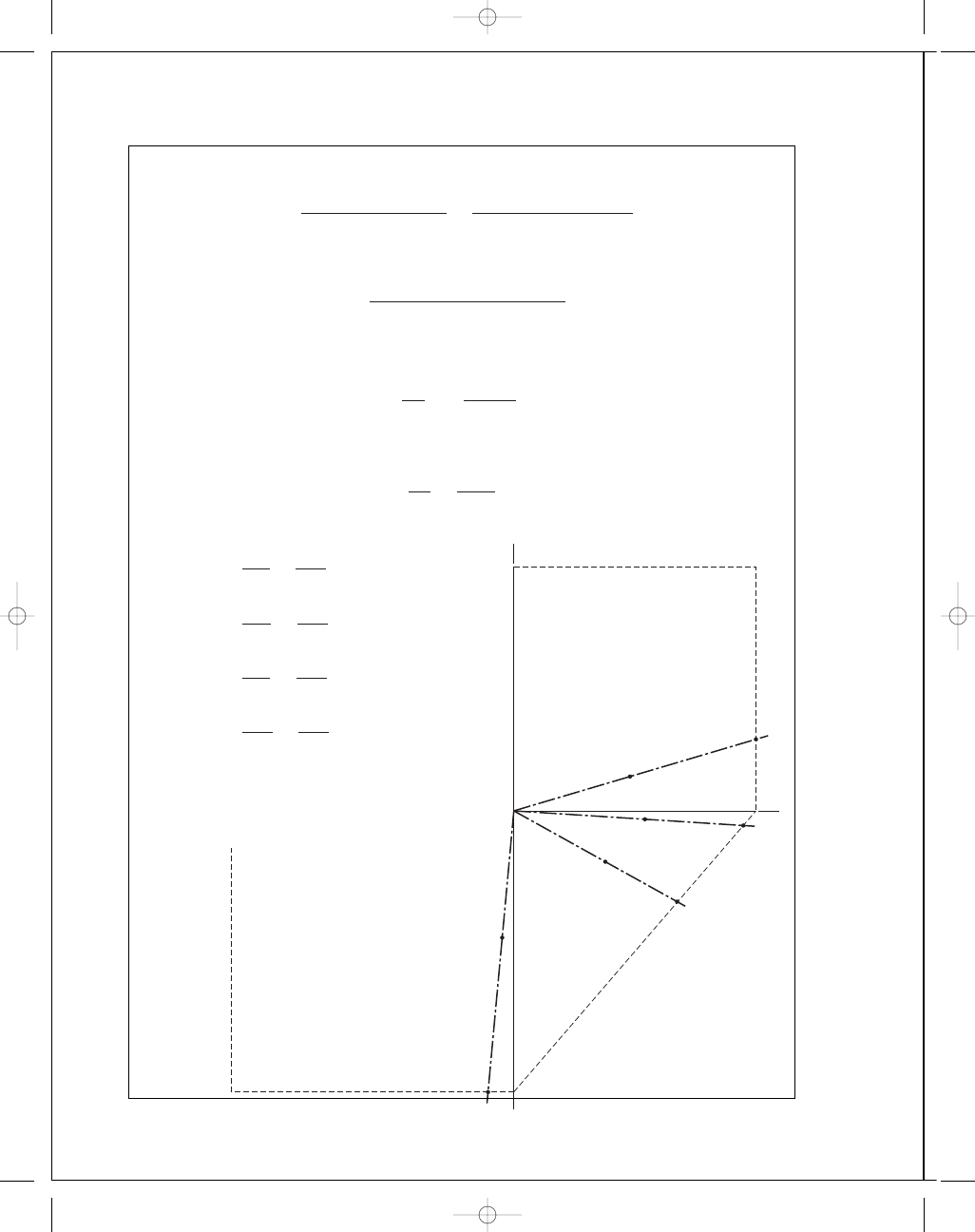
5-6 S
y
= 220 MPa
(a) MSS:
n
=
O B
O A
=
2
.82
1
.3
= 2.2
DE:
n
=
OC
O A
=
3
.1
1
.3
= 2.4
(b) MSS:
n
=
O E
O D
=
2
.2
1
= 2.2
DE:
n
=
O F
O D
=
2
.33
1
= 2.3
(c) MSS:
n
=
O H
O G
=
1
.55
1
.3
= 1.2
DE:
n
=
O I
O G
=
1
.8
1
.3
= 1.4
(d) MSS:
n
=
O K
O J
=
2
.82
1
.3
= 2.2
DE:
n
=
O L
O J
=
3
.1
1
.3
= 2.4
B
A
O
(a)
(b)
(c)
(d)
H
G
J
K
L
I
F
E
D
A
B
C
1"
⫽ 100 MPa
budynas_SM_ch05.qxd 11/29/2006 15:00 Page 119
FIRST PAGES
120
Solutions Manual • Instructor’s Solution Manual to Accompany Mechanical Engineering Design
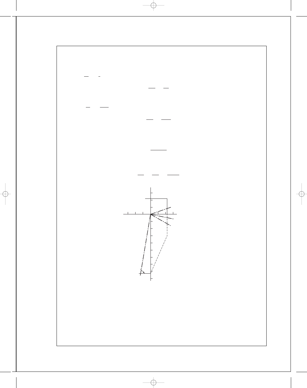
5-7 S
ut
= 30 kpsi, S
uc
= 100 kpsi; σ
A
= 20 kpsi, σ
B
= 6 kpsi
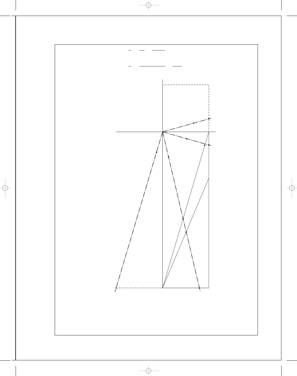
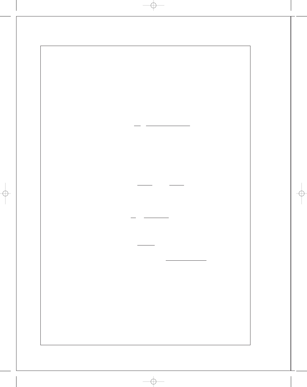
(a) MNS: Eq. (5-30a)
n
=
S
ut
σ
x
=
30
20
= 1.5 Ans.
BCM: Eq
. (5-31a)
n
=
30
20
= 1.5 Ans.
MM: Eq
. (5-32a)
n
=
30
20
= 1.5 Ans.
(b)
σ
x
= 12 kpsi,τ
x y
= −8 kpsi
σ
A
,
σ
B
=
12
2
±
12
2
2
+ (−8)
2
= 16, −4 kpsi
MNS: Eq. (5-30a)
n
=
30
16
= 1.88 Ans.
BCM: Eq. (5-31b)
1
n
=
16
30
−
(
−4)
100
⇒ n = 1.74 Ans.
MM: Eq. (5-32a)
n
=
30
16
= 1.88 Ans.
(c)
σ
x
= −6 kpsi, σ
y
= −10 kpsi,τ
x y
= −5 kpsi
σ
A
,
σ
B
=
−6 − 10
2
±
−6 + 10
2
2
+ (−5)
2
= −2.61, −13.39 kpsi
MNS: Eq. (5-30b)
n
= −
100
−13.39
= 7.47 Ans.
BCM: Eq. (5-31c)
n
= −
100
−13.39
= 7.47 Ans.
MM: Eq. (5-32c)
n
= −
100
−13.39
= 7.47 Ans.
(d)
σ
x
= −12 kpsi,τ
x y
= 8 kpsi
σ
A
,
σ
B
= −
12
2
±
−
12
2
2
+ 8
2
= 4, −16 kpsi
MNS: Eq. (5-30b)
n
=
−100
−16
= 6.25 Ans.
budynas_SM_ch05.qxd 11/29/2006 15:00 Page 120
FIRST PAGES
Chapter 5
121
BCM: Eq. (5-31b)
1
n
=
4
30
−
(
−16)
100
⇒ n = 3.41 Ans.
MM: Eq. (5-32b)
1
n
=
(100
− 30)4
100(30)
−
−16
100
⇒ n = 3.95 Ans.
(c)
L
(d)
J
(b)
(a)
H
G
K
F
O
C
D
E
A
B
1"
⫽ 20 kpsi
B
A
budynas_SM_ch05.qxd 11/29/2006 15:00 Page 121
FIRST PAGES
122
Solutions Manual • Instructor’s Solution Manual to Accompany Mechanical Engineering Design
5-8 See Prob. 5-7 for plot.
(a) For all methods:
n
=
O B
O A
=
1
.55
1
.03
= 1.5
(b) BCM:
n
=
O D
OC
=
1
.4
0
.8
= 1.75
All other methods:
n
=
O E
OC
=
1
.55
0
.8
= 1.9
(c) For all methods:
n
=
O L
O K
=
5
.2
0
.68
= 7.6
(d) MNS:
n
=
O J
O F
=
5
.12
0
.82
= 6.2
BCM:
n
=
O G
O F
=
2
.85
0
.82
= 3.5
MM:
n
=
O H
O F
=
3
.3
0
.82
= 4.0
5-9 Given: S
y
= 42 kpsi, S
ut
= 66.2 kpsi, ε
f
= 0.90. Since ε
f
> 0.05, the material is ductile and
thus we may follow convention by setting S
yc
= S
yt
.
Use DE theory for analytical solution. For
σ
, use Eq. (5-13) or (5-15) for plane stress and
Eq. (5-12) or (5-14) for general 3-D.
(a)
σ
= [9
2
− 9(−5) + (−5)
2
]
1
/
2
= 12.29 kpsi
n
=
42
12
.29
= 3.42 Ans.
(b)
σ
= [12
2
+ 3(3
2
)]
1
/
2
= 13.08 kpsi
n
=
42
13
.08
= 3.21 Ans.
(c)
σ
= [(−4)
2
− (−4)(−9) + (−9)
2
+ 3(5
2
)]
1
/
2
= 11.66 kpsi
n
=
42
11
.66
= 3.60 Ans.
(d)
σ
= [11
2
− (11)(4) + 4
2
+ 3(1
2
)]
1
/
2
= 9.798
n
=
42
9
.798
= 4.29 Ans.
budynas_SM_ch05.qxd 11/29/2006 15:00 Page 122
FIRST PAGES
Chapter 5
123
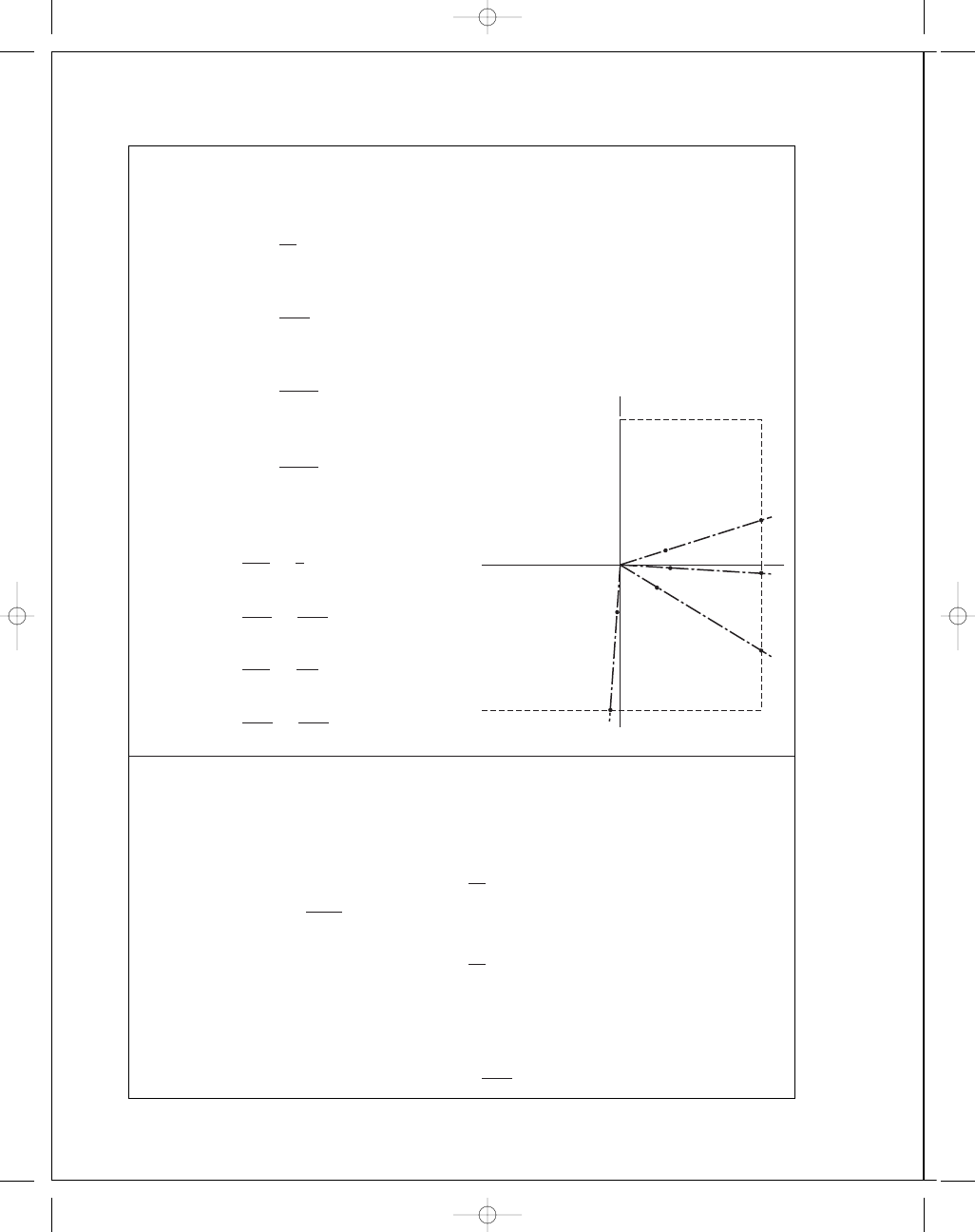
For graphical solution, plot load lines on DE envelope as shown.
(a)
σ
A
= 9, σ
B
= −5 kpsi
n
=
O B
O A
=
3
.5
1
= 3.5 Ans.
(b)
σ
A
,
σ
B
=
12
2
±
12
2
2
+ 3
2
= 12.7, −0.708 kpsi
n
=
O D
OC
=
4
.2
1
.3
= 3.23
(c)
σ
A
,
σ
B
=
−4 − 9
2
±
4
− 9
2
2
+ 5
2
= −0.910, −12.09 kpsi
n
=
O F
O E
=
4
.5
1
.25
= 3.6 Ans.
(d)
σ
A
,
σ
B
=
11
+ 4
2
±
11
− 4
2
2
+ 1
2
= 11.14, 3.86 kpsi
n
=
O H
O G
=
5
.0
1
.15
= 4.35 Ans.
5-10
This heat-treated steel exhibits S
yt
= 235 kpsi, S
yc
= 275 kpsi and ε
f
= 0.06. The steel is
ductile (
ε
f
> 0.05) but of unequal yield strengths. The Ductile Coulomb-Mohr hypothesis
(DCM) of Fig. 5-19 applies — confine its use to first and fourth quadrants.
(c)
(a)
(b)
(d)
E
C
G
H
D
B
A
O
F
1 cm
⫽ 10 kpsi
B
A
budynas_SM_ch05.qxd 11/29/2006 15:00 Page 123
FIRST PAGES
124
Solutions Manual • Instructor’s Solution Manual to Accompany Mechanical Engineering Design
(a)
σ
x
= 90 kpsi, σ
y
= −50 kpsi, σ
z
= 0 σ
A
= 90 kpsi and σ
B
= −50 kpsi. For the
fourth quadrant, from Eq. (5-31b)
n
=
1
(
σ
A
/S
yt
)
− (σ
B
/S
uc
)
=
1
(90
/235) − (−50/275)
= 1.77 Ans.
(b)
σ
x
= 120 kpsi, τ
x y
= −30 kpsi ccw. σ
A
,
σ
B
= 127.1, −7.08 kpsi. For the fourth
quadrant
n
=
1
(127
.1/235) − (−7.08/275)
= 1.76 Ans.
(c)
σ
x
= −40 kpsi, σ
y
= −90 kpsi, τ
x y
= 50 kpsi. σ
A
,
σ
B
= −9.10, −120.9 kpsi.
Although no solution exists for the third quadrant, use
n
= −
S
yc
σ
y
= −
275
−120.9
= 2.27 Ans.
(d)
σ
x
= 110 kpsi, σ
y
= 40 kpsi, τ
x y
= 10 kpsi cw. σ
A
,
σ
B
= 111.4, 38.6 kpsi. For the
first quadrant
n
=
S
yt
σ
A
=
235
111
.4
= 2.11 Ans.
Graphical Solution:
(a) n
=
O B
O A
=
1
.82
1
.02
= 1.78
(b) n
=
O D
OC
=
2
.24
1
.28
= 1.75
(c) n
=
O F
O E
=
2
.75
1
.24
= 2.22
(d) n
=
O H
O G
=
2
.46
1
.18
= 2.08
O
(d)
(b)
(a)
(c)
E
F
B
D
G
C
A
H
1 in
⫽ 100 kpsi
B
A
budynas_SM_ch05.qxd 11/29/2006 15:00 Page 124
FIRST PAGES
Chapter 5
125
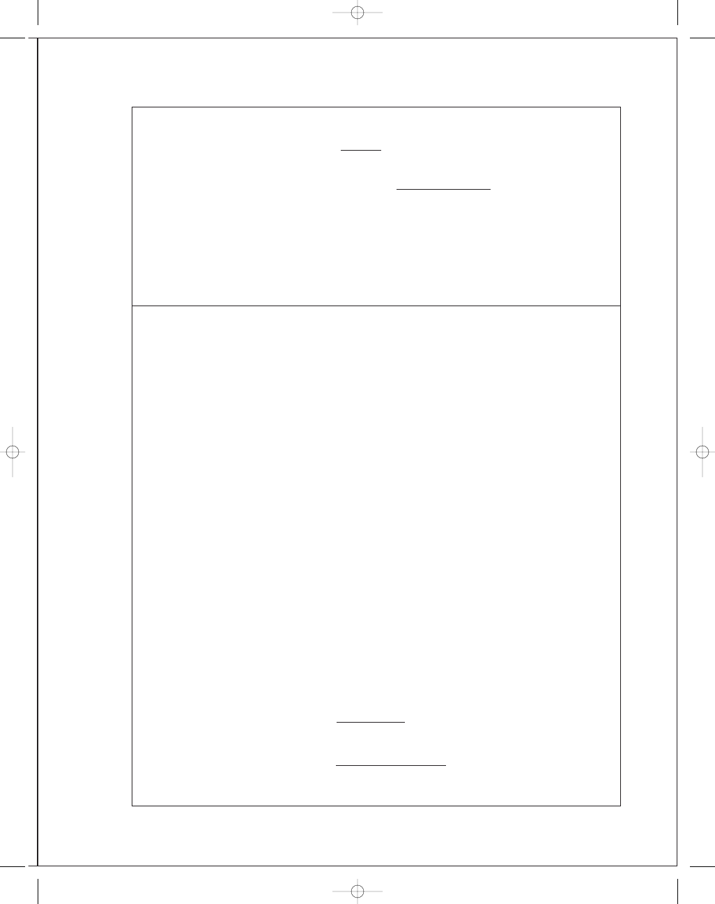
5-11
The material is brittle and exhibits unequal tensile and compressive strengths. Decision:
Use the Modified Mohr theory.
S
ut
= 22 kpsi, S
uc
= 83 kpsi
(a)
σ
x
= 9 kpsi, σ
y
= −5 kpsi. σ
A
,
σ
B
= 9, −5 kpsi. For the fourth quadrant,
|
σ
B
σ
A
| =
5
9
< 1, use Eq. (5-32a)
n
=
S
ut
σ
A
=
22
9
= 2.44 Ans.
(b)
σ
x
= 12 kpsi, τ
x y
= −3 kpsi ccw. σ
A
,
σ
B
= 12.7, −0.708 kpsi. For the fourth quad-
rant,
|
σ
B
σ
A
| =
0
.
708
12
.
7
< 1,
n
=
S
ut
σ
A
=
22
12
.7
= 1.73 Ans.
(c)
σ
x
= −4 kpsi, σ
y
= −9 kpsi, τ
x y
= 5 kpsi. σ
A
,
σ
B
= −0.910, −12.09 kpsi. For the
third quadrant, no solution exists; however, use Eq. (6-32c)
n
=
−83
−12.09
= 6.87 Ans.
(d)
σ
x
= 11 kpsi, σ
y
= 4 kpsi,τ
x y
= 1 kpsi. σ
A
,
σ
B
= 11.14, 3.86 kpsi. Forthefirstquadrant
n
=
S
A
σ
A
=
S
yt
σ
A
=
22
11
.14
= 1.97 Ans.
30
30
S
ut
⫽ 22
S
ut
⫽ 83
B
A
–50
–90
(d )
(b)
(a)
(c)
budynas_SM_ch05.qxd 11/29/2006 15:00 Page 125
FIRST PAGES
126
Solutions Manual • Instructor’s Solution Manual to Accompany Mechanical Engineering Design
5-12
Since
ε
f
< 0.05, the material is brittle. Thus, S
ut
.= S
uc
and we may use MM which is
basically the same as MNS.
(a)
σ
A
,
σ
B
= 9, −5 kpsi
n
=
35
9
= 3.89 Ans.
(b)
σ
A
,
σ
B
= 12.7, −0.708 kpsi
n
=
35
12
.7
= 2.76 Ans.
(c)
σ
A
,
σ
B
= −0.910, −12.09 kpsi (3rd quadrant)
n
=
36
12
.09
= 2.98 Ans.
(d)
σ
A
,
σ
B
= 11.14, 3.86 kpsi
n
=
35
11
.14
= 3.14 Ans.
Graphical Solution:
(a) n
=
O B
O A
=
4
1
= 4.0 Ans.
(b) n
=
O D
OC
=
3
.45
1
.28
= 2.70 Ans.
(c) n
=
O F
O E
=
3
.7
1
.3
= 2.85 Ans. (3rd quadrant)
(d) n
=
O H
O G
=
3
.6
1
.15
= 3.13 Ans.
5-13
S
ut
= 30 kpsi, S
uc
= 109 kpsi
Use MM:
(a)
σ
A
,
σ
B
= 20, 20 kpsi
Eq. (5-32a):
n
=
30
20
= 1.5 Ans.
(b)
σ
A
,
σ
B
= ±
(15)
2
= 15, −15 kpsi
Eq. (5-32a)
n
=
30
15
= 2 Ans.
(c)
σ
A
,
σ
B
= −80, −80 kpsi
For the 3rd quadrant, there is no solution but use Eq. (5-32c).
Eq. (5-32c):
n
= −
109
−80
= 1.36 Ans.
O
G
C
D
A
B
E
F
H
(a)
(c)
(b)
(d)
1 cm
⫽ 10 kpsi
B
A
budynas_SM_ch05.qxd 11/29/2006 15:00 Page 126
FIRST PAGES
Chapter 5
127
(d)
σ
A
,
σ
B
= 15, −25 kpsi, |σ
B
|σ
A
| = 25/15 > 1,
Eq. (5-32b):
(109
− 30)15
109(30)
−
−25
109
=
1
n
n
= 1.69 Ans.
(a) n
=
O B
O A
=
4
.25
2
.83
= 1.50
(b) n
=
O D
OC
=
4
.24
2
.12
= 2.00
(c) n
=
O F
O E
=
15
.5
11
.3
= 1.37 (3rd quadrant)
(d) n
=
O H
O G
=
4
.9
2
.9
= 1.69
5-14
Given: AISI 1006 CD steel, F
= 0.55 N, P = 8.0 kN, and T = 30 N · m, applying the
DE theory to stress elements A and B with S
y
= 280 MPa
A:
σ
x
=
32Fl
πd
3
+
4P
πd
2
=
32(0
.55)(10
3
)(0
.1)
π(0.020
3
)
+
4(8)(10
3
)
π(0.020
2
)
= 95.49(10
6
) Pa
= 95.49 MPa
O
(d)
(b)
(a)
(c)
E
F
C
B
A
G
D
H
1 cm
⫽ 10 kpsi
B
A
budynas_SM_ch05.qxd 11/29/2006 15:00 Page 127
FIRST PAGES
128
Solutions Manual • Instructor’s Solution Manual to Accompany Mechanical Engineering Design
τ
x y
=
16T
πd
3
=
16(30)
π(0.020
3
)
= 19.10(10
6
) Pa
= 19.10 MPa
σ
=
σ
2
x
+ 3τ
2
x y
1
/
2
= [95.49
2
+ 3(19.1)
2
]
1
/
2
= 101.1 MPa
n
=
S
y
σ
=
280
101
.1
= 2.77 Ans.
B:
σ
x
=
4P
πd
3
=
4(8)(10
3
)
π(0.020
2
)
= 25.47(10
6
) Pa
= 25.47 MPa
τ
x y
=
16T
πd
3
+
4
3
V
A
=
16(30)
π(0.020
3
)
+
4
3
0
.55(10
3
)
(
π/4)(0.020
2
)
= 21.43(10
6
) Pa
= 21.43 MPa
σ
= [25.47
2
+ 3(21.43
2
)]
1
/
2
= 45.02 MPa
n
=
280
45
.02
= 6.22 Ans.
5-15
S
y
= 32 kpsi
At A, M
= 6(190) = 1 140 lbf·in, T = 4(190) = 760 lbf · in.
σ
x
=
32M
πd
3
=
32(1140)
π(3/4)
3
= 27 520 psi
τ
zx
=
16T
πd
3
=
16(760)
π(3/4)
3
= 9175 psi
τ
max
=
27 520
2
2
+ 9175
2
= 16 540 psi
n
=
S
y
2
τ
max
=
32
2(16
.54)
= 0.967 Ans.
MSS predicts yielding
5-16
From Prob. 4-15,
σ
x
= 27.52 kpsi, τ
zx
= 9.175 kpsi. For Eq. (5-15), adjusted for coordinates,
σ
=
27
.52
2
+ 3(9.175)
2
1
/
2
= 31.78 kpsi
n
=
S
y
σ
=
32
31
.78
= 1.01 Ans.
DE predicts no yielding, but it is extremely close. Shaft size should be increased.
budynas_SM_ch05.qxd 11/29/2006 15:00 Page 128
FIRST PAGES
Chapter 5
129
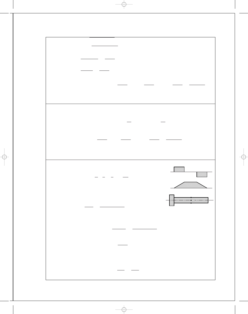
5-17
Design decisions required:
• Material and condition
• Design factor
• Failure model
• Diameter of pin
Using F
= 416 lbf from Ex. 5-3
σ
max
=
32M
πd
3
d
=
32M
πσ
max
1
/
3
Decision 1: Select the same material and condition of Ex. 5-3 (AISI 1035 steel, S
y
=
81 000)
.
Decision 2: Since we prefer the pin to yield, set n
d
a little larger than 1. Further explana-
tion will follow.
Decision 3: Use the Distortion Energy static failure theory.
Decision 4: Initially set n
d
= 1
σ
max
=
S
y
n
d
=
S
y
1
= 81 000 psi
d
=
32(416)(15)
π(81 000)
1
/
3
= 0.922 in
Choose preferred size of d
= 1.000 in
F
=
π(1)
3
(81 000)
32(15)
= 530 lbf
n
=
530
416
= 1.274
Set design factor to n
d
= 1.274
Adequacy Assessment:
σ
max
=
S
y
n
d
=
81 000
1
.274
= 63 580 psi
d
=
32(416)(15)
π(63 580)
1
/
3
= 1.000 in (OK )
F
=
π(1)
3
(81 000)
32(15)
= 530 lbf
n
=
530
416
= 1.274 (OK)
budynas_SM_ch05.qxd 11/29/2006 15:00 Page 129
FIRST PAGES
130
Solutions Manual • Instructor’s Solution Manual to Accompany Mechanical Engineering Design
5-18
For a thin walled cylinder made of AISI 1018 steel, S
y
= 54 kpsi, S
ut
= 64 kpsi.
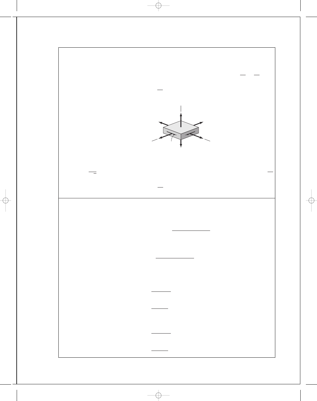
The state of stress is
σ
t
=
pd
4t
=
p(8)
4(0
.05)
= 40p, σ
l
=
pd
8t
= 20p, σ
r
= −p
These three are all principal stresses. Therefore,
σ
=
1
√
2
[(
σ
1
− σ
2
)
2
+ (σ
2
− σ
3
)
2
+ (σ
3
− σ
1
)
2
]
1
/
2
=
1
√
2
[(40 p
− 20p)
2
+ (20p + p)
2
+ (−p − 40p)
2
]
= 35.51p = 54 ⇒
p
= 1.52 kpsi (for yield) Ans.
For rupture, 35
.51p .= 64 ⇒ p .= 1.80 kpsi Ans.
5-19
For hot-forged AISI steel
w = 0.282 lbf/in
3
, S
y
= 30 kpsi and ν = 0.292. Then ρ = w/g =
0.282
/386 lbf · s
2
/in
; r
i
= 3 in; r
o
= 5 in; r
2
i
= 9; r
2
o
= 25; 3 + ν = 3.292; 1 + 3ν = 1.876.
Eq. (3-55) for r
= r
i
becomes
σ
t
= ρω
2
3
+ ν
8
2r
2
o
+ r
2
i
1
−
1
+ 3ν
3
+ ν
Rearranging and substituting the above values:
S
y
ω
2
=
0
.282
386
3
.292
8
50
+ 9
1
−
1
.876
3
.292
= 0.016 19
Setting the tangential stress equal to the yield stress,
ω =
30 000
0
.016 19
1
/
2
= 1361 rad/s
or
n
= 60ω/2π = 60(1361)/(2π)
= 13 000 rev/min
Now check the stresses at r
= (r
o
r
i
)
1
/
2
, or r
= [5(3)]
1
/
2
= 3.873 in
σ
r
= ρω
2
3
+ ν
8
(r
o
− r
i
)
2
=
0
.282ω
2
386
3
.292
8
(5
− 3)
2
= 0.001 203ω
2
Applying Eq. (3-55) for
σ
t
σ
t
= ω
2
0
.282
386
3
.292
8
9
+ 25 +
9(25)
15
−
1
.876(15)
3
.292
= 0.012 16ω
2
budynas_SM_ch05.qxd 11/29/2006 15:00 Page 130
FIRST PAGES
Chapter 5
131
Using the Distortion-Energy theory
σ
=
σ
2
t
− σ
r
σ
t
+ σ
2
r
1
/
2
= 0.011 61ω
2
Solving
ω =
30 000
0
.011 61
1
/
2
= 1607 rad/s
So the inner radius governs and n
= 13 000 rev/min Ans.
5-20
For a thin-walled pressure vessel,
d
i
= 3.5 − 2(0.065) = 3.37 in
σ
t
=
p(d
i
+ t)
2t
σ
t
=
500(3
.37 + 0.065)
2(0
.065)
= 13 212 psi
σ
l
=
pd
i
4t
=
500(3
.37)
4(0
.065)
= 6481 psi
σ
r
= −p
i
= −500 psi
These are all principal stresses, thus,
σ
=
1
√
2
{(13 212 − 6481)
2
+ [6481 − (−500)]
2
+ (−500 − 13 212)
2
}
1
/
2
σ
= 11 876 psi
n
=
S
y
σ
=
46 000
σ
=
46 000
11 876
= 3.87 Ans.
5-21
Table A-20 gives S
y
as 320 MPa. The maximum significant stress condition occurs at r
i
where
σ
1
= σ
r
= 0, σ
2
= 0, and σ
3
= σ
t
. From Eq. (3-49) for r = r
i
, p
i
= 0,
σ
t
= −
2r
2
o
p
o
r
2
o
− r
2
i
= −
2(150
2
) p
o
150
2
− 100
2
= −3.6p
o
σ
= 3.6p
o
= S
y
= 320
p
o
=
320
3
.6
= 88.9 MPa Ans.
5-22
S
ut
= 30 kpsi, w = 0.260 lbf/in
3
,
ν = 0.211, 3 + ν = 3.211, 1 + 3ν = 1.633. At the inner
radius, from Prob. 5-19
σ
t
ω
2
= ρ
3
+ ν
8
2r
2
o
+ r
2
i
−
1
+ 3ν
3
+ ν
r
2
i
budynas_SM_ch05.qxd 11/29/2006 15:00 Page 131
FIRST PAGES
132
Solutions Manual • Instructor’s Solution Manual to Accompany Mechanical Engineering Design
Here r
2
o
= 25, r
2
i
= 9, and so
σ
t
ω
2
=
0
.260
386
3
.211
8
50
+ 9 −
1
.633(9)
3
.211
= 0.0147
Since
σ
r
is of the same sign, we use M2M failure criteria in the first quadrant. From Table
A-24, S
ut
= 31 kpsi, thus,
ω =
31 000
0
.0147
1
/
2
= 1452 rad/s
rpm
= 60ω/(2π) = 60(1452)/(2π)
= 13 866 rev/min
Using the grade number of 30 for S
ut
= 30 000 kpsi gives a bursting speed of 13640 rev/min.
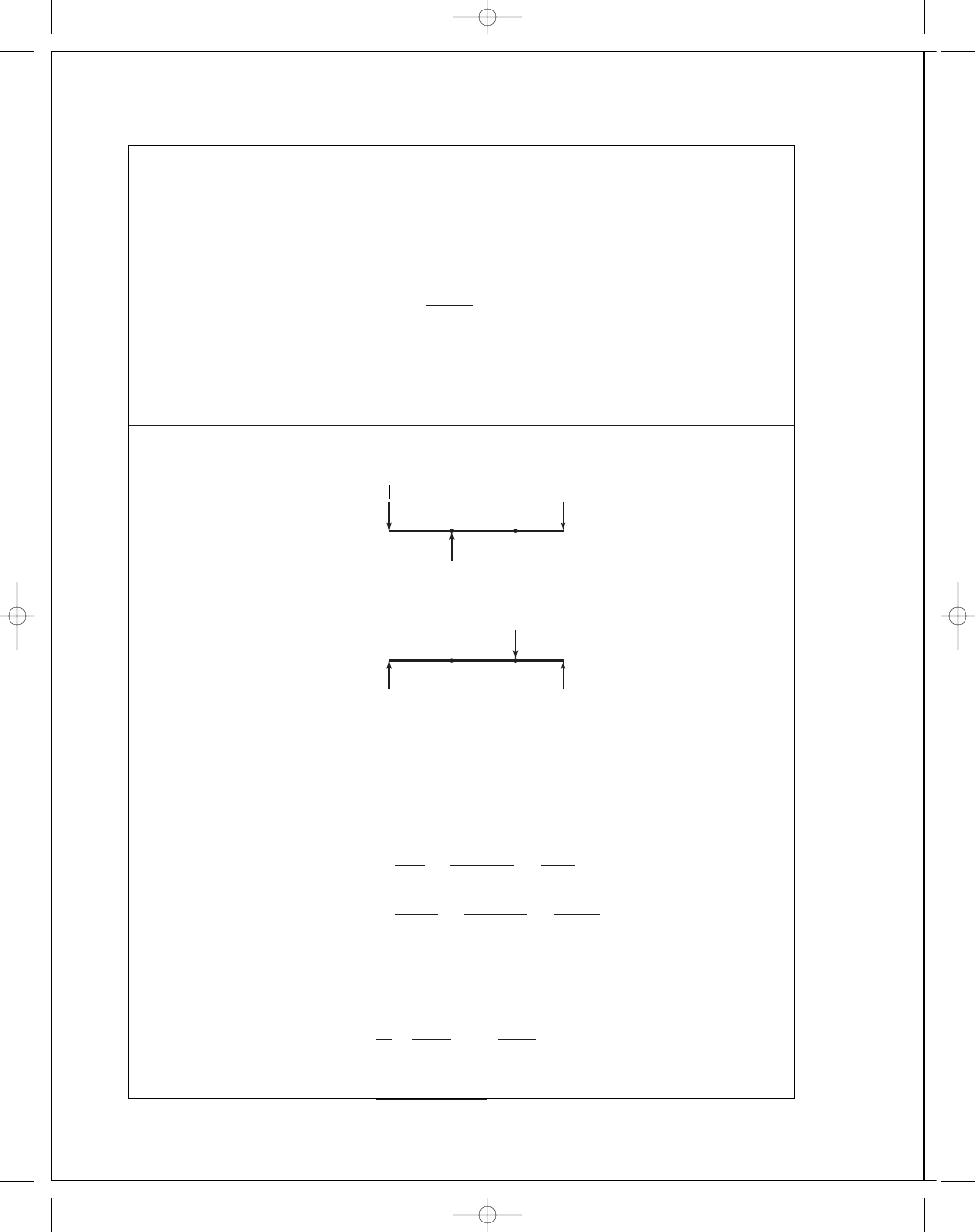
5-23
T
C
= (360 − 27)(3) = 1000 lbf · in, T
B
= (300 − 50)(4) = 1000 lbf · in
In x y plane, M
B
= 223(8) = 1784 lbf · in and M
C
= 127(6) = 762 lbf · in.
In the x z plane, M
B
= 848 lbf · in and M
C
= 1686 lbf · in. The resultants are
M
B
= [(1784)
2
+ (848)
2
]
1
/
2
= 1975 lbf · in
M
C
= [(1686)
2
+ (762)
2
]
1
/
2
= 1850 lbf · in
So point B governs and the stresses are
τ
x y
=
16T
πd
3
=
16(1000)
πd
3
=
5093
d
3
psi
σ
x
=
32M
B
πd
3
=
32(1975)
πd
3
=
20 120
d
3
psi
Then
σ
A
,
σ
B
=
σ
x
2
±
σ
x
2
2
+ τ
2
x y
1
/
2
σ
A
,
σ
B
=
1
d
3
20
.12
2
±
20
.12
2
2
+ (5.09)
2
1
/
2
=
(10
.06 ± 11.27)
d
3
kpsi
· in
3
B
A
D
C
xz plane
106 lbf
8"
8"
6"
281 lbf
387 lbf
B
A
D
C
223 lbf
8"
8"
6"
350 lbf
127 lbf
xy plane
y
budynas_SM_ch05.qxd 11/29/2006 15:00 Page 132
FIRST PAGES
Chapter 5
133
Then
σ
A
=
10
.06 + 11.27
d
3
=
21
.33
d
3
kpsi
and
σ
B
=
10
.06 − 11.27
d
3
= −
1
.21
d
3
kpsi
For this state of stress, use the Brittle-Coulomb-Mohr theory for illustration. Here we use
S
ut
(min)
= 25 kpsi, S
uc
(min)
= 97 kpsi, and Eq. (5-31b) to arrive at
21
.33
25d
3
−
−1.21
97d
3
=
1
2
.8
Solving gives d
= 1.34 in. So use d = 1 3/8 in Ans.
Note that this has been solved as a statics problem. Fatigue will be considered in the next
chapter.
5-24
As in Prob. 5-23, we will assume this to be statics problem. Since the proportions are un-
changed, the bearing reactions will be the same as in Prob. 5-23. Thus
x y plane:
M
B
= 223(4) = 892 lbf · in
x z plane:
M
B
= 106(4) = 424 lbf · in
So
M
max
= [(892)
2
+ (424)
2
]
1
/
2
= 988 lbf · in
σ
x
=
32M
B
πd
3
=
32(988)
πd
3
=
10 060
d
3
psi
Since the torsional stress is unchanged,
τ
x z
= 5.09/d
3
kpsi
σ
A
,
σ
B
=
1
d
3
10
.06
2
±
10
.06
2
2
+ (5.09)
2
1
/
2
σ
A
= 12.19/d
3
and
σ
B
= −2.13/d
3
Using the Brittle-Coulomb-Mohr, as was used in Prob. 5-23, gives
12
.19
25d
3
−
−2.13
97d
3
=
1
2
.8
Solving gives d
= 1 1/8 in. Ans.
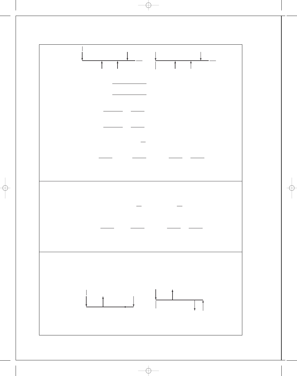
5-25
( F
A
)
t
= 300 cos 20 = 281.9 lbf, (F
A
)
r
= 300 sin 20 = 102.6 lbf
T
= 281.9(12) = 3383 lbf · in, (F
C
)
t
=
3383
5
= 676.6 lbf
( F
C
)
r
= 676.6 tan 20 = 246.3 lbf
budynas_SM_ch05.qxd 11/29/2006 15:00 Page 133
FIRST PAGES
134
Solutions Manual • Instructor’s Solution Manual to Accompany Mechanical Engineering Design
M
A
= 20
193
.7
2
+ 233.5
2
= 6068 lbf · in
M
B
= 10
246
.3
2
+ 676.6
2
= 7200 lbf · in (maximum)
σ
x
=
32(7200)
πd
3
=
73 340
d
3
τ
x y
=
16(3383)
πd
3
=
17 230
d
3
σ
=
σ
2
x
+ 3τ
2
x y
1
/
2
=
S
y
n
73 340
d
3
2
+ 3
17 230
d
3
2
1
/
2
=
79 180
d
3
=
60 000
3
.5
d
= 1.665 in so use a standard diameter size of 1.75 in Ans.
5-26
From Prob. 5-25,
τ
max
=
σ
x
2
2
+ τ
2
x y
1
/
2
=
S
y
2n
73 340
2d
3
2
+
17 230
d
3
2
1
/
2
=
40 516
d
3
=
60 000
2(3
.5)
d
= 1.678 in so use 1.75 in Ans.
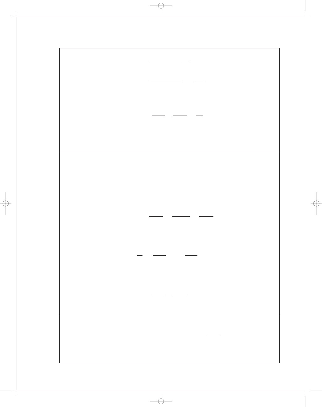
5-27
T
= (270 − 50)(0.150) = 33 N · m, S
y
= 370 MPa
(T
1
− 0.15T
1
)(0
.125) = 33 ⇒ T
1
= 310.6 N, T
2
= 0.15(310.6) = 46.6 N
(T
1
+ T
2
) cos 45
= 252.6 N
xz plane
z
107.0 N
174.4 N
252.6 N
320 N
300
400
150
y
163.4 N
89.2 N
252.6 N
300
400
150
xy plane
A
B
C
O
xy plane
x
y
A
B
C
R
Oy
= 193.7 lbf
R
By
= 158.1 lbf
281.9 lbf
20"
16"
10"
246.3 lbf
O
xz plane
x
z
A
B
C
R
Oz
= 233.5 lbf
R
Bz
= 807.5 lbf
O
102.6 lbf
20"
16"
10"
676.6 lbf
budynas_SM_ch05.qxd 11/29/2006 15:00 Page 134
FIRST PAGES
Chapter 5
135
M
A
= 0.3
163
.4
2
+ 107
2
= 58.59 N · m
(maximum)
M
B
= 0.15
89
.2
2
+ 174.4
2
= 29.38 N · m
σ
x
=
32(58
.59)
πd
3
=
596
.8
d
3
τ
x y
=
16(33)
πd
3
=
168
.1
d
3
σ
=
σ
2
x
+ 3τ
2
x y
1
/
2
=
596
.8
d
3
2
+ 3
168
.1
d
3
2
1
/
2
=
664
.0
d
3
=
370(10
6
)
3
.0
d
= 17.5(10
−
3
) m
= 17.5 mm,
so use 18 mm
Ans.
5-28
From Prob. 5-27,
τ
max
=
σ
x
2
2
+ τ
2
x y
1
/
2
=
S
y
2n
596
.8
2d
3
2
+
168
.1
d
3
2
1
/
2
=
342
.5
d
3
=
370(10
6
)
2(3
.0)
d
= 17.7(10
−
3
) m
= 17.7 mm, so use 18 mm Ans.
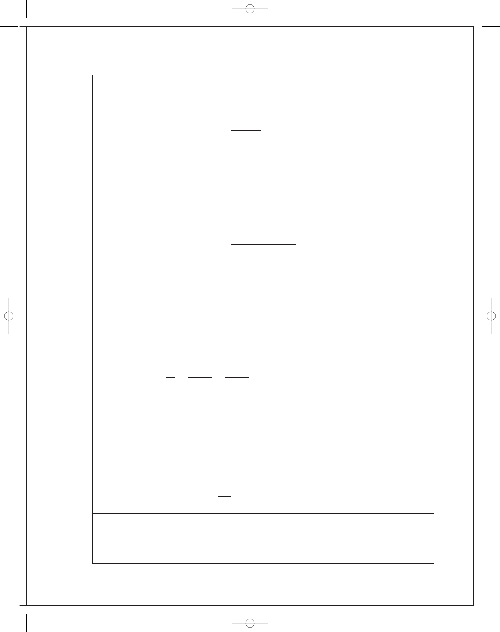
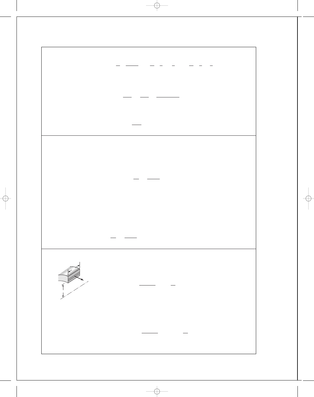
5-29
For the loading scheme shown in Figure (c),
M
max
=
F
2
a
2
+
b
4
=
4
.4
2
(6
+ 4.5)
= 23.1 N · m
For a stress element at A:
σ
x
=
32M
πd
3
=
32(23
.1)(10
3
)
π(12)
3
= 136.2 MPa
The shear at C is
τ
x y
=
4( F
/2)
3
πd
2
/4
=
4(4
.4/2)(10
3
)
3
π(12)
2
/4
= 25.94 MPa
τ
max
=
136
.2
2
2
1
/
2
= 68.1 MPa
Since S
y
= 220 MPa, S
sy
= 220/2 = 110 MPa, and
n
=
S
sy
τ
max
=
110
68
.1
= 1.62 Ans.
x
y
A
B
V
M
C
budynas_SM_ch05.qxd 11/29/2006 15:00 Page 135
FIRST PAGES
136
Solutions Manual • Instructor’s Solution Manual to Accompany Mechanical Engineering Design
For the loading scheme depicted in Figure (d )
M
max
=
F
2
a
+ b
2
−
F
2
1
2
b
2
2
=
F
2
a
2
+
b
4
This result is the same as that obtained for Figure (c). At point B, we also have a surface
compression of
σ
y
=
−F
A
=
−F
bd
−
−4.4(10
3
)
18(12)
= −20.4 MPa
With
σ
x
= −136.2 MPa. From a Mohrs circle diagram, τ
max
= 136.2/2 = 68.1 MPa.
n
=
110
68
.1
= 1.62 MPa Ans.
5-30
Based on Figure (c) and using Eq. (5-15)
σ
=
σ
2
x
1
/
2
= (136.2
2
)
1
/
2
= 136.2 MPa
n
=
S
y
σ
=
220
136
.2
= 1.62 Ans.
Based on Figure (d) and using Eq. (5-15) and the solution of Prob. 5-29,
σ
=
σ
2
x
− σ
x
σ
y
+ σ
2
y
1
/
2
= [(−136.2)
2
− (−136.2)(−20.4) + (−20.4)
2
]
1
/
2
= 127.2 MPa
n
=
S
y
σ
=
220
127
.2
= 1.73 Ans.
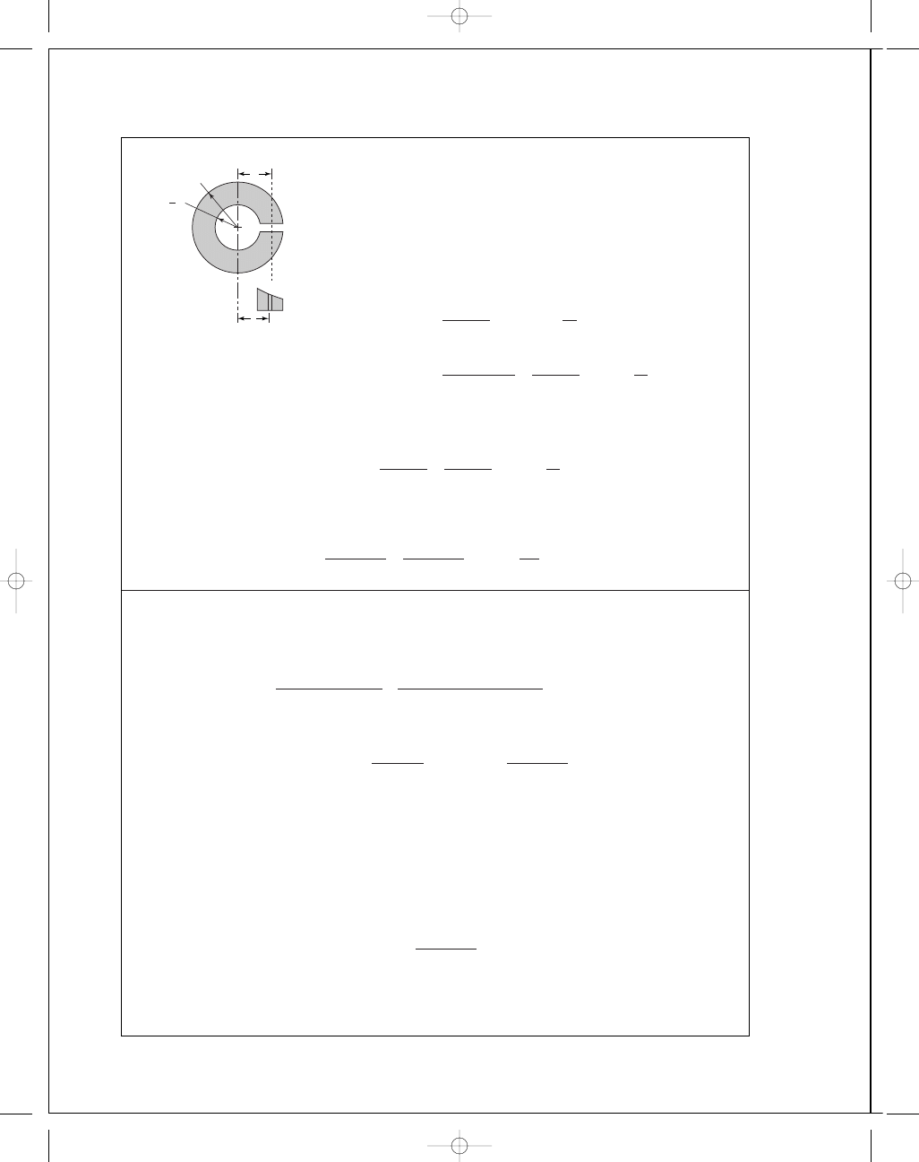
5-31
When the ring is set, the hoop tension in the ring is
equal to the screw tension.
σ
t
=
r
2
i
p
i
r
2
o
− r
2
i
1
+
r
2
o
r
2
We have the hoop tension at any radius. The differential hoop tension d F is
d F
= wσ
t
dr
F
=
r
o
r
i
wσ
t
dr
=
wr
2
i
p
i
r
2
o
− r
2
i
r
o
r
i
1
+
r
2
o
r
2
dr
= wr
i
p
i
(1)
dF
r
w
budynas_SM_ch05.qxd 11/29/2006 15:00 Page 136
FIRST PAGES
Chapter 5
137
The screw equation is
F
i
=
T
0
.2d
(2)
From Eqs. (1) and (2)
p
i
=
F
wr
i
=
T
0
.2dwr
i
d F
x
= f p
i
r
i
d
θ
F
x
=
2
π
o
f p
i
wr
i
d
θ =
f T
w
0
.2dwr
i
r
i
2
π
o
d
θ
=
2
π f T
0
.2d
Ans.
5-32
(a) From Prob. 5-31,
T
= 0.2F
i
d
F
i
=
T
0
.2d
=
190
0
.2(0.25)
= 3800 lbf Ans.
(b) From Prob. 5-31,
F
= wr
i
p
i
p
i
=
F
wr
i
=
F
i
wr
i
=
3800
0
.5(0.5)
= 15 200 psi Ans.
(c)
σ
t
=
r
2
i
p
i
r
2
o
− r
2
i
1
+
r
2
o
r
r
=r
i
=
p
i
r
2
i
+ r
2
o
r
2
o
− r
2
i
=
15 200(0
.5
2
+ 1
2
)
1
2
− 0.5
2
= 25 333 psi Ans.
σ
r
= −p
i
= −15 200 psi
(d)
τ
max
=
σ
1
− σ
3
2
=
σ
t
− σ
r
2
=
25 333
− (−15 200)
2
= 20 267 psi Ans.
σ
=
σ
2
A
+ σ
2
B
− σ
A
σ
B
1
/
2
= [25 333
2
+ (−15 200)
2
− 25 333(−15 200)]
1
/
2
= 35 466 psi Ans.
(e) Maximum Shear hypothesis
n
=
S
sy
τ
max
=
0
.5S
y
τ
max
=
0
.5(63)
20
.267
= 1.55 Ans.
Distortion Energy theory
n
=
S
y
σ
=
63
35 466
= 1.78 Ans.
dF
x
p
i
r
i
d
budynas_SM_ch05.qxd 11/29/2006 15:00 Page 137
FIRST PAGES
138
Solutions Manual • Instructor’s Solution Manual to Accompany Mechanical Engineering Design
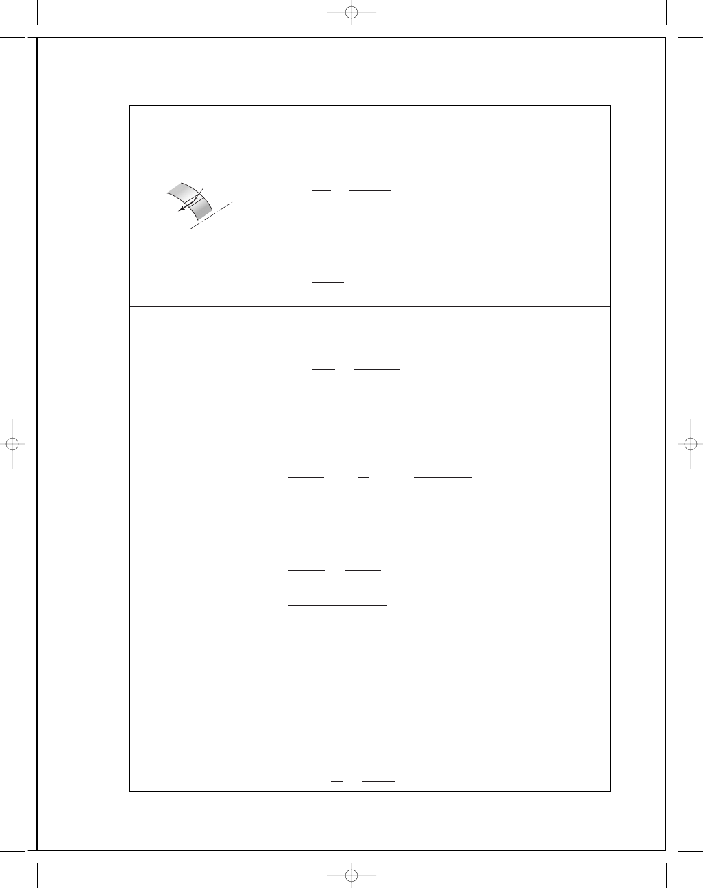
5-33
The moment about the center caused by force F
is Fr
e
where r
e
is the effective radius. This is
balanced by the moment about the center
caused by the tangential (hoop) stress.
Fr
e
=
r
o
r
i
r
σ
t
w dr
=
wp
i
r
2
i
r
2
o
− r
2
i
r
o
r
i
r
+
r
2
o
r
dr
r
e
=
wp
i
r
2
i
F
r
2
o
− r
2
i
r
2
o
− r
2
i
2
+ r
2
o
ln
r
o
r
i
From Prob. 5-31, F
= wr
i
p
i
. Therefore,
r
e
=
r
i
r
2
o
− r
2
i
r
2
o
− r
2
i
2
+ r
2
o
ln
r
o
r
i
For the conditions of Prob. 5-31, r
i
= 0.5 and r
o
= 1 in
r
e
=
0
.5
1
2
− 0.5
2
1
2
− 0.5
2
2
+ 1
2
ln
1
0
.5
= 0.712 in
5-34
δ
nom
= 0.0005 in
(a) From Eq. (3-57)
p
=
30(10
6
)(0
.0005)
(1
3
)
(1
.5
2
− 1
2
)(1
2
− 0.5
2
)
2(1
.5
2
− 0.5
2
)
= 3516 psi Ans.
Inner member:
Eq. (3-58)
(
σ
t
)
i
= −p
R
2
+ r
2
i
R
2
− r
2
i
= −3516
1
2
+ 0.5
2
1
2
− 0.5
2
= −5860 psi
(
σ
r
)
i
= −p = −3516 psi
Eq. (5-13)
σ
i
=
σ
2
A
− σ
A
σ
B
+ σ
2
B
1
/
2
= [(−5860)
2
− (−5860)(−3516) + (−3516)
2
]
1
/
2
= 5110 psi Ans.
Outer member:
Eq. (3-59)
(
σ
t
)
o
= 3516
1
.5
2
+ 1
2
1
.5
2
− 1
2
= 9142 psi
(
σ
r
)
o
= −p = −3516 psi
Eq. (5-13)
σ
o
= [9142
2
− 9142(−3516) + (−3516)
2
]
1
/
2
= 11 320 psi Ans.
R
t
1
2
"
1"R
r
e
r
budynas_SM_ch05.qxd 11/29/2006 15:00 Page 138
FIRST PAGES
Chapter 5
139
(b) For a solid inner tube,
p
=
30(10
6
)(0
.0005)
1
(1
.5
2
− 1
2
)(1
2
)
2(1
2
)(1
.5
2
)
= 4167 psi Ans.
(
σ
t
)
i
= −p = −4167 psi, (σ
r
)
i
= −4167 psi
σ
i
= [(−4167)
2
− (−4167)(−4167) + (−4167)
2
]
1
/
2
= 4167 psi Ans.
(
σ
t
)
o
= 4167
1
.5
2
+ 1
2
1
.5
2
− 1
2
= 10 830 psi, (σ
r
)
o
= −4167 psi
σ
o
= [10 830
2
− 10 830(−4167) + (−4167)
2
]
1
/
2
= 13 410 psi Ans.
5-35
Using Eq. (3-57) with diametral values,
p
=
207(10
3
)(0
.02)
(50
3
)
(75
2
− 50
2
)(50
2
− 25
2
)
2(75
2
− 25
2
)
= 19.41 MPa Ans.
Eq. (3-58)
(
σ
t
)
i
= −19.41
50
2
+ 25
2
50
2
− 25
2
= −32.35 MPa
(
σ
r
)
i
= −19.41 MPa
Eq. (5-13)
σ
i
= [(−32.35)
2
− (−32.35)(−19.41) + (−19.41)
2
]
1
/
2
= 28.20 MPa Ans.
Eq. (3-59)
(
σ
t
)
o
= 19.41
75
2
+ 50
2
75
2
− 50
2
= 50.47 MPa,
(
σ
r
)
o
= −19.41 MPa
σ
o
= [50.47
2
− 50.47(−19.41) + (−19.41)
2
]
1
/
2
= 62.48 MPa Ans.
5-36
Max. shrink-fit conditions: Diametral interference
δ
d
= 50.01 − 49.97 = 0.04 mm. Equa-
tion (3-57) using diametral values:
p
=
207(10
3
)0
.04
50
3
(75
2
− 50
2
)(50
2
− 25
2
)
2(75
2
− 25
2
)
= 38.81 MPa
Ans.
Eq. (3-58):
(
σ
t
)
i
= −38.81
50
2
+ 25
2
50
2
− 25
2
= −64.68 MPa
(
σ
r
)
i
= −38.81 MPa
Eq. (5-13):
σ
i
=
(
−64.68)
2
− (−64.68)(−38.81) + (−38.81)
2
1
/
2
= 56.39 MPa
Ans.
budynas_SM_ch05.qxd 11/29/2006 15:00 Page 139
FIRST PAGES
140
Solutions Manual • Instructor’s Solution Manual to Accompany Mechanical Engineering Design
5-37
δ =
1
.9998
2
−
1
.999
2
= 0.0004 in
Eq. (3-56)
0
.0004 =
p(1)
14
.5(10
6
)
2
2
+ 1
2
2
2
− 1
2
+ 0.211
+
p(1)
30(10
6
)
1
2
+ 0
1
2
− 0
− 0.292
p
= 2613 psi
Applying Eq. (4-58) at R,
(
σ
t
)
o
= 2613
2
2
+ 1
2
2
2
− 1
2
= 4355 psi
(
σ
r
)
o
= −2613 psi, S
ut
= 20 kpsi, S
uc
= 83 kpsi
σ
o
σ
A
=
2613
4355
< 1,
∴
use Eq. (5-32a)
h
= S
ut
/σ
A
= 20/4.355 = 4.59 Ans.
5-38
E
= 30(10
6
) psi,
ν = 0.292, I = (π/64)(2
4
− 1.5
4
)
= 0.5369 in
4
Eq. (3-57) can be written in terms of diameters,
p
=
E
δ
d
D
d
2
o
− D
2
D
2
− d
2
i
2D
2
d
2
o
− d
2
i
=
30(10
6
)
1
.75
(0
.002 46)
(2
2
− 1.75
2
)(1
.75
2
− 1.5
2
)
2(1
.75
2
)(2
2
− 1.5
2
)
= 2997 psi = 2.997 kpsi
Outer member:
Outer radius:
(
σ
t
)
o
=
1
.75
2
(2
.997)
2
2
− 1.75
2
(2)
= 19.58 kpsi, (σ
r
)
o
= 0
Inner radius:
(
σ
t
)
i
=
1
.75
2
(2
.997)
2
2
− 1.75
2
1
+
2
2
1
.75
2
= 22.58 kpsi, (σ
r
)
i
= −2.997 kpsi
Bending:
r
o
:
(
σ
x
)
o
=
6
.000(2/2)
0
.5369
= 11.18 kpsi
r
i
:
(
σ
x
)
i
=
6
.000(1.75/2)
0
.5369
= 9.78 kpsi
Torsion:
J
= 2I = 1.0738 in
4
r
o
:
(
τ
x y
)
o
=
8
.000(2/2)
1
.0738
= 7.45 kpsi
r
i
:
(
τ
x y
)
i
=
8
.000(1.75/2)
1
.0738
= 6.52 kpsi
budynas_SM_ch05.qxd 11/29/2006 15:00 Page 140
FIRST PAGES
Chapter 5
141
Outer radius is plane stress
σ
x
= 11.18 kpsi, σ
y
= 19.58 kpsi, τ
x y
= 7.45 kpsi
Eq. (5-15)
σ
= [11.18
2
− (11.18)(19.58) + 19.58
2
+ 3(7.45
2
)]
1
/
2
=
S
y
n
o
=
60
n
o
21
.35 =
60
n
o
⇒ n
o
= 2.81 Ans.
Inner radius, 3D state of stress
From Eq. (5-14) with
τ
yz
= τ
zx
= 0
σ
=
1
√
2
[(9
.78 − 22.58)
2
+ (22.58 + 2.997)
2
+ (−2.997 − 9.78)
2
+ 6(6.52)
2
]
1
/
2
=
60
n
i
24
.86 =
60
n
i
⇒ n
i
= 2.41 Ans.
5-39
From Prob. 5-38: p
= 2.997 kpsi, I = 0.5369 in
4
, J
= 1.0738 in
4
Inner member:
Outer radius:
(
σ
t
)
o
= −2.997
(0
.875
2
+ 0.75
2
)
(0
.875
2
− 0.75
2
)
= −19.60 kpsi
(
σ
r
)
o
= −2.997 kpsi
Inner radius:
(
σ
t
)
i
= −
2(2
.997)(0.875
2
)
0
.875
2
− 0.75
2
= −22.59 kpsi
(
σ
r
)
i
= 0
Bending:
r
o
:
(
σ
x
)
o
=
6(0
.875)
0
.5369
= 9.78 kpsi
r
i
:
(
σ
x
)
i
=
6(0
.75)
0
.5369
= 8.38 kpsi
Torsion:
r
o
:
(
τ
x y
)
o
=
8(0
.875)
1
.0738
= 6.52 kpsi
r
i
:
(
τ
x y
)
i
=
8(0
.75)
1
.0738
= 5.59 kpsi
y
x
—2.997 kpsi
9.78 kpsi
22.58 kpsi
6.52 kpsi
z
budynas_SM_ch05.qxd 11/29/2006 15:00 Page 141
FIRST PAGES
142
Solutions Manual • Instructor’s Solution Manual to Accompany Mechanical Engineering Design
The inner radius is in plane stress:
σ
x
= 8.38 kpsi, σ
y
= −22.59 kpsi, τ
x y
= 5.59 kpsi
σ
i
= [8.38
2
− (8.38)(−22.59) + (−22.59)
2
+ 3(5.59
2
)]
1
/
2
= 29.4 kpsi
n
i
=
S
y
σ
i
=
60
29
.4
= 2.04 Ans.
Outer radius experiences a radial stress,
σ
r
σ
o
=
1
√
2
(
−19.60 + 2.997)
2
+ (−2.997 − 9.78)
2
+ (9.78 + 19.60)
2
+ 6(6.52)
2
1
/
2
= 27.9 kpsi
n
o
=
60
27
.9
= 2.15 Ans.
5-40
σ
p
=
1
2
2
K
I
√
2
πr
cos
θ
2
±
K
I
√
2
πr
sin
θ
2
cos
θ
2
sin
3
θ
2
2
+
K
I
√
2
πr
sin
θ
2
cos
θ
2
cos
3
θ
2
2
1
/
2
=
K
I
√
2
πr
cos
θ
2
±
sin
2
θ
2
cos
2
θ
2
sin
2
3
θ
2
+ sin
2
θ
2
cos
2
θ
2
cos
2
3
θ
2
1
/
2
=
K
I
√
2
πr
cos
θ
2
± cos
θ
2
sin
θ
2
=
K
I
√
2
πr
cos
θ
2
1
± sin
θ
2
Plane stress: The third principal stress is zero and
σ
1
=
K
I
√
2
πr
cos
θ
2
1
+ sin
θ
2
,
σ
2
=
K
I
√
2
πr
cos
θ
2
1
− sin
θ
2
,
σ
3
= 0 Ans.
Plane strain:
σ
1
and
σ
2
equations still valid however,
σ
3
= ν(σ
x
+ σ
y
)
= 2ν
K
I
√
2
πr
cos
θ
2
Ans.
5-41
For
θ = 0 and plane strain, the principal stress equations of Prob. 5-40 give
σ
1
= σ
2
=
K
I
√
2
πr
,
σ
3
= 2ν
K
I
√
2
πr
= 2νσ
1
(a) DE:
1
√
2
[(
σ
1
− σ
1
)
2
+ (σ
1
− 2νσ
1
)
2
+ (2νσ
1
− σ
1
)
2
]
1
/
2
= S
y
σ
1
− 2νσ
1
= S
y
For
ν =
1
3
,
1
− 2
1
3
σ
1
= S
y
⇒ σ
1
= 3S
y
Ans.
budynas_SM_ch05.qxd 11/29/2006 15:00 Page 142
FIRST PAGES
Chapter 5
143
(b) MSS:
σ
1
− σ
3
= S
y
⇒ σ
1
− 2νσ
1
= S
y
ν =
1
3
⇒ σ
1
= 3S
y
Ans.
σ
3
=
2
3
σ
1
Radius of largest circle
R
=
1
2
σ
1
−
2
3
σ
1
=
σ
1
6
5-42
(a) Ignoring stress concentration
F
= S
y
A
= 160(4)(0.5) = 320 kips Ans.
(b) From Fig. 6-36: h
/b = 1, a/b = 0.625/4 = 0.1563, β = 1.3
Eq. (6-51)
70
= 1.3
F
4(0
.5)
π(0.625)
F
= 76.9 kips Ans.
5-43
Given: a
= 12.5 mm, K
I c
= 80 MPa ·
√
m, S
y
= 1200 MPa, S
ut
= 1350 MPa
r
o
=
350
2
= 175 mm, r
i
=
350
− 50
2
= 150 mm
a
/(r
o
− r
i
)
=
12
.5
175
− 150
= 0.5
r
i
/r
o
=
150
175
= 0.857
Fig. 5-30:
β .= 2.5
Eq. (5-37):
K
I c
= βσ
√
πa
80
= 2.5σ
π(0.0125)
σ = 161.5 MPa
Eq. (3-50) at r
= r
o
:
σ
t
=
r
2
i
p
i
r
2
o
− r
2
i
(2)
161
.5 =
150
2
p
i
(2)
175
2
− 150
2
p
i
= 29.2 MPa Ans.
1
,
2
1
2
3
budynas_SM_ch05.qxd 11/29/2006 15:00 Page 143
FIRST PAGES
144
Solutions Manual • Instructor’s Solution Manual to Accompany Mechanical Engineering Design
5-44
(a) First convert the data to radial dimensions to agree with the formulations of Fig. 3-33.
Thus
r
o
= 0.5625 ± 0.001in
r
i
= 0.1875 ± 0.001 in
R
o
= 0.375 ± 0.0002 in
R
i
= 0.376 ± 0.0002 in
The stochastic nature of the dimensions affects the
δ = |R
i
| − |R
o
| relation in
Eq. (3-57) but not the others. Set R
= (1/2)(R
i
+ R
o
)
= 0.3755. From Eq. (3-57)
p
=
E
δ
R
r
2
o
− R
2
R
2
− r
2
i
2R
2
r
2
o
− r
2
i
Substituting and solving with E
= 30 Mpsi gives
p
= 18.70(10
6
)
δ
Since
δ = R
i
− R
o
¯δ = ¯R
i
− ¯R
o
= 0.376 − 0.375 = 0.001 in
and
ˆσ
δ
=
0
.0002
4
2
+
0
.0002
4
2
1
/
2
= 0.000 070 7 in
Then
C
δ
=
ˆσ
δ
¯δ
=
0
.000 070 7
0
.001
= 0.0707
The tangential inner-cylinder stress at the shrink-fit surface is given by
σ
i t
= −p
¯R
2
+ ¯r
2
i
¯R
2
− ¯r
2
i
= −18.70(10
6
)
δ
0
.3755
2
+ 0.1875
2
0
.3755
2
− 0.1875
2
= −31.1(10
6
)
δ
¯σ
i t
= −31.1(10
6
) ¯
δ = −31.1(10
6
)(0
.001)
= −31.1(10
3
) psi
Also
ˆσ
σ
i t
= |C
δ
¯σ
i t
| = 0.0707(−31.1)10
3
= 2899 psi
σ
i t
= N(−31 100, 2899) psi Ans.
budynas_SM_ch05.qxd 11/29/2006 15:00 Page 144
FIRST PAGES
Chapter 5
145
(b) The tangential stress for the outer cylinder at the shrink-fit surface is given by
σ
ot
= p
¯r
2
o
+ ¯R
2
¯r
2
o
− ¯R
2
= 18.70(10
6
)
δ
0
.5625
2
+ 0.3755
2
0
.5625
2
− 0.3755
2
= 48.76(10
6
)
δ psi
¯σ
ot
= 48.76(10
6
)(0
.001) = 48.76(10
3
) psi
ˆσ
σ
ot
= C
δ
¯σ
ot
= 0.0707(48.76)(10
3
)
= 34.45 psi
σ
ot
= N(48 760, 3445) psi Ans.
5-45
From Prob. 5-44, at the fit surface
σ
ot
= N(48.8, 3.45) kpsi. The radial stress is the fit
pressure which was found to be
p
= 18.70(10
6
)
δ
¯p = 18.70(10
6
)(0
.001) = 18.7(10
3
) psi
ˆσ
p
= C
δ
¯p = 0.0707(18.70)(10
3
)
= 1322 psi
and so
p
= N(18.7, 1.32) kpsi
and
σ
or
= −N(18.7, 1.32) kpsi
These represent the principal stresses. The von Mises stress is next assessed.
¯σ
A
= 48.8 kpsi,
¯σ
B
= −18.7 kpsi
k
= ¯σ
B
/ ¯σ
A
= −18.7/48.8 = −0.383
¯σ
= ¯σ
A
(1
− k + k
2
)
1
/
2
= 48.8[1 − (−0.383) + (−0.383)
2
]
1
/
2
= 60.4 kpsi
ˆσ
σ
= C
p
¯σ
= 0.0707(60.4) = 4.27 kpsi
Using the interference equation
z
= −
¯S − ¯σ
ˆσ
2
S
+ ˆσ
2
σ
1
/
2
= −
95
.5 − 60.4
[(6
.59)
2
+ (4.27)
2
]
1
/
2
= −4.5
p
f
= α = 0.000 003 40,
or about 3 chances in a million.
Ans.
budynas_SM_ch05.qxd 11/29/2006 15:00 Page 145

FIRST PAGES
146
Solutions Manual • Instructor’s Solution Manual to Accompany Mechanical Engineering Design
5-46
σ
t
=
pd
2t
=
6000N(1, 0
.083 33)(0.75)
2(0
.125)
= 18N(1, 0.083 33) kpsi
σ
l
=
pd
4t
=
6000N(1, 0
.083 33)(0.75)
4(0
.125)
= 9N(1, 0.083 33) kpsi
σ
r
= −p = −6000N(1, 0.083 33) kpsi
These three stresses are principal stresses whose variability is due to the loading. From
Eq. (5-12), we find the von Mises stress to be
σ
=
(18
− 9)
2
+ [9 − (−6)]
2
+ (−6 − 18)
2
2
1
/
2
= 21.0 kpsi
ˆσ
σ
= C
p
¯σ
= 0.083 33(21.0) = 1.75 kpsi
z
= −
¯S − ¯σ
ˆσ
2
S
+ ˆσ
2
σ
1
/
2
=
50
− 21.0
(4
.1
2
+ 1.75
2
)
1
/
2
= −6.5
The reliability is very high
R
= 1 − (6.5) = 1 − 4.02(10
−
11
) .
= 1 Ans.
budynas_SM_ch05.qxd 11/29/2006 15:00 Page 146
Wyszukiwarka
Podobne podstrony:
budynas SM ch01
budynas SM ch15
budynas SM ch16
budynas SM ch14
budynas SM ch12
budynas SM ch20
budynas SM ch09
budynas SM ch03
budynas SM ch10
budynas SM ch08
budynas SM ch11
budynas SM ch07
budynas SM ch04
więcej podobnych podstron