FIRST PAGES
Chapter 16
16-1
(a)
θ
1
= 0°, θ
2
= 120°, θ
a
= 90°, sin θ
a
= 1, a = 5 in
Eq. (16-2):
M
f
=
0
.28p
a
(1
.5)(6)
1
120°
0°
sin
θ(6 − 5 cos θ) dθ
= 17.96p
a
lbf
· in
Eq. (16-3): M
N
=
p
a
(1
.5)(6)(5)
1
120°
0°
sin
2
θ dθ = 56.87p
a
lbf
· in
c
= 2(5 cos 30
◦
)
= 8.66 in
Eq. (16-4):
F
=
56
.87p
a
− 17.96p
a
8
.66
= 4.49p
a
p
a
= F/4.49 = 500/4.49 = 111.4 psi for cw rotation
Eq. (16-7): 500
=
56
.87p
a
+ 17.96p
a
8
.66
p
a
= 57.9 psi for ccw rotation
A maximum pressure of 111
.4 psioccurs on the RH shoe for cw rotation. Ans.
(b) RH shoe:
Eq. (16-6):
T
R
=
0
.28(111.4)(1.5)(6)
2
(cos 0
◦
− cos 120
◦
)
1
= 2530 lbf · in Ans.
LH shoe:
Eq. (16-6):
T
L
=
0
.28(57.9)(1.5)(6)
2
(cos 0
◦
− cos 120
◦
)
1
= 1310 lbf · in Ans.
T
total
= 2530 + 1310 = 3840 lbf · in Ans.
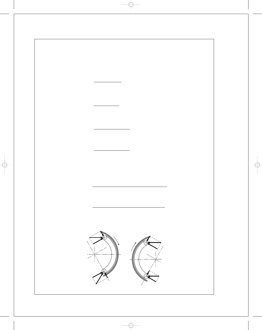
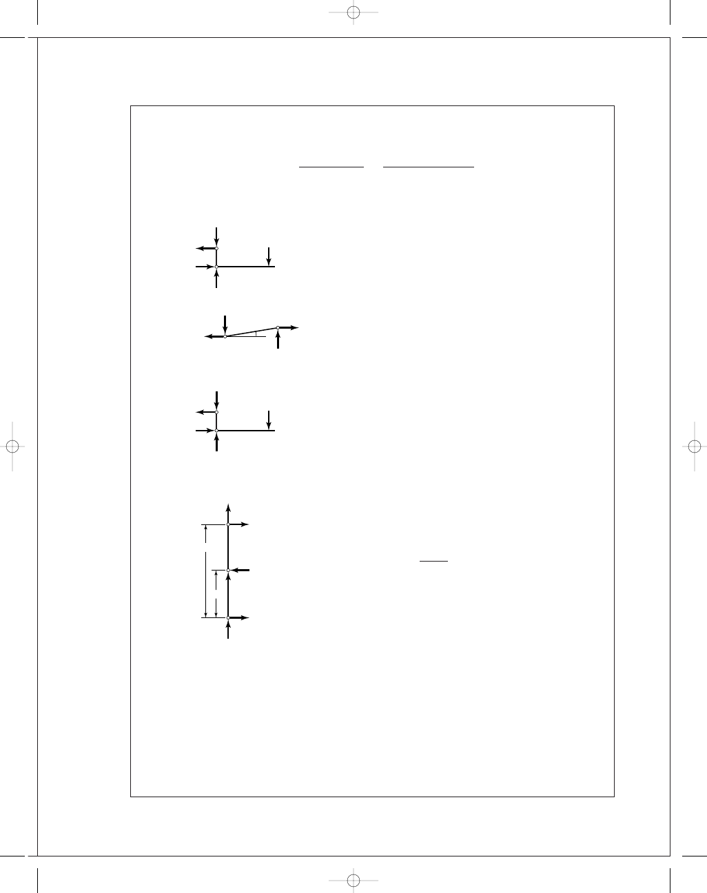
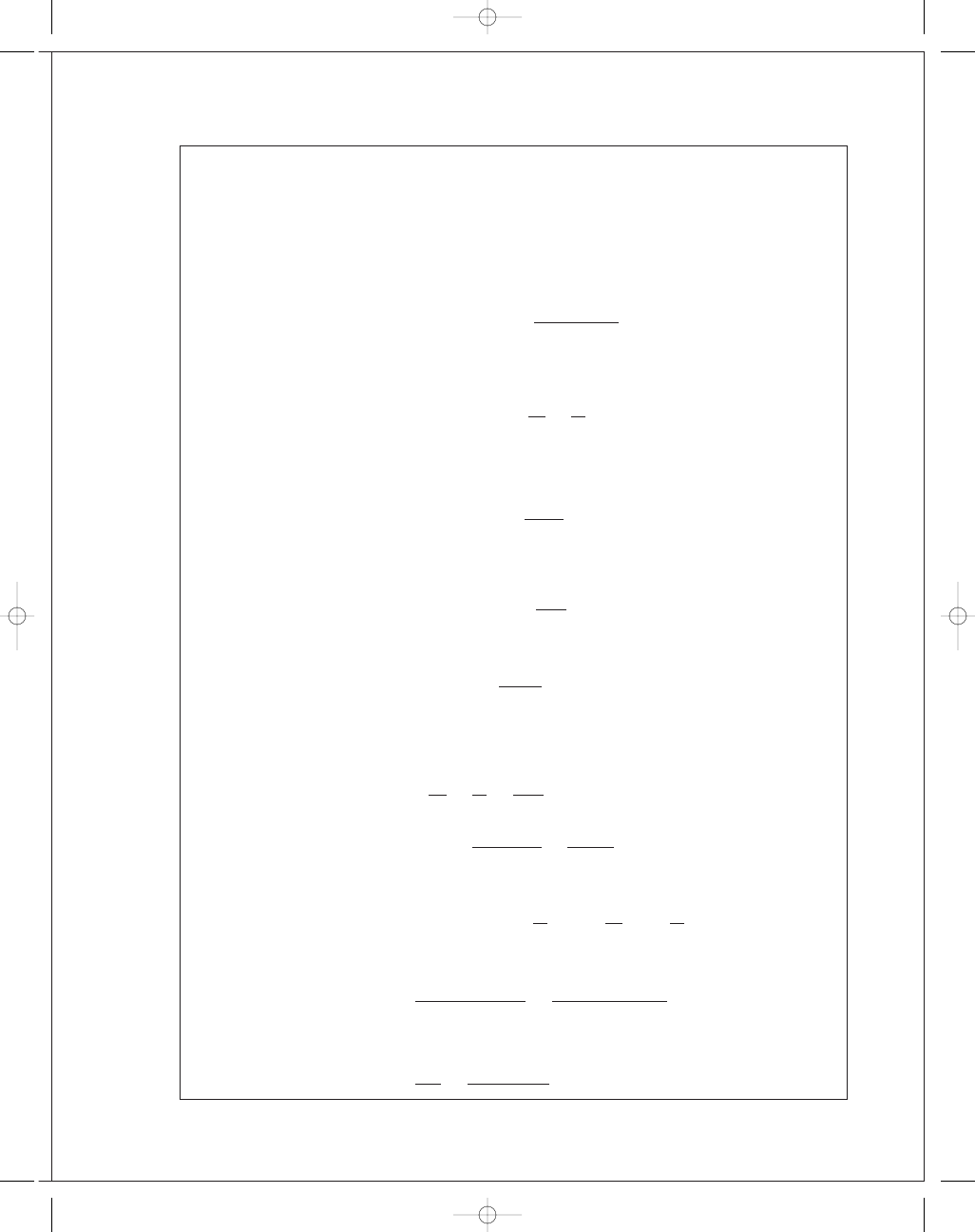
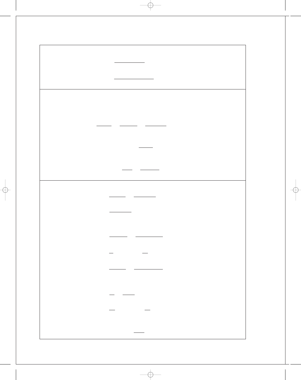
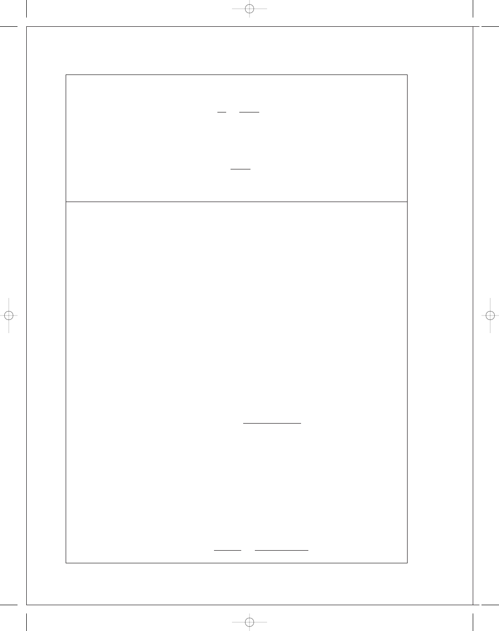
(c)
Force vectors not to scale
x
y
F
y
R
y
R
x
R
F
x
F
Secondary
shoe
30
⬚
y
x
R
x
F
y
F
x
F
R
y
R
Primary
shoe
30
⬚
budynas_SM_ch16.qxd 12/05/2006 17:45 Page 396

FIRST PAGES
Chapter 16
397
RH shoe:
F
x
= 500 sin 30° = 250 lbf,
F
y
= 500 cos 30° = 433 lbf
Eqs. (16-8):
A
=
1
2
sin
2
θ
120
◦
0
◦
= 0.375,
B
=
θ
2
−
1
4
sin 2
θ
2
π/
3 rad
0
= 1.264
Eqs. (16-9):
R
x
=
111
.4(1.5)(6)
1
[0
.375 − 0.28(1.264)] − 250 = −229 lbf
R
y
=
111
.4(1.5)(6)
1
[1
.264 + 0.28(0.375)] − 433 = 940 lbf
R
= [(−229)
2
+ (940)
2
]
1
/
2
= 967 lbf Ans.
LH shoe:
F
x
= 250 lbf,
F
y
= 433 lbf
Eqs. (16-10): R
x
=
57
.9(1.5)(6)
1
[0
.375 + 0.28(1.264)] − 250 = 130 lbf
R
y
=
57
.9(1.5)(6)
1
[1
.264 − 0.28(0.375)] − 433 = 171 lbf
R
= [(130)
2
+ (171)
2
]
1
/
2
= 215 lbf Ans.
16-2
θ
1
= 15°, θ
2
= 105°, θ
a
= 90°, sin θ
a
= 1, a = 5 in
Eq. (16-2):
M
f
=
0
.28p
a
(1
.5)(6)
1
105°
15°
sin
θ(6 − 5 cos θ) dθ = 13.06p
a
Eq. (16-3): M
N
=
p
a
(1
.5)(6)(5)
1
105°
15°
sin
2
θ dθ = 46.59p
a
c
= 2(5 cos 30°) = 8.66 in
Eq. (16-4):
F
=
46
.59p
a
− 13.06p
a
8
.66
= 3.872p
a
RH shoe:
p
a
= 500/3.872 = 129.1 psi on RH shoe for cw rotation Ans.
Eq. (16-6):
T
R
=
0
.28(129.1)(1.5)(6
2
)(cos 15°
− cos 105°)
1
= 2391 lbf · in
LH shoe:
500
=
46
.59p
a
+ 13.06p
a
8
.66
⇒
p
a
= 72.59 psi on LH shoe for ccw rotation Ans.
T
L
=
0
.28(72.59)(1.5)(6
2
)(cos 15°
− cos 105°)
1
= 1344 lbf · in
T
total
= 2391 + 1344 = 3735 lbf · in Ans.
Comparing this result with that of Prob. 16-1, a 2.7% reduction in torque is achieved by
using 25% less braking material.
budynas_SM_ch16.qxd 12/05/2006 17:45 Page 397

FIRST PAGES
398
Solutions Manual • Instructor’s Solution Manual to Accompany Mechanical Engineering Design
16-3
Given:
θ
1
= 0°, θ
2
= 120°, θ
a
= 90°, sin θ
a
= 1, a = R = 90 mm, f = 0.30,
F
= 1000 N = 1 kN, r = 280/2 = 140 mm, counter-clockwise rotation.
LH shoe:
M
f
=
f p
a
br
sin
θ
a
r (1
− cos θ
2
)
−
a
2
sin
2
θ
2
=
0
.30p
a
(0
.030)(0.140)
1
0
.140(1 − cos 120
◦
)
−
0
.090
2
sin
2
120°
= 0.000 222p
a
N
· m
M
N
=
p
a
br a
sin
θ
a
θ
2
2
−
1
4
sin 2
θ
2
=
p
a
(0
.030)(0.140)(0.090)
1
120°
2
π
180
−
1
4
sin 2(120°)
= 4.777(10
−
4
) p
a
N
· m
c
= 2r cos
180
◦
− θ
2
2
= 2(0.090) cos 30
◦
= 0.155 88 m
F
= 1 = p
a
4
.777(10
−
4
)
− 2.22(10
−
4
)
0
.155 88
= 1.64(10
−
3
) p
a
p
a
= 1/1.64(10
−
3
)
= 610 kPa
T
L
=
f p
a
br
2
(cos
θ
1
− cos θ
2
)
sin
θ
a
=
0
.30(610)(10
3
)(0
.030)(0.140
2
)
1
[1
− (−0.5)]
= 161.4 N · m Ans.
RH shoe:
M
f
= 2.22(10
−
4
) p
a
N
· m
M
N
= 4.77(10
−
4
) p
a
N
· m
c
= 0.155 88 m
F
= 1 = p
a
4
.77(10
−
4
)
+ 2.22(10
−
4
)
0
.155 88
= 4.49(10
−
3
) p
a
p
a
=
1
4
.49(10
−
3
)
= 222.8 kPa Ans.
T
R
= (222.8/610)(161.4) = 59.0 N · m Ans.
budynas_SM_ch16.qxd 12/05/2006 17:45 Page 398

FIRST PAGES
Chapter 16
399
16-4
(a) Given:
θ
1
= 10°, θ
2
= 75°, θ
a
= 75°, p
a
= 10
6
Pa,
f
= 0.24,
b
= 0.075 m (shoe width), a = 0.150 m, r = 0.200 m, d = 0.050 m, c = 0.165 m.
Some of the terms needed are evaluated as:
A
=
r
θ
2
θ
1
sin
θ dθ − a
θ
2
θ
1
sin
θ cos θ dθ
= r
−cos θ
θ
2
θ
1
− a
1
2
sin
2
θ
θ
2
θ
1
= 200
−cos θ
75°
10°
− 150
1
2
sin
2
θ
75°
10°
= 77.5 mm
B
=
θ
2
θ
1
sin
2
θ dθ =
θ
2
−
1
4
sin 2
θ
75
π/
180 rad
10
π/
180 rad
= 0.528
C
=
θ
2
θ
1
sin
θ cos θ dθ = 0.4514
Now converting to pascals and meters, we have from Eq. (16-2),
M
f
=
f p
a
br
sin
θ
a
A
=
0
.24[(10)
6
](0
.075)(0.200)
sin 75°
(0
.0775) = 289 N · m
From Eq. (16-3),
M
N
=
p
a
br a
sin
θ
a
B
=
[(10)
6
](0
.075)(0.200)(0.150)
sin 75°
(0
.528) = 1230 N · m
Finally, using Eq. (16-4), we have
F
=
M
N
− M
f
c
=
1230
− 289
165
= 5.70 kN Ans.
(b) Use Eq. (16-6) for the primary shoe.
T
=
f p
a
br
2
(cos
θ
1
− cos θ
2
)
sin
θ
a
=
0
.24[(10)
6
](0
.075)(0.200)
2
(cos 10°
− cos 75°)
sin 75°
= 541 N · m
For the secondary shoe, we must first find p
a
.
Substituting
M
N
=
1230
10
6
p
a
and
M
f
=
289
10
6
p
a
into Eq. (16-7),
5
.70 =
(1230
/10
6
) p
a
+ (289/10
6
) p
a
165
,
solving gives
p
a
= 619(10)
3
Pa
Then
T
=
0
.24[0.619(10)
6
](0
.075)(0.200)
2
(cos 10°
− cos 75°)
sin 75°
= 335 N · m
so the braking capacity is T
total
= 2(541) + 2(335) = 1750 N · m Ans.
budynas_SM_ch16.qxd 12/05/2006 17:45 Page 399
FIRST PAGES
400
Solutions Manual • Instructor’s Solution Manual to Accompany Mechanical Engineering Design
(c) Primary shoes:
R
x
=
p
a
br
sin
θ
a
(C
− f B) − F
x
=
(10
6
)(0
.075)(0.200)
sin 75°
[0
.4514 − 0.24(0.528)](10)
−
3
− 5.70 = −0.658 kN
R
y
=
p
a
br
sin
θ
a
( B
+ f C) − F
y
=
(10
6
)(0
.075)(0.200)
sin 75°
[0
.528 + 0.24(0.4514)](10)
−
3
− 0 = 9.88 kN
Secondary shoes:
R
x
=
p
a
br
sin
θ
a
(C
+ f B) − F
x
=
[0
.619(10)
6
](0
.075)(0.200)
sin 75°
[0
.4514 + 0.24(0.528)](10)
−
3
− 5.70
= −0.143 kN
R
y
=
p
a
br
sin
θ
a
( B
− f C) − F
y
=
[0
.619(10)
6
](0
.075)(0.200)
sin 75°
[0
.528 − 0.24(0.4514)](10)
−
3
− 0
= 4.03 kN
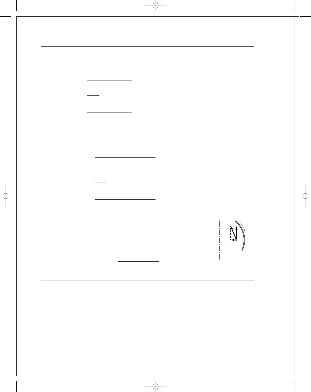
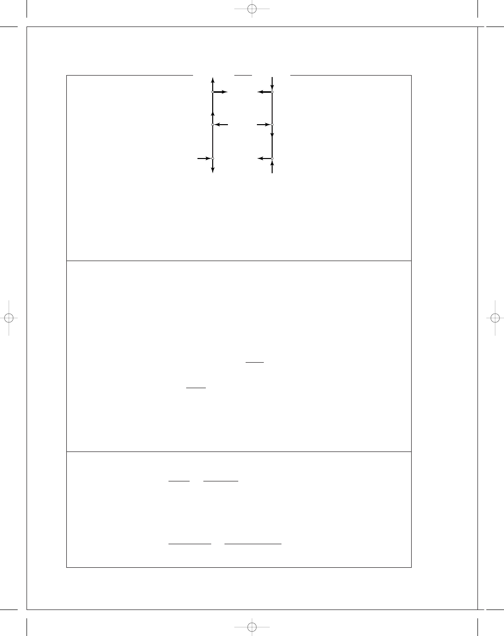
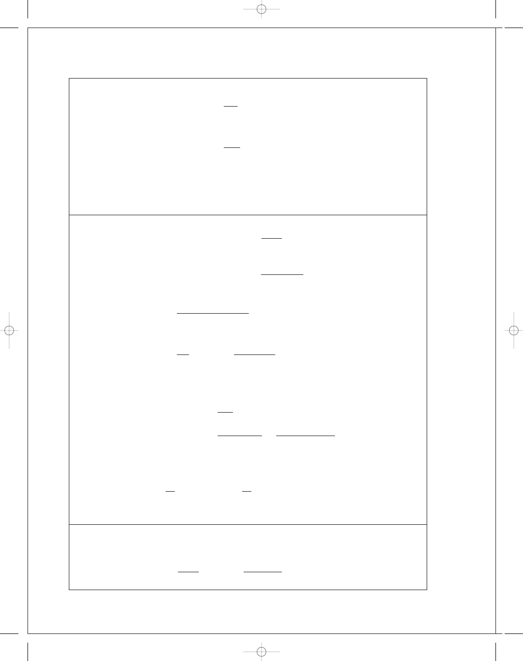
Note from figure that
+y for secondary shoe is opposite to
+y for primary shoe.
Combining horizontal and vertical components,
R
H
= −0.658 − 0.143 = −0.801 kN
R
V
= 9.88 − 4.03 = 5.85 kN
R
=
(0
.801)
2
+ (5.85)
2
= 5.90 kN Ans.
16-5
Preliminaries:
θ
1
= 45° − tan
−
1
(150
/200) = 8.13°, θ
2
= 98.13°
θ
a
= 90°, a = [(150)
2
+ (200)
2
]
1
/
2
= 250 mm
Eq. (16-8):
A
=
1
2
sin
2
θ
98
.
13°
8
.
13°
= 0.480
Let
C
=
θ
2
θ
1
sin
θ dθ = −
cos
θ
98
.
13°
8
.
13°
= 1.1314
y
y
x
x
R
R
V
R
H
budynas_SM_ch16.qxd 12/05/2006 17:45 Page 400
FIRST PAGES
Chapter 16
401
Eq. (16-2):
M
f
=
f p
a
br
sin
θ
a
(r C
− a A) =
0
.25p
a
(0
.030)(0.150)
sin 90°
[0
.15(1.1314) − 0.25(0.48)]
= 5.59(10
−
5
) p
a
N
· m
Eq. (16-8):
B
=
θ
2
−
1
4
sin 2
θ
98
.
13
π/
180 rad
8
.
13
π/
180 rad
= 0.925
Eq. (16-3):
M
N
=
p
a
br a
sin
θ
a
B
=
p
a
(0
.030)(0.150)(0.250)
1
(0
.925)
= 1.0406(10
−
3
) p
a
N
· m
Using F
= (M
N
− M
f
)
/c, we obtain
400
=
104
.06 − 5.59
0
.5(10
5
)
p
a
or
p
a
= 203 kPa Ans.
T
=
f p
a
br
2
C
sin
θ
a
=
0
.25(203)(10
3
)(0
.030)(0.150)
2
1
(1
.1314)
= 38.76 N · m Ans.
16-6
For
+3 ˆσ
f
:
f
= ¯f + 3 ˆσ
f
= 0.25 + 3(0.025) = 0.325
M
f
= 5.59(10
−
5
) p
a
0
.325
0
.25
= 7.267(10
−
5
) p
a
Eq. (16-4):
400
=
104
.06 − 7.267
10
5
(0
.500)
p
a
p
a
= 207 kPa
T
= 38.75
207
203
0
.325
0
.25
= 51.4 N · m Ans.
Similarly, for
−3 ˆσ
f
:
f
= ¯f − 3 ˆσ
f
= 0.25 − 3(0.025) = 0.175
M
f
= 3.913(10
−
5
) p
a
p
a
= 200 kPa
T
= 26.7 N · m Ans.
16-7
Preliminaries:
θ
2
= 180° − 30° − tan
−
1
(3
/12) = 136°, θ
1
= 20° − tan
−
1
(3
/12) = 6°,
θ
a
= 90
◦
,
a
= [(3)
2
+ (12)
2
]
1
/
2
= 12.37 in, r = 10 in,
f
= 0.30, b = 2 in.
Eq. (16-2):
M
f
=
0
.30(150)(2)(10)
sin 90°
136
◦
6°
sin
θ(10 − 12.37 cos θ) dθ
= 12 800 lbf · in
budynas_SM_ch16.qxd 12/05/2006 17:45 Page 401
FIRST PAGES
402
Solutions Manual • Instructor’s Solution Manual to Accompany Mechanical Engineering Design
Eq. (16-3):
M
N
=
150(2)(10)(12
.37)
sin 90°
136°
6°
sin
2
θ dθ = 53 300 lbf · in
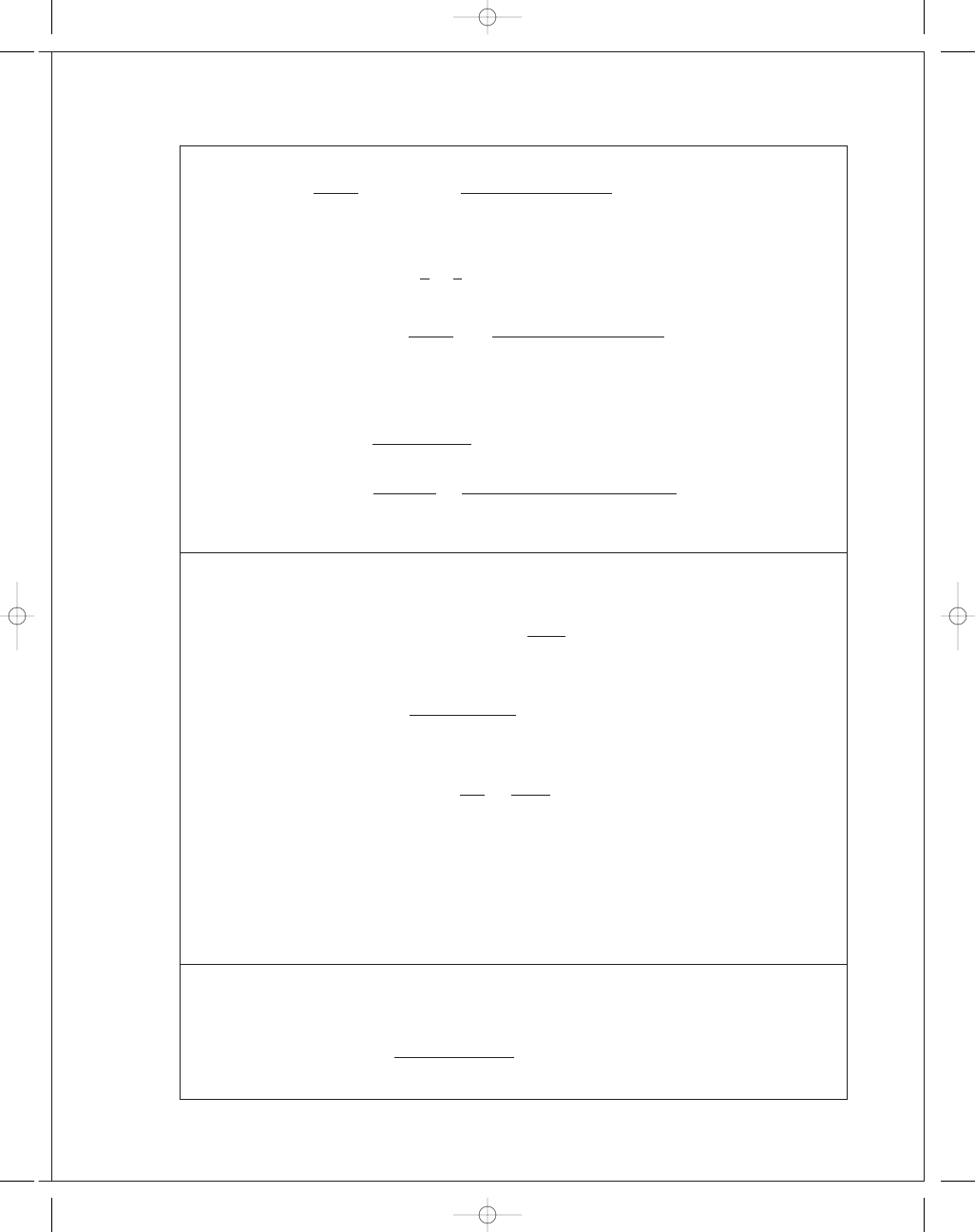
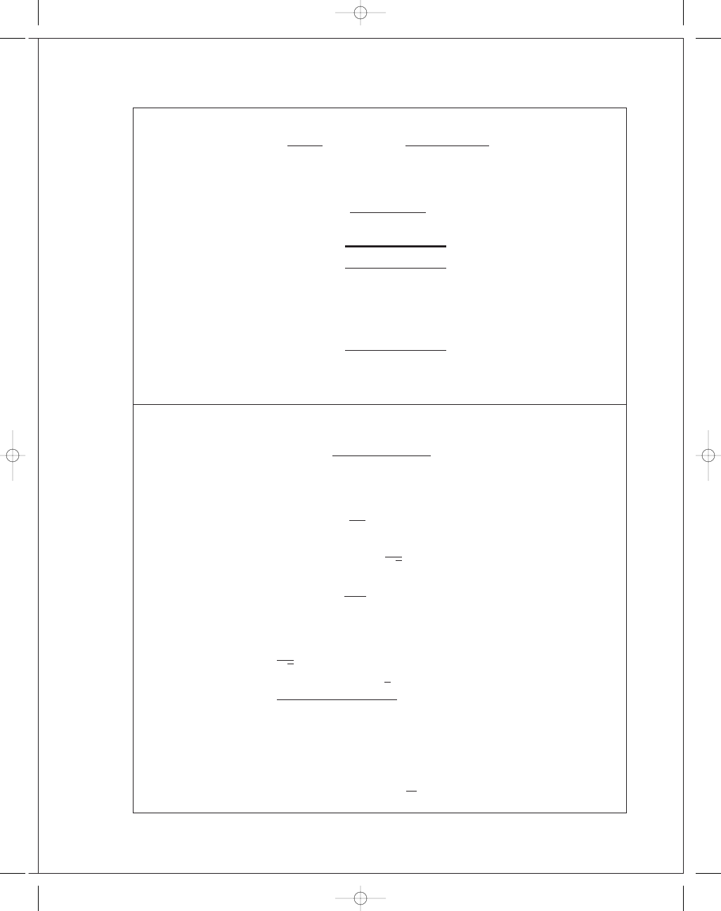
LH shoe:
c
L
= 12 + 12 + 4 = 28 in
Now note that M
f
is cw and M
N
is ccw. Thus,
F
L
=
53 300
− 12 800
28
= 1446 lbf
Eq. (16-6):
T
L
=
0
.30(150)(2)(10)
2
(cos 6°
− cos 136°)
sin 90°
= 15 420 lbf · in
RH shoe:
M
N
= 53 300
p
a
150
= 355.3p
a
,
M
f
= 12 800
p
a
150
= 85.3p
a
On this shoe, both M
N
and M
f
are ccw.
Also
c
R
= (24 − 2 tan 14°) cos 14° = 22.8 in
F
act
= F
L
sin 14°
= 361 lbf Ans.
F
R
= F
L
/ cos 14° = 1491 lbf
Thus
1491
=
355
.3 + 85.3
22
.8
p
a
⇒ p
a
= 77.2 psi
Then
T
R
=
0
.30(77.2)(2)(10)
2
(cos 6°
− cos 136°)
sin 90°
= 7940 lbf · in
T
total
= 15 420 + 7940 = 23 400 lbf · in Ans.
16-8
M
f
= 2
θ
2
0
( f d N )(a
cos
θ − r) where d N = pbr dθ
= 2 f pbr
θ
2
0
(a
cos
θ − r) dθ = 0
From which
a
θ
2
0
cos
θ dθ = r
θ
2
0
d
θ
a
=
r
θ
2
sin
θ
2
=
r (60°)(
π/180)
sin 60°
= 1.209r
Eq. (16-15)
a
=
4r sin 60°
2(60)(
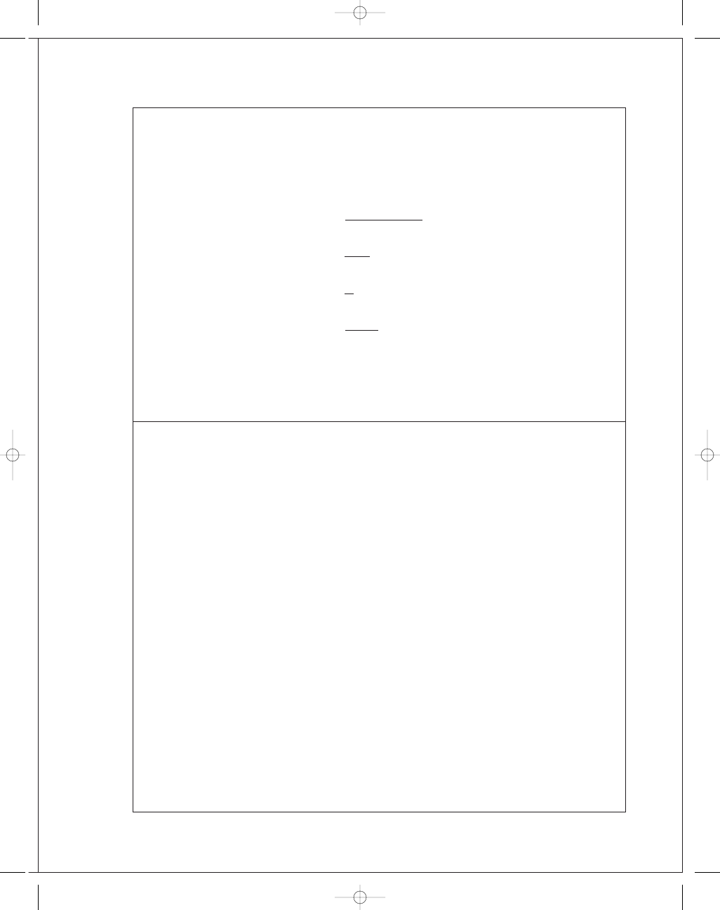
π/180) + sin[2(60)]
= 1.170r
16"
14
⬚
F
L
⫽ 1446 lbf
F
act
⫽ 361 lbf
F
R
⫽ 1491 lbf
4"
budynas_SM_ch16.qxd 12/05/2006 17:45 Page 402
FIRST PAGES
Chapter 16
403
16-9
(a) Counter-clockwise rotation,
θ
2
= π/4 rad, r = 13.5/2 = 6.75 in
a
=
4r sin
θ
2
2
θ
2
+ sin 2θ
2
=
4(6
.75) sin(π/4)
2
π/4 + sin(2π/4)
= 7.426 in
e
= 2(7.426) = 14.85 in Ans.
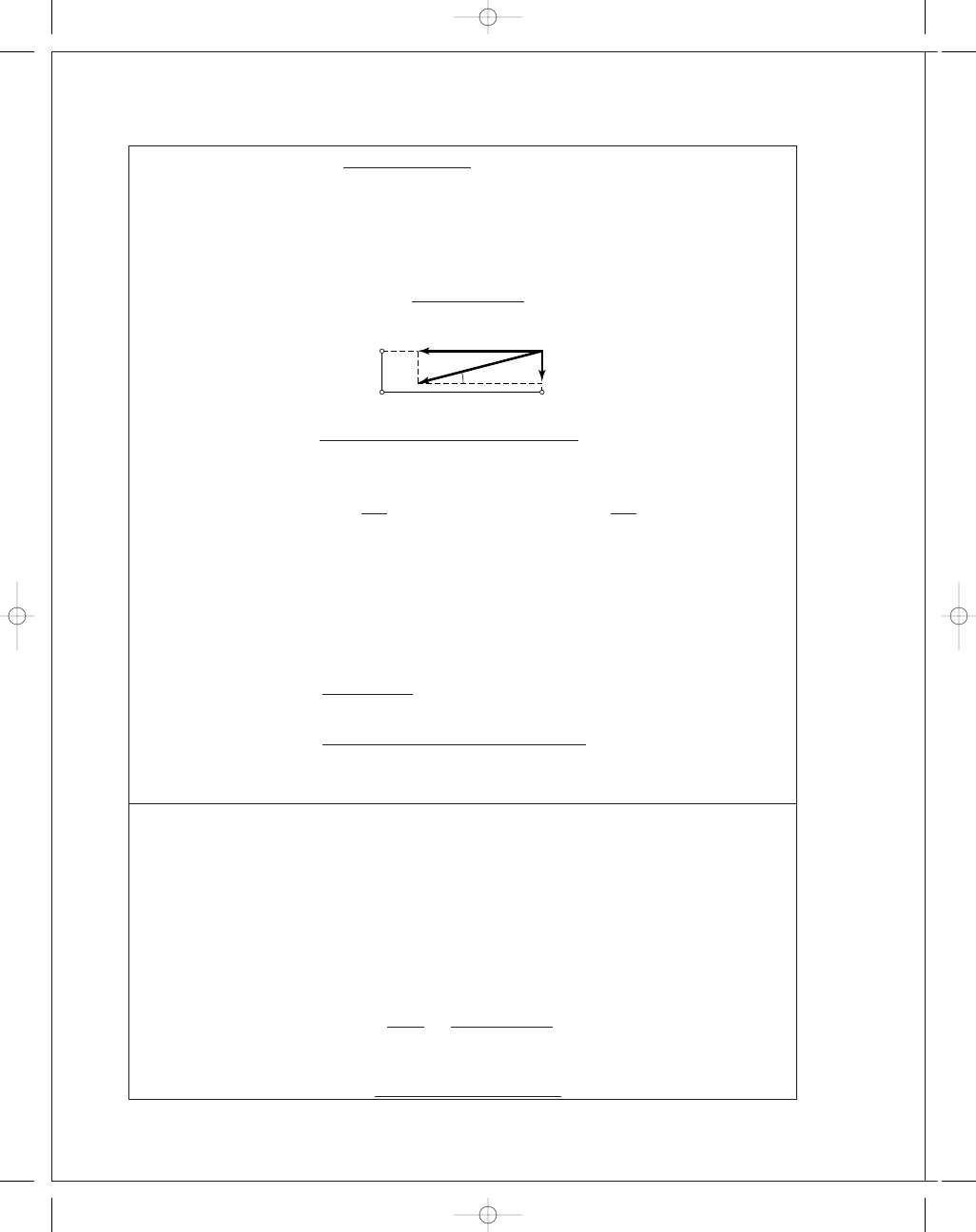
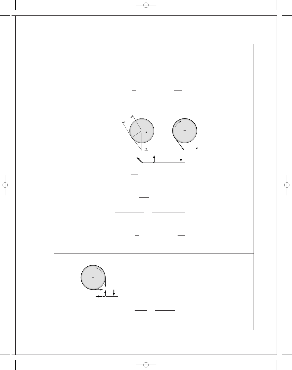
(b)
α = tan
−
1
(3
/14.85) = 11.4°
M
R
= 0 = 3F
x
− 6.375P
F
x
= 2.125P
F
x
= 0 = −F
x
+ R
x
R
x
= F
x
= 2.125P
F
y
= F
x
tan 11
.4
◦
= 0.428P
F
y
= −P − F
y
+ R
y
R
y
= P + 0.428P = 1.428P
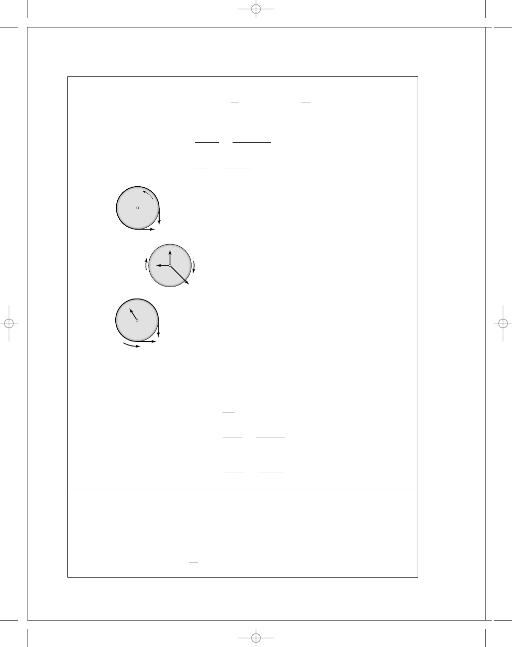
Left shoe lever.
M
R
= 0 = 7.78S
x
− 15.28F
x
S
x
=
15
.28
7
.78
(2
.125P) = 4.174P
S
y
= f S
x
= 0.30(4.174P)
= 1.252P
F
y
= 0 = R
y
+ S
y
+ F
y
R
y
= −F
y
− S
y
= −0.428P − 1.252P
= −1.68P
F
x
= 0 = R
x
− S
x
+ F
x
R
x
= S
x
− F
x
= 4.174P − 2.125P
= 2.049P
R
x
S
x
S
y
R
y
F
x
F
y
7.78"
15.28"
1.428P
2.125P
2.125P
0.428P
P
0.428P
2.125P
tie rod
2.125P
0.428P
␣
6.375"
Actuation
lever
R
x
R
y
F
x
F
y
3"
P
budynas_SM_ch16.qxd 12/05/2006 17:45 Page 403
FIRST PAGES
404
Solutions Manual • Instructor’s Solution Manual to Accompany Mechanical Engineering Design
(c) The direction of brake pulley rotation affects the sense of S
y
, which has no effect on
the brake shoe lever moment and hence, no effect on S
x
or the brake torque.
The brake shoe levers carry identical bending moments but the left lever carries a
tension while the right carries compression (column loading). The right lever is de-
signed and used as a left lever, producing interchangeable levers (identical levers). But
do not infer from these identical loadings.
16-10
r
= 13.5/2 = 6.75 in, b = 7.5 in, θ
2
= 45°
From Table 16-3 for a rigid, molded nonasbestos use a conservative estimate of
p
a
= 100 psi, f = 0.31.
In Eq. (16-16):
2
θ
2
+ sin 2θ
2
= 2(π/4) + sin 2(45°) = 2.571
From Prob. 16-9 solution,
N
= S
x
= 4.174P =
p
a
br
2
(2
.571) = 1.285p
a
br
P
=
1
.285
4
.174
(100)(7
.5)(6.75) = 1560 lbf Ans.
Applying Eq. (16-18) for two shoes,
T
= 2a f N = 2(7.426)(0.31)(4.174)(1560)
= 29 980 lbf · in Ans.
16-11
From Eq. (16-22),
P
1
=
p
a
b D
2
=
90(4)(14)
2
= 2520 lbf Ans.
f
φ = 0.25(π)(270°/180°) = 1.178
Eq. (16-19): P
2
= P
1
exp(
− f φ) = 2520 exp(−1.178) = 776 lbf Ans.
T
=
( P
1
− P
2
) D
2
=
(2520
− 776)14
2
= 12 200 lbf · in Ans.
Ans.
1.252P
2.049P
4.174P
2.68P
Right shoe lever
2.125P
1.428P
2.049P
4.174P
1.252P
1.68P
Left shoe lever
2.125P
0.428P
budynas_SM_ch16.qxd 12/05/2006 17:45 Page 404
FIRST PAGES
Chapter 16
405
16-12
Given: D
= 300 mm,
f
= 0.28, b = 80 mm, φ = 270°,
P
1
= 7600 N.
f
φ = 0.28(π)(270
◦
/180
◦
)
= 1.319
P
2
= P
1
exp(
− f φ) = 7600 exp(−1.319) = 2032 N
p
a
=
2P
1
b D
=
2(7600)
80(300)
= 0.6333 N/mm
2
or
633 kPa
Ans.
T
= (P
1
− P
2
)
D
2
= (7600 − 2032)
300
2
= 835 200 N · mm or 835.2 N · m Ans.
16-13
α = cos
−
1
125
200
= 51.32°
φ = 270° − 51.32° = 218.7°
f
φ = 0.30(218.7)
π
180°
= 1.145
P
2
=
(125
+ 275)F
125
=
(125
+ 275)400
125
= 1280 N Ans.
P
1
= P
2
exp( f
φ) = 1280 exp(1.145) = 4022 N
T
= (P
1
− P
2
)
D
2
= (4022 − 1280)
250
2
= 342 750 N · mm or 343 N · m Ans.
16-14
(a)
Eq. (16-22):
P
1
=
p
a
b D
2
=
70(3)(16)
2
= 1680 lbf
f
φ = 0.20(3π/2) = 0.942
D
= 16
"
,
b
= 3
"
n
= 200 rev/min
f
= 0.20,
p
a
= 70 psi
P
1
P
2
P
1
P
2
P
P
1
P
2
␣
F
200
125
275
P
2
P
1
125
budynas_SM_ch16.qxd 12/05/2006 17:45 Page 405
FIRST PAGES
406
Solutions Manual • Instructor’s Solution Manual to Accompany Mechanical Engineering Design
Eq. (16-14):
P
2
= P
1
exp(
− f φ) = 1680 exp(−0.942) = 655 lbf
T
= (P
1
− P
2
)
D
2
= (1680 − 655)
16
2
= 8200 lbf · in Ans.
H
=
T n
63 025
=
8200(200)
63 025
= 26.0 hp Ans.
P
=
3P
1
10
=
3(1680)
10
= 504 lbf Ans.
(b)
The radial load on the bearing pair is 1803 lbf. If the bearing is straddle mounted with
the drum at center span, the bearing radial load is 1803
/2 = 901 lbf.
(c) Eq. (16-22):
p
=
2P
b D
p
|
θ=
0°
=
2P
1
3(16)
=
2(1680)
3(16)
= 70 psi Ans.
As it should be
p
|
θ=
270°
=
2P
2
3(16)
=
2(655)
3(16)
= 27.3 psi Ans.
16-15
Given:
φ =270°, b=2.125 in, f =0.20, T =150 lbf · ft, D =8.25 in, c
2
= 2.25 in
Notice that the pivoting rocker is not located on the vertical centerline of the drum.
(a) To have the band tighten for ccw rotation, it is necessary to have c
1
< c
2
. When fric-
tion is fully developed,
P
1
P
2
= exp( f φ) = exp[0.2(3π/2)] = 2.566
Net torque on drum due to brake band:
T
= T
P
1
− T
P
2
= 13 440 − 5240
= 8200 lbf · in
1803 lbf
8200 lbf
•
in
1680 lbf
655 lbf
Force of shaft on the drum: 1680 and 655 lbf
T
P
1
= 1680(8) = 13 440 lbf · in
T
P
2
= 655(8) = 5240 lbf · in
1680 lbf
1803 lbf
655 lbf
13,440 lbf
•
in
5240 lbf
•
in
Force of belt on the drum:
R
= (1680
2
+ 655
2
)
1
/
2
= 1803 lbf
1680 lbf
655 lbf
budynas_SM_ch16.qxd 12/05/2006 17:45 Page 406
FIRST PAGES
Chapter 16
407
If friction is not fully developed
P
1
/P
2
≤ exp( f φ)
To help visualize what is going on let’s add a force W parallel to P
1
, at a lever arm of
c
3
. Now sum moments about the rocker pivot.
M
= 0 = c
3
W
+ c
1
P
1
− c
2
P
2
From which
W
=
c
2
P
2
− c
1
P
1
c
3
The device is self locking for ccw rotation if W is no longer needed, that is, W
≤ 0.
It follows from the equation above
P
1
P
2
≥
c
2
c
1
When friction is fully developed
2
.566 = 2.25/c
1
c
1
=
2
.25
2
.566
= 0.877 in
When P
1
/P
2
is less than 2.566, friction is not fully developed. Suppose P
1
/P
2
= 2.25,
then
c
1
=
2
.25
2
.25
= 1 in
We don’t want to be at the point of slip, and we need the band to tighten.
c
2
P
1
/P
2
≤ c
1
≤ c
2
When the developed friction is very small, P
1
/P
2
→ 1 and c
1
→ c
2
Ans
.
(b) Rocker has c
1
= 1 in
P
1
P
2
=
c
2
c
1
=
2
.25
1
= 2.25
f
=
ln( P
1
/P
2
)
φ
=
ln 2
.25
3
π/2
= 0.172
Friction is not fully developed, no slip.
T
= (P
1
− P
2
)
D
2
= P
2
P
1
P
2
− 1
D
2
Solve for P
2
P
2
=
2T
[( P
1
/P
2
)
− 1]D
=
2(150)(12)
(2
.25 − 1)(8.25)
= 349 lbf
P
1
= 2.25P
2
= 2.25(349) = 785 lbf
p
=
2P
1
b D
=
2(785)
2
.125(8.25)
= 89.6 psi Ans.
budynas_SM_ch16.qxd 12/05/2006 17:45 Page 407
FIRST PAGES
408
Solutions Manual • Instructor’s Solution Manual to Accompany Mechanical Engineering Design
(c) The torque ratio is 150(12)
/100 or 18-fold.
P
2
=
349
18
= 19.4 lbf
P
1
= 2.25P
2
= 2.25(19.4) = 43.6 lbf
p
=
89
.6
18
= 4.98 psi Ans.
Comment:
As the torque opposed by the locked brake increases, P
2
and P
1
increase (although
ratio is still 2.25), then p follows. The brake can self-destruct. Protection could be
provided by a shear key.
16-16
(a) From Eq. (16-23), since
F
=
πp
a
d
2
( D
− d)
then
p
a
=
2F
πd(D − d)
and it follows that
p
a
=
2(5000)
π(225)(300 − 225)
= 0.189 N/mm
2
or
189 000 N/m
2
or
189 kPa
Ans
.
T
=
F f
4
( D
+ d) =
5000(0
.25)
4
(300
+ 225)
= 164 043 N · mm or 164 N · m Ans.
(b) From Eq. (16-26),
F
=
πp
a
4
( D
2
− d
2
)
p
a
=
4F
π(D
2
− d
2
)
=
4(5000)
π(300
2
− 225
2
)
= 0.162 N/mm
2
= 162 kPa Ans.
From Eq. (16-27),
T
=
π
12
f p
a
( D
3
− d
3
)
=
π
12
(0
.25)(162)(10
3
)(300
3
− 225
3
)(10
−
3
)
3
= 166 N · m Ans.
16-17
(a) Eq. (16-23):
F
=
πp
a
d
2
( D
− d) =
π(120)(4)
2
(6
.5 − 4) = 1885 lbf Ans.
budynas_SM_ch16.qxd 12/05/2006 17:45 Page 408
FIRST PAGES
Chapter 16
409
Eq. (16-24):
T
=
π f p
a
d
8
( D
2
− d
2
) N
=
π(0.24)(120)(4)
8
(6
.5
2
− 4
2
)(6)
= 7125 lbf · in Ans.
(b)
T
=
π(0.24)(120d)
8
(6
.5
2
− d
2
)(6)
d, in
T , lbf
· in
2
5191
3
6769
4
7125
Ans.
5
5853
6
2545
(c) The torque-diameter curve exhibits a stationary point maximum in the range of
diameter d. The clutch has nearly optimal proportions.
16-18
(a)
T
=
π f p
a
d( D
2
− d
2
) N
8
= C D
2
d
− Cd
3
Differentiating with respect to d and equating to zero gives
d T
dd
= C D
2
− 3Cd
2
= 0
d*
=
D
√
3
Ans.
d
2
T
dd
2
= −6 Cd
which is negative for all positive d. We have a stationary point maximum.
(b)
d*
=
6
.5
√
3
= 3.75 in Ans.
T *
=
π(0.24)(120)
6
.5/
√
3
8
[6
.5
2
− (6.5
2
/3)](6) = 7173 lbf · in
(c) The table indicates a maximum within the range:
3
≤ d ≤ 5 in
(d) Consider:
0
.45 ≤
d
D
≤ 0.80
budynas_SM_ch16.qxd 12/05/2006 17:45 Page 409
FIRST PAGES
410
Solutions Manual • Instructor’s Solution Manual to Accompany Mechanical Engineering Design
Multiply through by D
0
.45D ≤ d ≤ 0.80D
0
.45(6.5) ≤ d ≤ 0.80(6.5)
2
.925 ≤ d ≤ 5.2 in
d
D
∗
= d
∗
/D =
1
√
3
= 0.577
which lies within the common range of clutches.
Yes.
Ans.
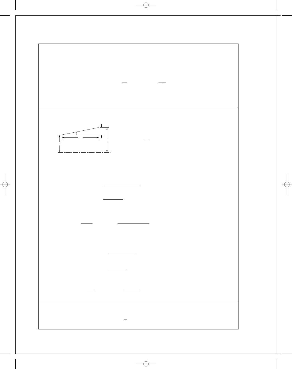
16-19
Given: d
= 0.306 m, l = 0.060 m, T = 0.200 kN · m, D = 0.330 m, f = 0.26.
α = tan
−
1
12
60
= 11.31°
Uniform wear
Eq. (16-45):
0
.200 =
π(0.26)(0.306) p
a
8 sin 11
.31°
(0
.330
2
− 0.306
2
)
= 0.002 432p
a
p
a
=
0
.200
0
.002 432
= 82.2 kPa Ans.
Eq. (16-44):
F
=
πp
a
d
2
( D
− d) =
π(82.2)(0.306)
2
(0
.330 − 0.306) = 0.949 kN Ans.
Uniform pressure
Eq. (16-48):
0
.200 =
π(0.26) p
a
12 sin 11
.31°
(0
.330
3
− 0.306
3
)
= 0.002 53p
a
p
a
=
0
.200
0
.002 53
= 79.1 kPa Ans.
Eq. (16-47):
F
=
πp
a
4
( D
2
− d
2
)
=
π(79.1)
4
(0
.330
2
− 0.306
2
)
= 0.948 kN Ans.
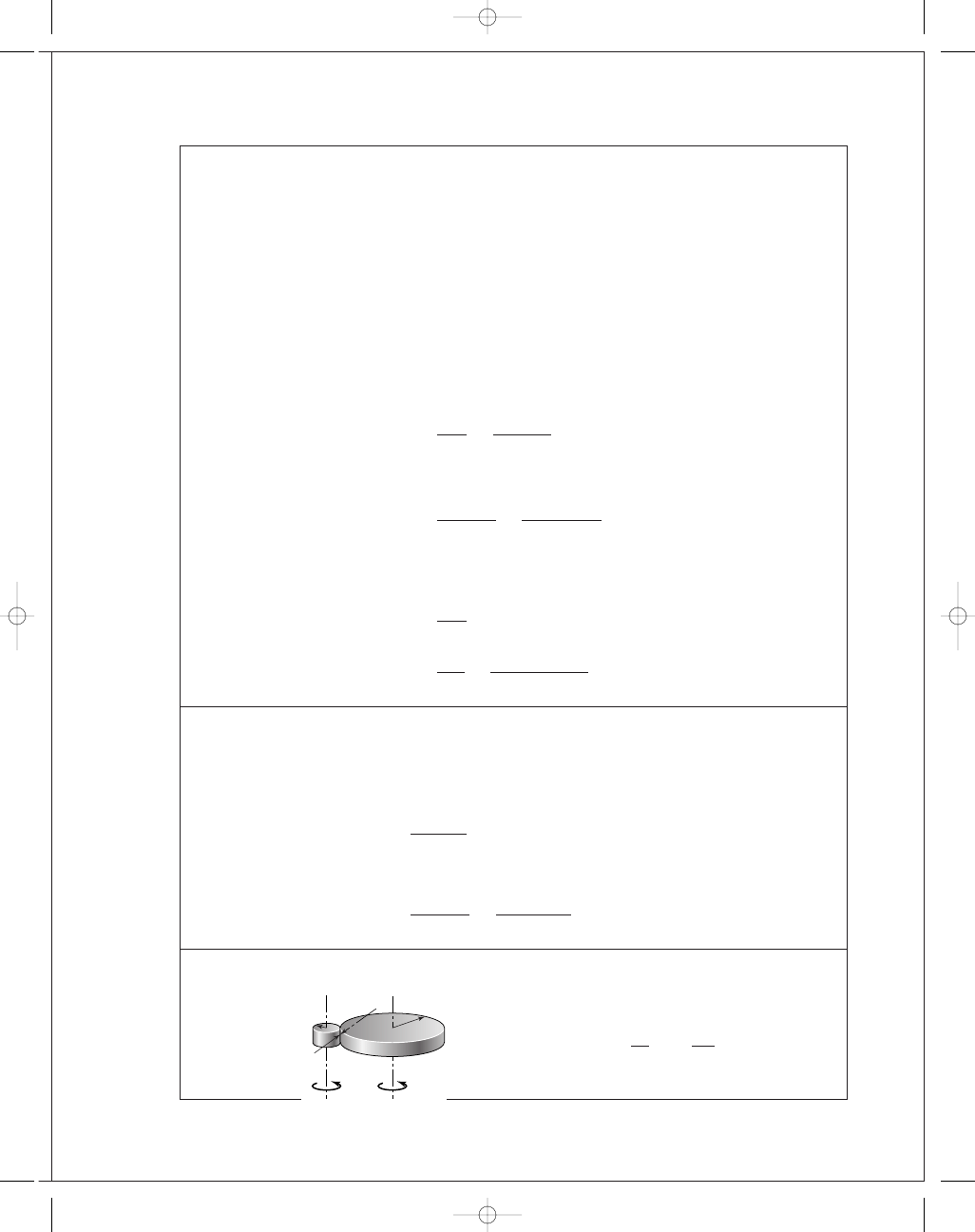
16-20
Uniform wear
Eq. (16-34):
T
=
1
2
(
θ
2
− θ
1
) f p
a
r
i
r
2
o
− r
2
i
165
153
12
60
Not to scale
␣
CL
budynas_SM_ch16.qxd 12/05/2006 17:45 Page 410

FIRST PAGES
Chapter 16
411
Eq. (16-33):
F
= (θ
2
− θ
1
) p
a
r
i
(r
o
− r
i
)
Thus,
T
f F D
=
(1
/2)(θ
2
− θ
1
) f p
a
r
i
r
2
o
− r
2
i
f (
θ
2
− θ
1
) p
a
r
i
(r
o
− r
i
)( D)
=
r
o
+ r
i
2D
=
D
/2 + d/2
2D
=
1
4
1
+
d
D
O.K.
Ans.
Uniform pressure
Eq. (16-38):
T
=
1
3
(
θ
2
− θ
1
) f p
a
r
3
o
− r
3
i
Eq. (16-37):
F
=
1
2
(
θ
2
− θ
1
) p
a
r
2
o
− r
2
i
T
f F D
=
(1
/3)(θ
2
− θ
1
) f p
a
r
3
o
− r
3
i
(1
/2) f (θ
2
− θ
1
) p
a
r
2
o
− r
2
i
D
=
2
3
( D
/2)
3
− (d/2)
3
[( D
/2)
2
− (d/2)
2
D]
=
2( D
/2)
3
(1
− (d/D)
3
)
3( D
/2)
2
[1
− (d/D)
2
]D
=
1
3
1
− (d/D)
3
1
− (d/D)
2
O
.K. Ans.
16-21
ω = 2πn/60 = 2π 500/60 = 52.4 rad/s
T
=
H
ω
=
2(10
3
)
52
.4
= 38.2 N · m
Key:
F
=
T
r
=
38
.2
12
= 3.18 kN
Average shear stress in key is
τ =
3
.18(10
3
)
6(40)
= 13.2 MPa Ans.
Average bearing stress is
σ
b
= −
F
A
b
= −
3
.18(10
3
)
3(40)
= −26.5 MPa Ans.
Let one jaw carry the entire load.
r
a
v
=
1
2
26
2
+
45
2
= 17.75 mm
F
=
T
r
a
v
=
38
.2
17
.75
= 2.15 kN
budynas_SM_ch16.qxd 12/05/2006 17:45 Page 411
FIRST PAGES
412
Solutions Manual • Instructor’s Solution Manual to Accompany Mechanical Engineering Design
The bearing and shear stress estimates are
σ
b
=
−2.15(10
3
)
10(22
.5 − 13)
= −22.6 MPa Ans.
τ =
2
.15(10
3
)
10[0
.25π(17.75)
2
]
= 0.869 MPa Ans.
16-22
ω
1
= 2πn/60 = 2π(1800)/60 = 188.5 rad/s
ω
2
= 0
From Eq. (16-51),
I
1
I
2
I
1
+ I
2
=
T t
1
ω
1
− ω
2
=
320(8
.3)
188
.5 − 0
= 14.09 N · m · s
2
Eq. (16-52):
E
= 14.09
188
.5
2
2
(10
−
3
)
= 250 kJ
Eq. (16-55):
T =
E
C
p
m
=
250(10
3
)
500(18)
= 27.8
◦
C
Ans.
16-23
n
=
n
1
+ n
2
2
=
260
+ 240
2
= 250 rev/min
C
s
=
260
− 240
250
= 0.08 Ans.
ω = 2π(250)/60 = 26.18 rad/s
I
=
E
2
− E
1
C
s
ω
2
=
5000(12)
0
.08(26.18)
2
= 1094 lbf · in · s
2
I
x
=
m
8
d
2
o
+ d
2
i
=
W
8g
d
2
o
+ d
2
i
W
=
8g I
d
2
o
+ d
2
i
=
8(386)(1094)
60
2
+ 56
2
= 502 lbf
w = 0.260 lbf/in
3
for cast iron
V
=
W
w
=
502
0
.260
= 1931 in
3
Also,
V
=
πt
4
d
2
o
− d
2
i
=
πt
4
60
2
− 56
2
= 364t in
3
Equating the expressions for volume and solving for t,
t
=
1931
364
= 5.3 in Ans.
budynas_SM_ch16.qxd 12/05/2006 17:45 Page 412
FIRST PAGES
Chapter 16
413
16-24
(a) The useful work performed in one revolution of the crank shaft is
U
= 35(2000)(8)(0.15) = 84(10
3
) in
· lbf
Accounting for friction, the total work done in one revolution is
U
= 84(10
3
)
/(1 − 0.16) = 100(10
3
) in
· lbf
Since 15% of the crank shaft stroke is 7.5% of a crank shaft revolution, the energy
fluctuation is
E
2
− E
1
= 84(10
3
)
− 100(10
3
)(0
.075) = 76.5(10
3
) in
· lbf Ans.
(b) For the flywheel
n
= 6(90) = 540 rev/min
ω =
2
πn
60
=
2
π(540)
60
= 56.5 rad/s
Since
C
s
= 0.10
I
=
E
2
− E
1
C
s
ω
2
=
76
.5(10
3
)
0
.10(56.5)
2
= 239.6 lbf · in · s
2
Assuming all the mass is concentrated at the effective diameter, d,
I
=
md
2
4
W
=
4g I
d
2
=
4(386)(239
.6)
48
2
= 161 lbf Ans.
16-25
Use Ex. 16-6 and Table 16-6 data for one cylinder of a 3-cylinder engine.
C
s
= 0.30
n
= 2400 rev/min or 251 rad/s
T
m
=
3(3368)
4
π
= 804 in · lbf Ans.
E
2
− E
1
= 3(3531) = 10 590 in · lbf
I
=
E
2
− E
1
C
s
ω
2
=
10 590
0
.30(251
2
)
= 0.560 in · lbf · s
2
Ans
.
16-26
(a)
(1)
(T
2
)
1
= −F
21
r
P
= −
T
2
r
G
r
P
=
T
2
−n
Ans
.
r
P
r
G
T
1
F
12
F
21
T
2
budynas_SM_ch16.qxd 12/05/2006 17:45 Page 413
FIRST PAGES
414
Solutions Manual • Instructor’s Solution Manual to Accompany Mechanical Engineering Design
(2)
Equivalent energy
(1
/2)I
2
ω
2
2
= (1/2)(I
2
)
1
w
2
1
( I
2
)
1
=
ω
2
2
ω
2
1
I
2
=
I
2
n
2
Ans.
(3)
I
G
I
P
=
r
G
r
P
2
m
G
m
P
=
r
G
r
P
2
r
G
r
P
2
= n
4
From (2)
( I
2
)
1
=
I
G
n
2
=
n
4
I
P
n
2
= n
2
I
P
Ans.
(b) I
e
= I
M
+ I
P
+ n
2
I
P
+
I
L
n
2
Ans.
(c) I
e
= 10 + 1 + 10
2
(1)
+
100
10
2
= 10 + 1 + 100 + 1 = 112
reflected load inertia
reflected gear inertia
Ans.
pinion inertia
armature inertia
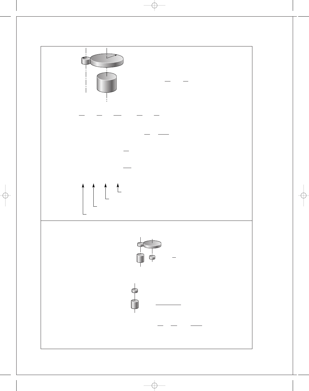
16-27
(a) Reflect I
L
, I
G
2
to the center shaft
Reflect the center shaft to the motor shaft
I
e
= I
M
+ I
P
+ n
2
I
P
+
I
P
n
2
+
m
2
n
2
I
P
+
I
L
m
2
n
2
Ans
.
I
P
I
M
⫹ n
2
I
P
⫹
I
P
⫹ m
2
I
P
⫹ I
L
兾m
2
n
2
I
P
I
G1
I
M
n
I
P
⫹ m
2
I
P
⫹
I
L
m
2
r
P
r
G
I
L
budynas_SM_ch16.qxd 12/05/2006 17:45 Page 414
FIRST PAGES
Chapter 16
415
(b) For R
= constant = nm, I
e
= I
M
+ I
P
+ n
2
I
P
+
I
P
n
2
+
R
2
I
P
n
4
+
I
L
R
2
Ans.
(c) For R
= 10,
∂ I
e
∂n
= 0 + 0 + 2n(1) −
2(1)
n
3
−
4(10
2
)(1)
n
5
+ 0 = 0
n
6
− n
2
− 200 = 0
From which
n*
= 2.430 Ans.
m*
=
10
2
.430
= 4.115 Ans.
Notice that n*and m* are independent of I
L
.
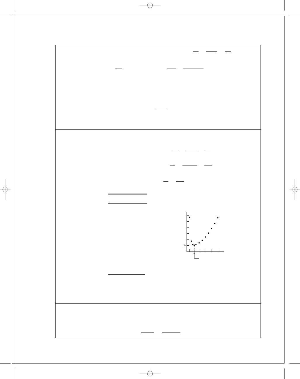
16-28
From Prob. 16-27,
I
e
= I
M
+ I
P
+ n
2
I
P
+
I
P
n
2
+
R
2
I
P
n
4
+
I
L
R
2
= 10 + 1 + n
2
(1)
+
1
n
2
+
100(1)
n
4
+
100
10
2
= 10 + 1 + n
2
+
1
n
2
+
100
n
4
+ 1
n
I
e
1.00
114.00
1.50
34.40
2.00
22.50
2.43
20.90
3.00
22.30
4.00
28.50
5.00
37.20
6.00
48.10
7.00
61.10
8.00
76.00
9.00
93.00
10.00
112.02
Optimizing the partitioning of a double reduction lowered the gear-train inertia to
20
.9/112 = 0.187, or to 19% of that of a single reduction. This includes the two addi-
tional gears.
16-29
Figure 16-29 applies,
t
2
= 10 s, t
1
= 0.5 s
t
2
− t
1
t
1
=
10
− 0.5
0
.5
= 19
I
e
n
0 1 2
2.43
4
6
8
10
100
20.9
budynas_SM_ch16.qxd 12/05/2006 17:45 Page 415

FIRST PAGES
416
Solutions Manual • Instructor’s Solution Manual to Accompany Mechanical Engineering Design
The load torque, as seen by the motor shaft (Rule 1, Prob. 16-26), is
T
L
=
1300(12)
10
= 1560 lbf · in
The rated motor torque T
r
is
T
r
=
63 025(3)
1125
= 168.07 lbf · in
For Eqs. (16-65):
ω
r
=
2
π
60
(1125)
= 117.81 rad/s
ω
s
=
2
π
60
(1200)
= 125.66 rad/s
a
=
−T
r
ω
s
− ω
r
= −
168
.07
125
.66 − 117.81
= −21.41
b
=
T
r
ω
s
ω
s
− ω
r
=
168
.07(125.66)
125
.66 − 117.81
= 2690.4 lbf · in
The linear portion of the squirrel-cage motor characteristic can now be expressed as
T
M
= −21.41ω + 2690.4 lbf · in
Eq. (16-68):
T
2
= 168.07
1560
− 168.07
1560
− T
2
19
One root is 168.07 which is for infinite time. The root for 10 s is wanted. Use a successive
substitution method
T
2
New T
2
0.00
19.30
19.30
24.40
24.40
26.00
26.00
26.50
26.50
26.67
Continue until convergence.
T
2
= 26.771
Eq. (16-69):
I
=
−21.41(10 − 0.5)
ln(26
.771/168.07)
= 110.72 in · lbf · s/rad
ω =
T
− b
a
budynas_SM_ch16.qxd 12/05/2006 17:45 Page 416

FIRST PAGES
Chapter 16
417
ω
max
=
T
2
− b
a
=
26
.771 − 2690.4
−21.41
= 124.41 rad/s Ans.
ω
min
= 117.81 rad/s Ans.
¯ω =
124
.41 + 117.81
2
= 121.11 rad/s
C
s
=
ω
max
− ω
min
(
ω
max
+ ω
min
)
/2
=
124
.41 − 117.81
(124
.41 + 117.81)/2
= 0.0545 Ans.
E
1
=
1
2
I
ω
2
r
=
1
2
(110
.72)(117.81)
2
= 768 352 in · lbf
E
2
=
1
2
I
ω
2
2
=
1
2
(110
.72)(124.41)
2
= 856 854 in · lbf
E = E
1
− E
2
= 768 352 − 856 854 = −88 502 in · lbf
Eq. (16-64):
E = C
s
I
¯ω
2
= 0.0545(110.72)(121.11)
2
= 88 508 in · lbf, close enough Ans.
During the punch
T
=
63 025H
n
H
=
T
L
¯ω(60/2π)
63 025
=
1560(121
.11)(60/2π)
63 025
= 28.6 hp
The gear train has to be sized for 28.6 hp under shock conditions since the flywheel is on
the motor shaft. From Table A-18,
I
=
m
8
d
2
o
+ d
2
i
=
W
8g
d
2
o
+ d
2
i
W
=
8g I
d
2
o
+ d
2
i
=
8(386)(110
.72)
d
2
o
+ d
2
i
If a mean diameter of the flywheel rim of 30 in is acceptable, try a rim thickness of 4 in
d
i
= 30 − (4/2) = 28 in
d
o
= 30 + (4/2) = 32 in
W
=
8(386)(110
.72)
32
2
+ 28
2
= 189.1 lbf
Rim volume V is given by
V
=
πl
4
d
2
o
− d
2
i
=
πl
4
(32
2
− 28
2
)
= 188.5l
budynas_SM_ch16.qxd 12/05/2006 17:45 Page 417
FIRST PAGES
418
Solutions Manual • Instructor’s Solution Manual to Accompany Mechanical Engineering Design
where l is the rim width as shown in Table A-18. The specific weight of cast iron is
γ = 0.260 lbf · in
3
, therefore the volume of cast iron is
V
=
W
γ
=
189
.1
0
.260
= 727.3 in
3
Thus
188
.5 l = 727.3
l
=
727
.3
188
.5
= 3.86 in wide
Proportions can be varied.
16-30
Prob. 16-29 solution has I for the motor shaft flywheel as
I
= 110.72 in · lbf · s
2
/rad
A flywheel located on the crank shaft needs an inertia of 10
2
I (Prob. 16-26, rule 2)
I
= 10
2
(110
.72) = 11 072 in · lbf · s
2
/rad
A 100-fold inertia increase. On the other hand, the gear train has to transmit 3 hp under
shock conditions.
Stating the problem is most of the solution. Satisfy yourself that on the crankshaft:
T
L
= 1300(12) = 15 600 lbf · in
T
r
= 10(168.07) = 1680.7 lbf · in
ω
r
= 117.81/10 = 11.781 rad/s
ω
s
= 125.66/10 = 12.566 rad/s
a
= −21.41(100) = −2141
b
= 2690.35(10) = 26903.5
T
M
= −2141ω
c
+ 26 903.5 lbf · in
T
2
= 1680.6
15 600
− 1680.5
15 600
− T
2
19
The root is 10(26
.67) = 266.7 lbf · in
¯ω = 121.11/10 = 12.111 rad/s
C
s
= 0.0549 (same)
ω
max
= 121.11/10 = 12.111 rad/s Ans.
ω
min
= 117.81/10 = 11.781 rad/s Ans.
E
1
, E
2
,
E and peak power are the same.
From Table A-18
W
=
8g I
d
2
o
+ d
2
i
=
8(386)(11 072)
d
2
o
+ d
2
i
budynas_SM_ch16.qxd 12/05/2006 17:45 Page 418
FIRST PAGES
Chapter 16
419
Scaling will affect d
o
and d
i
, but the gear ratio changed I. Scale up the flywheel in the
Prob. 16-29 solution by a factor of 2.5. Thickness becomes 4(2
.5) = 10 in.
¯d = 30(2.5) = 75 in
d
o
= 75 + (10/2) = 80 in
d
i
= 75 − (10/2) = 70 in
W
=
8(386)(11 072)
80
2
+ 70
2
= 3026 lbf
v =
3026
0
.26
= 11 638 in
3
V
=
π
4
l(80
2
− 70
2
)
= 1178 l
l
=
11 638
1178
= 9.88 in
Proportions can be varied. The weight has increased 3026
/189.1 or about 16-fold while
the moment of inertia I increased 100-fold. The gear train transmits a steady 3 hp. But the
motor armature has its inertia magnified 100-fold, and during the punch there are decel-
eration stresses in the train. With no motor armature information, we cannot comment.
16-31
This can be the basis for a class discussion.
budynas_SM_ch16.qxd 12/05/2006 17:45 Page 419
Wyszukiwarka
Podobne podstrony:
budynas SM ch01
budynas SM ch15
budynas SM ch14
budynas SM ch05
budynas SM ch12
budynas SM ch20
budynas SM ch09
budynas SM ch03
budynas SM ch10
budynas SM ch08
budynas SM ch11
budynas SM ch07
budynas SM ch04
budynas SM ch13
budynas SM ch02
budynas SM ch17
budynas SM ch06
więcej podobnych podstron