FIRST PAGES
Chapter 17
17-1
Given: F-1 Polyamide, b
= 6 in, d = 2 in @ 1750 rev/min
C
= 9(12) = 108 in, vel. ratio 0.5, H
nom
= 2 hp, K
s
= 1.25, n
d
= 1
Table 17-2:
t
= 0.05 in, d
min
= 1.0 in, F
a
= 35 lbf/in,
γ = 0.035 lbf/in
3
, f
= 0.5
Table 17-4:
C
p
= 0.70
w = 12γ bt = 12(0.035)(6)(0.05) = 0.126 lbf/ft
θ
d
= 3.123 rad, exp( f θ) = 4.766 (perhaps)
V
=
πdn
12
=
π(2)(1750)
12
= 916.3 ft/min
(a) Eq. (e), p. 865:
F
c
=
w
32
.17
V
60
2
=
0
.126
32
.17
916
.3
60
2
= 0.913 lbf Ans.
T
=
63 025H
nom
K
s
n
d
n
=
63 025(2)(1
.25)(1)
1750
= 90.0 lbf · in
F =
2T
d
=
2(90)
2
= 90 lbf
Eq. (17-12): ( F
1
)
a
= bF
a
C
p
C
v
= 6(35)(0.70)(1) = 147 lbf Ans.
F
2
= F
1
a
− F = 147 − 90 = 57 lbf Ans.
Do not use Eq. (17-9) because we do not yet know f
.
Eq. (i), p. 866:
F
i
=
F
1
a
+ F
2
2
− F
c
=
147
+ 57
2
− 0.913 = 101.1 lbf Ans.
Eq. (17-7):
f
=
1
θ
d
ln
( F
1
)
a
− F
c
F
2
− F
c
=
1
3
.123
ln
147
− 0.913
57
− 0.913
= 0.307
The friction is thus undeveloped.
(b) The transmitted horsepower is,
H
=
(
F)V
33 000
=
90(916
.3)
33 000
= 2.5 hp Ans.
n
f s
=
H
H
nom
K
s
=
2
.5
2(1
.25)
= 1
From Eq. (17-2),
L
= 225.3 in Ans.
(c) From Eq. (17-13),
dip
=
3C
2
w
2F
i
where C is the center-to-center distance in feet.
dip
=
3(108
/12)
2
(0
.126)
2(101
.1)
= 0.151 in Ans.
budynas_SM_ch17.qxd 12/06/2006 17:29 Page 420
FIRST PAGES
Chapter 17
421
Comment: The friction is under-developed. Narrowing the belt width to 5 in (if size is
available) will increase f
. The limit of narrowing is b
min
= 4.680 in, whence
w = 0.0983 lbf/ft
( F
1
)
a
= 114.7 lbf
F
c
= 0.712 lbf
F
2
= 24.6 lbf
T
= 90 lbf · in (same)
f
= f = 0.50
F = (F
1
)
a
− F
2
= 90 lbf
dip
= 0.173 in
F
i
= 68.9 lbf
Longer life can be obtained with a 6-inch wide belt by reducing F
i
to attain f
= 0.50.
Prob. 17-8 develops an equation we can use here
F
i
=
(
F + F
c
) exp( f
θ) − F
c
exp( f
θ) − 1
F
2
= F
1
− F
F
i
=
F
1
+ F
2
2
− F
c
f
=
1
θ
d
ln
F
1
− F
c
F
2
− F
c
dip
=
3(C D
/12)
2
w
2F
i
which in this case gives
F
1
= 114.9 lbf
F
c
= 0.913 lbf
F
2
= 24.8 lbf
f
= 0.50
F
i
= 68.9 lbf
dip
= 0.222 in
So, reducing F
i
from 101.1 lbf to 68.9 lbf will bring the undeveloped friction up to
0.50, with a corresponding dip of 0.222 in. Having reduced F
1
and F
2
, the endurance
of the belt is improved. Power, service factor and design factor have remained in tack.
17-2
There are practical limitations on doubling the iconic scale. We can double pulley diame-
ters and the center-to-center distance. With the belt we could:
• Use the same A-3 belt and double its width;
• Change the belt to A-5 which has a thickness 0.25 in rather than 2(0
.13) = 0.26 in, and
an increased F
a
;
• Double the thickness and double tabulated F
a
which is based on table thickness.
The object of the problem is to reveal where the non-proportionalities occur and the nature
of scaling a flat belt drive.
We will utilize the third alternative, choosing an A-3 polyamide belt of double thickness,
assuming it is available. We will also remember to double the tabulated F
a
from 100 lbf/in to
200 lbf/in.
budynas_SM_ch17.qxd 12/06/2006 17:29 Page 421
FIRST PAGES
422
Solutions Manual • Instructor’s Solution Manual to Accompany Mechanical Engineering Design
Ex. 17-2:
b
= 10 in, d = 16 in, D = 32 in,
Polyamide A-3, t
= 0.13 in, γ = 0.042, F
a
=
100 lbf/in, C
p
= 0.94, C
v
= 1, f = 0.8
T
=
63 025(60)(1
.15)(1.05)
860
= 5313 lbf · in
w = 12 γ bt = 12(0.042)(10)(0.13)
= 0.655 lbf/ft
V
= πdn/12 = π(16)(860/12) = 3602 ft/min
θ
d
= 3.037 rad
For fully-developed friction:
exp( f
θ
d
)
= [0.8(3.037)] = 11.35
F
c
=
wV
2
g
=
0
.655(3602/60)
2
32
.174
= 73.4 lbf
( F
1
)
a
= F
1
= bF
a
C
p
C
v
= 10(100)(0.94)(1) = 940 lbf
F = 2T/D = 2(5313)/(16) = 664 lbf
F
2
= F
1
− F = 940 − 664 = 276 lbf
F
i
=
F
1
+ F
2
2
− F
c
=
940
+ 276
2
− 73.4 = 535 lbf
Transmitted power H (or H
a
) :
H
=
F(V )
33 000
=
664(3602)
33 000
= 72.5 hp
f
=
1
θ
d
ln
F
1
− F
c
F
2
− F
c
=
1
3
.037
ln
940
− 73.4
276
− 73.4
= 0.479 undeveloped
Note, in this as well as in the double-size case,
exp( f
θ
d
) is not used. It will show up if we
relax F
i
(and change other parameters to trans-
mit the required power), in order to bring f
up
to f
= 0.80, and increase belt life.
You may wish to suggest to your students
that solving comparison problems in this man-
ner assists in the design process.
Doubled: b
= 20 in, d = 32 in, D = 72 in,
Polyamide
A-3,
t
= 0.26 in, γ = 0.042,
F
a
= 2(100) = 200 lbf/in, C
p
= 1, C
v
= 1,
f
= 0.8
T
= 4(5313) = 21 252 lbf · in
w = 12(0.042)(20)(0.26) = 2.62 lbf/ft
V
= π(32)(860/12) = 7205 ft/min
θ = 3.037 rad
For fully-developed friction:
exp( f
θ
d
)
= exp[0.8(3.037)] = 11.35
F
c
=
wV
2
g
=
0
.262(7205/60)
2
32
.174
= 1174.3 lbf
( F
1
)
a
= 20(200)(1)(1)
= 4000 lbf = F
1
F = 2T/D = 2(21 252)/(32) = 1328.3 lbf
F
2
= F
1
− F = 4000 − 1328.3 = 2671.7 lbf
F
i
=
F
1
+ F
2
2
− F
c
=
4000
+ 2671.7
2
− 1174.3 = 2161.6 lbf
Transmitted power H:
H
=
F(V )
33 000
=
1328
.3(7205)
33 000
= 290 hp
f
=
1
θ
d
ln
F
1
− F
c
F
2
− F
c
=
1
3
.037
ln
4000
− 1174.3
2671
.7 − 1174.3
= 0.209 undeveloped
There was a small change in C
p
.
Parameter
Change
Parameter
Change
V
2-fold
F
2-fold
F
c
16-fold
F
i
4-fold
F
1
4.26-fold
H
t
4-fold
F
2
9.7-fold
f
0.48-fold
Note the change in F
c
!
In assigning this problem, you could outline (or solicit) the three alternatives just mentioned
and assign the one of your choice–alternative 3:
budynas_SM_ch17.qxd 12/06/2006 17:29 Page 422
FIRST PAGES
Chapter 17
423
17-3
As a design task, the decision set on p. 873 is useful.
A priori decisions:
• Function:
H
nom
= 60 hp, n = 380 rev/min, C = 192 in, K
s
= 1.1
• Design factor:
n
d
= 1
• Initial tension:
Catenary
• Belt material:
Polyamide A-3, F
a
= 100 lbf/in, γ = 0.042 lbf/in
3
, f
= 0.8
• Drive geometry:
d
= D = 48 in
• Belt thickness:
t
= 0.13 in
Design variable: Belt width of 6 in
Use a method of trials. Initially choose b
= 6 in
V
=
πdn
12
=
π(48)(380)
12
= 4775 ft/min
w = 12γ bt = 12(0.042)(6)(0.13) = 0.393 lbf/ft
F
c
=
wV
2
g
=
0
.393(4775/60)
2
32
.174
= 77.4 lbf
T
=
63 025H
nom
K
s
n
d
n
=
63 025(60)(1
.1)(1)
380
= 10 946 lbf · in
F =
2T
d
=
2(10 946)
48
= 456.1 lbf
F
1
= (F
1
)
a
= bF
a
C
p
C
v
= 6(100)(1)(1) = 600 lbf
F
2
= F
1
− F = 600 − 456.1 = 143.9 lbf
Transmitted power H
H
=
F(V )
33 000
=
456
.1(4775)
33 000
= 66 hp
F
i
=
F
1
+ F
2
2
− F
c
=
600
+ 143.9
2
− 77.4 = 294.6 lbf
f
=
1
θ
d
ln
F
1
− F
c
F
2
− F
c
=
1
π
ln
600
− 77.4
143
.9 − 77.4
= 0.656
Eq. (17-2):
L
= [4(192)
2
− (48 − 48)
2
]
1
/
2
+ 0.5[48(π) + 48(π)] = 534.8 in
Friction is not fully developed, so b
min
is just a little smaller than 6 in (5.7 in). Not having
a figure of merit, we choose the most narrow belt available (6 in). We can improve the
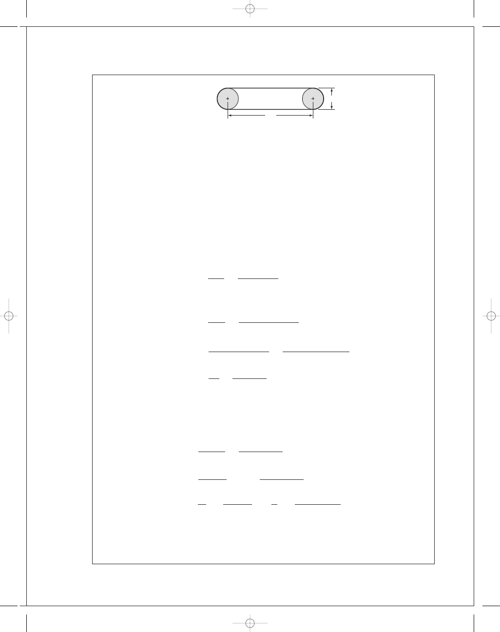
48"
192"
budynas_SM_ch17.qxd 12/06/2006 17:29 Page 423
FIRST PAGES
424
Solutions Manual • Instructor’s Solution Manual to Accompany Mechanical Engineering Design
design by reducing the initial tension, which reduces F
1
and F
2
, thereby increasing belt life.
This will bring f
to 0.80
F
1
=
(
F + F
c
) exp( f
θ) − F
c
exp( f
θ) − 1
exp( f
θ) = exp(0.80π) = 12.345
Therefore
F
1
=
(456
.1 + 77.4)(12.345) − 77.4
12
.345 − 1
= 573.7 lbf
F
2
= F
1
− F = 573.7 − 456.1 = 117.6 lbf
F
i
=
F
1
+ F
2
2
− F
c
=
573
.7 + 117.6
2
− 77.4 = 268.3 lbf
These are small reductions since f
is close to f, but improvements nevertheless.
dip
=
3C
2
w
2F
i
=
3(192
/12)
2
(0
.393)
2(268
.3)
= 0.562 in
17-4
From the last equation given in the Problem Statement,
exp( f
φ) =
1
1
− {2T/[d(a
0
− a
2
)b]
}
1
−
2T
d(a
0
− a
2
)b
exp( f
φ) = 1
2T
d(a
0
− a
2
)b
exp( f
φ) = exp( f φ) − 1
b
=
1
a
0
− a
2
2T
d
exp( f
φ)
exp( f
φ) − 1
But
2T
/d = 33 000H
d
/V
Thus,
b
=
1
a
0
− a
2
33 000H
d
V
exp( f
φ)
exp( f
φ) − 1
Q
.E.D.
17-5
Refer to Ex. 17-1 on p. 870 for the values used below.
(a) The maximum torque prior to slip is,
T
=
63 025H
nom
K
s
n
d
n
=
63 025(15)(1
.25)(1.1)
1750
= 742.8 lbf · in Ans.
The corresponding initial tension is,
F
i
=
T
D
exp( f
θ) + 1
exp( f
θ) − 1
=
742
.8
6
11
.17 + 1
11
.17 − 1
= 148.1 lbf Ans.
budynas_SM_ch17.qxd 12/06/2006 17:29 Page 424
FIRST PAGES
Chapter 17
425
(b) See Prob. 17-4 statement. The final relation can be written
b
min
=
1
F
a
C
p
C
v
− (12γ t/32.174)(V/60)
2
33 000H
a
exp( f
θ)
V [exp( f
θ) − 1]
=
1
100(0
.7)(1) − {[12(0.042)(0.13)]/32.174}(2749/60)
2
33 000(20
.6)(11.17)
2749(11
.17 − 1)
= 4.13 in Ans.
This is the minimum belt width since the belt is at the point of slip. The design must
round up to an available width.
Eq. (17-1):
θ
d
= π − 2 sin
−
1
D
− d
2C
= π − 2 sin
−
1
18
− 6
2(96)
= 3.016 511 rad
θ
D
= π + 2 sin
−
1
D
− d
2C
= π + 2 sin
−
1
18
− 6
2(96)
= 3.266 674
Eq. (17-2):
L
= [4(96)
2
− (18 − 6)
2
]
1
/
2
+
1
2
[18(3
.266 674) + 6(3.016 511)]
= 230.074 in Ans.
(c)
F =
2T
d
=
2(742
.8)
6
= 247.6 lbf
( F
1
)
a
= bF
a
C
p
C
v
= F
1
= 4.13(100)(0.70)(1) = 289.1 lbf
F
2
= F
1
− F = 289.1 − 247.6 = 41.5 lbf
F
c
= 25.6
0
.271
0
.393
= 17.7 lbf
F
i
=
F
1
+ F
2
2
− F
c
=
289
.1 + 41.5
2
− 17.7 = 147.6 lbf
Transmitted belt power H
H
=
F(V )
33 000
=
247
.6(2749)
33 000
= 20.6 hp
n
f s
=
H
H
nom
K
s
=
20
.6
15(1
.25)
= 1.1
budynas_SM_ch17.qxd 12/06/2006 17:29 Page 425
FIRST PAGES
426
Solutions Manual • Instructor’s Solution Manual to Accompany Mechanical Engineering Design
If you only change the belt width, the parameters in the following table change as shown.
Ex. 17-1
This Problem
b
6.00
4.13
w
0.393
0.271
F
c
25.6
17.6
( F
1
)
a
420
289
F
2
172.4
42
F
i
270.6
147.7
f
0.33*
0.80**
dip
0.139
0.176
*Friction underdeveloped
**Friction fully developed
17-6
The transmitted power is the same.
n-Fold
b
= 6 in b = 12 in Change
F
c
25.65
51.3
2
F
i
270.35
664.9
2.46
( F
1
)
a
420
840
2
F
2
172.4
592.4
3.44
H
a
20.62
20.62
1
n
fs
1.1
1.1
1
f
0.139
0.125
0.90
dip
0.328
0.114
0.34
If we relax F
i
to develop full friction ( f
= 0.80) and obtain longer life, then
n-Fold
b
= 6 in b = 12 in
Change
F
c
25.6
51.3
2
F
i
148.1
148.1
1
F
1
297.6
323.2
1.09
F
2
50
75.6
1.51
f
0.80
0.80
1
dip
0.255
0.503
2
budynas_SM_ch17.qxd 12/06/2006 17:29 Page 426
FIRST PAGES
Chapter 17
427
17-7
Find the resultant of F
1
and F
2
:
α = sin
−
1
D
− d
2C
sin
α =
D
− d
2C
cos
α ˙= 1 −
1
2
D
− d
2C
2
R
x
= F
1
cos
α + F
2
cos
α = (F
1
+ F
2
)
1
−
1
2
D
− d
2C
2
Ans
.
R
y
= F
1
sin
α − F
2
sin
α = (F
1
− F
2
)
D
− d
2C
Ans
.
From Ex. 17-2, d
= 16 in, D = 36 in, C = 16(12) = 192 in, F
1
= 940 lbf, F
2
= 276 lbf
α = sin
−
1
36
− 16
2(192)
= 2.9855
◦
R
x
= (940 + 276)
1
−
1
2
36
− 16
2(192)
2
= 1214.4 lbf
R
y
= (940 − 276)
36
− 16
2(192)
= 34.6 lbf
T
= (F
1
− F
2
)
d
2
= (940 − 276)
16
2
= 5312 lbf · in
17-8
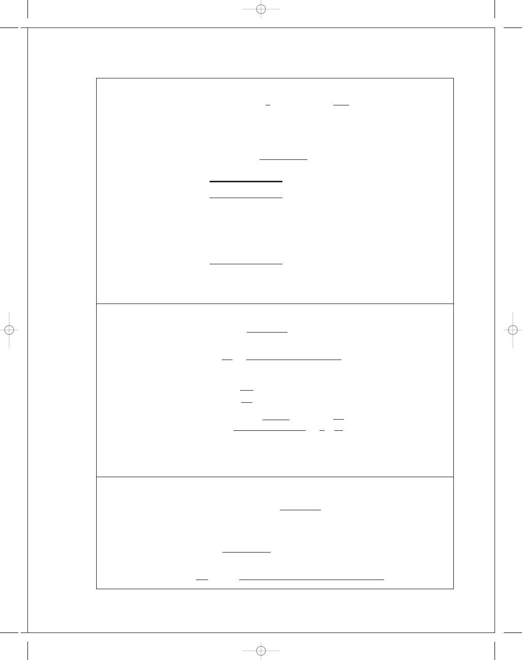
Begin with Eq. (17-10),
F
1
= F
c
+ F
i
2 exp( f
θ)
exp( f
θ) − 1
Introduce Eq. (17-9):
F
1
= F
c
+
T
D
exp( f
θ) + 1
exp( f
θ) − 1
2 exp( f
θ)
exp( f
θ) + 1
= F
c
+
2T
D
exp( f
θ)
exp( f
θ) − 1
F
1
= F
c
+ F
exp( f
θ)
exp( f
θ) − 1
d
D
C
F
1
R
x
R
y
x
y
F
2
␣
␣
budynas_SM_ch17.qxd 12/06/2006 17:29 Page 427
FIRST PAGES
428
Solutions Manual • Instructor’s Solution Manual to Accompany Mechanical Engineering Design
Now add and subtract F
c
exp( f
θ)
exp( f
θ) − 1
F
1
= F
c
+ F
c
exp( f
θ)
exp( f
θ) − 1
+ F
exp( f
θ)
exp( f
θ) − 1
− F
c
exp( f
θ)
exp( f
θ) − 1
F
1
= (F
c
+ F)
exp( f
θ)
exp( f
θ) − 1
+ F
c
− F
c
exp( f
θ)
exp( f
θ) − 1
F
1
= (F
c
+ F)
exp( f
θ)
exp( f
θ) − 1
−
F
c
exp( f
θ) − 1
F
1
=
( F
c
+ F) exp( f θ) − F
c
exp( f
θ) − 1
Q
.E.D.
From Ex. 17-2:
θ
d
= 3.037 rad, F = 664 lbf, exp( f θ) = exp[0.80(3.037)] = 11.35,
and F
c
= 73.4 lbf.
F
1
=
(73
.4 + 664)(11.35 − 73.4)
(11
.35 − 1)
= 802 lbf
F
2
= F
1
− F = 802 − 664 = 138 lbf
F
i
=
802
+ 138
2
− 73.4 = 396.6 lbf
f
=
1
θ
d
ln
F
1
− F
c
F
2
− F
c
=
1
3
.037
ln
802
− 73.4
138
− 73.4
= 0.80 Ans.
17-9
This is a good class project. Form four groups, each with a belt to design. Once each group
agrees internally, all four should report their designs including the forces and torques on the
line shaft. If you give them the pulley locations, they could design the line shaft.
17-10
If you have the students implement a computer program, the design problem selections
may differ, and the students will be able to explore them. For K
s
= 1.25, n
d
= 1.1,
d
= 14 in and D = 28 in, a polyamide A-5 belt, 8 inches wide, will do(b
min
= 6.58 in)
17-11
An efficiency of less than unity lowers the output for a given input. Since the object of the
drive is the output, the efficiency must be incorporated such that the belt’s capacity is
increased. The design power would thus be expressed as
H
d
=
H
nom
K
s
n
d
eff
Ans
.
17-12
Some perspective on the size of F
c
can be obtained from
F
c
=
w
g
V
60
2
=
12
γ bt
g
V
60
2
budynas_SM_ch17.qxd 12/06/2006 17:29 Page 428
FIRST PAGES
Chapter 17
429
An approximate comparison of non-metal and metal belts is presented in the table
below.
Non-metal
Metal
γ, lbf/in
3
0.04
0.280
b, in
5.00
1.000
t, in
0.20
0.005
The ratio
w/w
m
is
w
w
m
=
12(0
.04)(5)(0.2)
12(0
.28)(1)(0.005)
˙= 29
The second contribution to F
c
is the belt peripheral velocity which tends to be low in
metal belts used in instrument, printer, plotter and similar drives. The velocity ratio
squared influences any F
c
/(F
c
)
m
ratio.
It is common for engineers to treat F
c
as negligible compared to other tensions in the
belting problem. However, when developing a computer code, one should include F
c
.
17-13
Eq. (17-8):
F = F
1
− F
2
= (F
1
− F
c
)
exp( f
θ) − 1
exp( f
θ)
Assuming negligible centrifugal force and setting F
1
= ab from step 3,
b
min
=
F
a
exp( f
θ)
exp( f
θ) − 1
(1)
Also,
H
d
= H
nom
K
s
n
d
=
(
F)V
33 000
F =
33 000H
nom
K
s
n
d
V
Substituting into (1), b
min
=
1
a
33 000H
d
V
exp( f
θ)
exp( f
θ) − 1
Ans
.
17-14
The decision set for the friction metal flat-belt drive is:
A priori decisions
• Function:
H
nom
= 1 hp , n = 1750 rev/min , V R = 2 , C ˙= 15 in , K
s
= 1.2 ,
N
p
= 10
6
belt passes.
• Design factor:
n
d
= 1.05
• Belt material and properties:
301
/302 stainless steel
Table 17-8:
S
y
= 175 000 psi, E = 28 Mpsi, ν = 0.285
budynas_SM_ch17.qxd 12/06/2006 17:29 Page 429
FIRST PAGES
430
Solutions Manual • Instructor’s Solution Manual to Accompany Mechanical Engineering Design
• Drive geometry:
d
= 2 in, D = 4 in
• Belt thickness:
t
= 0.003 in
Design variables:
• Belt width b
• Belt loop periphery
Preliminaries
H
d
= H
nom
K
s
n
d
= 1(1.2)(1.05) = 1.26 hp
T
=
63 025(1
.26)
1750
= 45.38 lbf · in
A 15 in center-to-center distance corresponds to a belt loop periphery of 39.5 in. The
40 in loop available corresponds to a 15.254 in center distance.
θ
d
= π − 2 sin
−
1
4
− 2
2(15
.254)
= 3.010 rad
θ
D
= π + 2 sin
−
1
4
− 2
2(15
.274)
= 3.273 rad
For full friction development
exp( f
θ
d
)
= exp[0.35(3.010)] = 2.868
V
=
πdn
12
=
π(2)(1750)
12
= 916.3 ft/s
S
y
= 175 000 psi
Eq. (17-15):
S
f
= 14.17(10
6
)(10
6
)
−
0
.
407
= 51 212 psi
From selection step 3
a
=
S
f
−
Et
(1
− ν
2
)d
t
=
51 212
−
28(10
6
)(0
.003)
(1
− 0.285
2
)(2)
(0
.003)
= 16.50 lbf/in of belt width
( F
1
)
a
= ab = 16.50b
For full friction development, from Prob. 17-13,
b
min
=
F
a
exp( f
θ
d
)
exp( f
θ
d
)
− 1
F =
2T
d
=
2(45
.38)
2
= 45.38 lbf
So
b
min
=
45
.38
16
.50
2
.868
2
.868 − 1
= 4.23 in
budynas_SM_ch17.qxd 12/06/2006 17:29 Page 430
FIRST PAGES
Chapter 17
431
Decision #1:
b
= 4.5 in
F
1
= (F
1
)
a
= ab = 16.5(4.5) = 74.25 lbf
F
2
= F
1
− F = 74.25 − 45.38 = 28.87 lbf
F
i
=
F
1
+ F
2
2
=
74
.25 + 28.87
2
= 51.56 lbf
Existing friction
f
=
1
θ
d
ln
F
1
F
2
=
1
3
.010
ln
74
.25
28
.87
= 0.314
H
t
=
(
F)V
33 000
=
45
.38(916.3)
33 000
= 1.26 hp
n
f s
=
H
t
H
nom
K
s
=
1
.26
1(1
.2)
= 1.05
This is a non-trivial point. The methodology preserved the factor of safety corresponding
to n
d
= 1.1 even as we rounded b
min
up to b .
Decision #2 was taken care of with the adjustment of the center-to-center distance to
accommodate the belt loop. Use Eq. (17-2) as is and solve for C to assist in this. Remem-
ber to subsequently recalculate
θ
d
and
θ
D
.
17-15
Decision set:
A priori decisions
• Function:
H
nom
= 5 hp, N = 1125 rev/min, V R = 3, C ˙= 20 in, K
s
= 1.25,
N
p
= 10
6
belt passes
• Design factor:
n
d
= 1.1
• Belt material:
BeCu,
S
y
= 170 000 psi, E = 17(10
6
) psi,
ν = 0.220
• Belt geometry:
d
= 3 in, D = 9 in
• Belt thickness:
t
= 0.003 in
Design decisions
• Belt loop periphery
• Belt width b
Preliminaries:
H
d
= H
nom
K
s
n
d
= 5(1.25)(1.1) = 6.875 hp
T
=
63 025(6
.875)
1125
= 385.2 lbf · in
Decision #1:
Choose a 60-in belt loop with a center-to-center distance of 20.3 in.
θ
d
= π − 2 sin
−
1
9
− 3
2(20
.3)
= 2.845 rad
θ
D
= π + 2 sin
−
1
9
− 3
2(20
.3)
= 3.438 rad
budynas_SM_ch17.qxd 12/06/2006 17:29 Page 431
FIRST PAGES
432
Solutions Manual • Instructor’s Solution Manual to Accompany Mechanical Engineering Design
For full friction development:
exp( f
θ
d
)
= exp[0.32(2.845)] = 2.485
V
=
πdn
12
=
π(3)(1125)
12
= 883.6 ft/min
S
f
= 56 670 psi
From selection step 3
a
=
S
f
−
Et
(1
− ν
2
)d
t
=
56 670
−
17(10
6
)(0
.003)
(1
− 0.22
2
)(3)
(0
.003) = 116.4 lbf/in
F =
2T
d
=
2(385
.2)
3
= 256.8 lbf
b
min
=
F
a
exp( f
θ
d
)
exp( f
θ
d
)
− 1
=
256
.8
116
.4
2
.485
2
.485 − 1
= 3.69 in
Decision #2:
b
= 4 in
F
1
= (F
1
)
a
= ab = 116.4(4) = 465.6 lbf
F
2
= F
1
− F = 465.6 − 256.8 = 208.8 lbf
F
i
=
F
1
+ F
2
2
=
465
.6 + 208.8
2
= 337.3 lbf
Existing friction
f
=
1
θ
d
ln
F
1
F
2
=
1
2
.845
ln
465
.6
208
.8
= 0.282
H
=
(
F)V
33 000
=
256
.8(883.6)
33 000
= 6.88 hp
n
f s
=
H
5(1
.25)
=
6
.88
5(1
.25)
= 1.1
F
i
can be reduced only to the point at which f
= f = 0.32. From Eq. (17-9)
F
i
=
T
d
exp( f
θ
d
)
+ 1
exp( f
θ
d
)
− 1
=
385
.2
3
2
.485 + 1
2
.485 − 1
= 301.3 lbf
Eq. (17-10):
F
1
= F
i
2 exp( f
θ
d
)
exp( f
θ
d
)
+ 1
= 301.3
2(2
.485)
2
.485 + 1
= 429.7 lbf
F
2
= F
1
− F = 429.7 − 256.8 = 172.9 lbf
and
f
= f = 0.32
17-16
This solution is the result of a series of five design tasks involving different belt thick-
nesses. The results are to be compared as a matter of perspective. These design tasks are
accomplished in the same manner as in Probs. 17-14 and 17-15 solutions.
budynas_SM_ch17.qxd 12/06/2006 17:29 Page 432
FIRST PAGES
Chapter 17
433
The details will not be presented here, but the table is provided as a means of learning.
Five groups of students could each be assigned a belt thickness. You can form a table from
their results or use the table below
t, in
0.002
0.003
0.005
0.008
0.010
b
4.000
3.500
4.000
1.500
1.500
CD
20.300
20.300
20.300
18.700
20.200
a
109.700
131.900
110.900
194.900
221.800
d
3.000
3.000
3.000
5.000
6.000
D
9.000
9.000
9.000
15.000
18.000
F
i
310.600
333.300
315.200
215.300
268.500
F
1
439.000
461.700
443.600
292.300
332.700
F
2
182.200
209.000
186.800
138.200
204.300
n
f s
1.100
1.100
1.100
1.100
1.100
L
60.000
60.000
60.000
70.000
80.000
f
0.309
0.285
0.304
0.288
0.192
F
i
301.200
301.200
301.200
195.700
166.600
F
1
429.600
429.600
429.600
272.700
230.800
F
2
172.800
172.800
172.800
118.700
102.400
f
0.320
0.320
0.320
0.320
0.320
The first three thicknesses result in the same adjusted F
i
, F
1
and F
2
(why?). We have no
figure of merit, but the costs of the belt and the pulleys is about the same for these three
thicknesses. Since the same power is transmitted and the belts are widening, belt forces
are lessening.
17-17
This is a design task. The decision variables would be belt length and belt section, which
could be combined into one, such as B90. The number of belts is not an issue.
We have no figure of merit, which is not practical in a text for this application. I sug-
gest you gather sheave dimensions and costs and V-belt costs from a principal vendor and
construct a figure of merit based on the costs. Here is one trial.
Preliminaries: For a single V-belt drive with H
nom
= 3 hp, n = 3100 rev/min,
D
= 12 in, and d = 6.2 in, choose a B90 belt, K
s
= 1.3 and n
d
= 1.
L
p
= 90 + 1.8 = 91.8 in
Eq. (17-16b):
C
= 0.25
91
.8 −
π
2
(12
+ 6.2)
+
91
.8 −
π
2
(12
+ 6.2)
2
− 2(12 − 6.2)
2
= 31.47 in
θ
d
= π − 2 sin
−
1
12
− 6.2
2(31
.47)
= 2.9570 rad
exp( f
θ
d
)
= exp[0.5123(2.9570)] = 4.5489
V
=
πdn
12
=
π(6.2)(3100)
12
= 5031.8 ft/min
budynas_SM_ch17.qxd 12/06/2006 17:29 Page 433
FIRST PAGES
434
Solutions Manual • Instructor’s Solution Manual to Accompany Mechanical Engineering Design
Table 17-13:
Angle
θ = θ
d
180°
π
= (2.957 rad)
180°
π
= 169.42°
The footnote regression equation gives K
1
without interpolation:
K
1
= 0.143 543 + 0.007 468(169.42°) − 0.000 015 052(169.42°)
2
= 0.9767
The design power is
H
d
= H
nom
K
s
n
d
= 3(1.3)(1) = 3.9 hp
From Table 17-14 for B90, K
2
= 1. From Table 17-12 take a marginal entry of H
tab
= 4,
although extrapolation would give a slightly lower H
tab
.
Eq. (17-17):
H
a
= K
1
K
2
H
tab
= 0.9767(1)(4) = 3.91 hp
The allowable
F
a
is given by
F
a
=
63 025H
a
n(d
/2)
=
63 025(3
.91)
3100(6
.2/2)
= 25.6 lbf
The allowable torque T
a
is
T
a
=
F
a
d
2
=
25
.6(6.2)
2
= 79.4 lbf · in
From Table 17-16, K
c
= 0.965. Thus, Eq. (17-21) gives,
F
c
= 0.965
5031
.8
1000
2
= 24.4 lbf
At incipient slip, Eq. (17-9) provides:
F
i
=
T
d
exp( f
θ) + 1
exp( f
θ) − 1
=
79
.4
6
.2
4
.5489 + 1
4
.5489 − 1
= 20.0 lbf
Eq. (17-10):
F
1
= F
c
+ F
i
2 exp( f
θ)
exp( f
θ) + 1
= 24.4 + 20
2(4
.5489)
4
.5489 + 1
= 57.2 lbf
Thus,
F
2
= F
1
− F
a
= 57.2 − 25.6 = 31.6 lbf
Eq. (17-26):
n
f s
=
H
a
N
b
H
d
=
(3
.91)(1)
3
.9
= 1.003 Ans.
If we had extrapolated for H
tab
, the factor of safety would have been slightly less
than one.
Life
Use Table 17-16 to find equivalent tensions T
1
and T
2
.
T
1
= F
1
+ (F
b
)
1
= F
1
+
K
b
d
= 57.2 +
576
6
.2
= 150.1 lbf
T
2
= F
1
+ (F
b
)
2
= F
1
+
K
b
D
= 57.2 +
576
12
= 105.2 lbf
budynas_SM_ch17.qxd 12/06/2006 17:29 Page 434
FIRST PAGES
Chapter 17
435
From Eq. (17-27), the number of belt passes is:
N
P
=
1193
150
.1
−
10
.
929
+
1193
105
.2
−
10
.
929
−
1
= 6.76(10
9
)
From Eq. (17-28) for N
P
> 10
9
,
t
=
N
P
L
p
720V
>
10
9
(91
.8)
720(5031
.8)
t
> 25 340 h Ans.
Suppose n
f s
was too small. Compare these results with a 2-belt solution.
H
tab
= 4 hp/belt, T
a
= 39.6 lbf · in/belt,
F
a
= 12.8 lbf/belt, H
a
= 3.91 hp/belt
n
f s
=
N
b
H
a
H
d
=
N
b
H
a
H
nom
K
s
=
2(3
.91)
3(1
.3)
= 2.0
Also,
F
1
= 40.8 lbf/belt,
F
2
= 28.0 lbf/belt,
F
i
= 9.99 lbf/belt,
F
c
= 24.4 lbf/belt
( F
b
)
1
= 92.9 lbf/belt,
( F
b
)
2
= 48 lbf/belt
T
1
= 133.7 lbf/belt,
T
2
= 88.8 lbf/belt
N
P
= 2.39(10
10
) passes,
t
> 605 600 h
Initial tension of the drive:
( F
i
)
drive
= N
b
F
i
= 2(9.99) = 20 lbf
17-18
Given: two B85 V-belts with d
= 5.4 in, D = 16 in, n = 1200 rev/min, and K
s
= 1.25
Table 17-11:
L
p
= 85 + 1.8 = 86.8 in
Eq. (17-17b):
C
= 0.25
86
.8 −
π
2
(16
+ 5.4)
+
86
.8 −
π
2
(16
+ 5.4)
2
− 2(16 − 5.4)
2
= 26.05 in Ans.
Eq. (17-1):
θ
d
= 180° − 2 sin
−
1
16
− 5.4
2(26
.05)
= 156.5°
From table 17-13 footnote:
K
1
= 0.143 543 + 0.007 468(156.5°) − 0.000 015 052(156.5°)
2
= 0.944
Table 17-14:
K
2
= 1
Belt speed:
V
=
π(5.4)(1200)
12
= 1696 ft/min
budynas_SM_ch17.qxd 12/06/2006 17:29 Page 435
FIRST PAGES
436
Solutions Manual • Instructor’s Solution Manual to Accompany Mechanical Engineering Design
Use Table 17-12 to interpolate for H
tab
.
H
tab
= 1.59 +
2
.62 − 1.59
2000
− 1000
(1696
− 1000) = 2.31 hp/belt
H
a
= K
1
K
2
N
b
H
tab
= 1(0.944)(2)(2.31) = 4.36 hp
Assuming n
d
= 1
H
d
= K
s
H
nom
n
d
= 1.25(1)H
nom
For a factor of safety of one,
H
a
= H
d
4
.36 = 1.25H
nom
H
nom
=
4
.36
1
.25
= 3.49 hp Ans.
17-19
Given: H
nom
= 60 hp, n = 400 rev/min, K
s
= 1.4, d = D = 26 in on 12 ft centers.
Design task: specify V-belt and number of strands (belts). Tentative decision: Use D360 belts.
Table 17-11:
L
p
= 360 + 3.3 = 363.3 in
Eq. (17-16 b):
C
= 0.25
363
.3 −
π
2
(26
+ 26)
+
363
.3 −
π
2
(26
+ 26)
2
− 2(26 − 26)
2
= 140.8 in (nearly 144 in)
θ
d
= π, θ
D
= π, exp[0.5123π] = 5.0,
V
=
πdn
12
=
π(26)(400)
12
= 2722.7 ft/min
Table 17-13: For
θ = 180°, K
1
= 1
Table 17-14: For D360,
K
2
= 1.10
Table 17-12: H
tab
= 16.94 hp by interpolation
Thus,
H
a
= K
1
K
2
H
tab
= 1(1.1)(16.94) = 18.63 hp
H
d
= K
s
H
nom
= 1.4(60) = 84 hp
Number of belts, N
b
N
b
=
K
s
H
nom
K
1
K
2
H
tab
=
H
d
H
a
=
84
18
.63
= 4.51
Round up to five belts. It is left to the reader to repeat the above for belts such as C360
and E360.
F
a
=
63 025H
a
n(d
/2)
=
63 025(18
.63)
400(26
/2)
= 225.8 lbf/belt
T
a
=
(
F
a
)d
2
=
225
.8(26)
2
= 2935 lbf · in/belt
budynas_SM_ch17.qxd 12/06/2006 17:29 Page 436
FIRST PAGES
Chapter 17
437
Eq. (17-21):
F
c
= 3.498
V
1000
2
= 3.498
2722
.7
1000
2
= 25.9 lbf/belt
At fully developed friction, Eq. (17-9) gives
F
i
=
T
d
exp( f
θ) + 1
exp( f
θ) − 1
=
2935
26
5
+ 1
5
− 1
= 169.3 lbf/belt
Eq. (17-10): F
1
= F
c
+ F
i
2 exp( f
θ)
exp( f
θ) + 1
= 25.9 + 169.3
2(5)
5
+ 1
= 308.1 lbf/belt
F
2
= F
1
− F
a
= 308.1 − 225.8 = 82.3 lbf/belt
n
f s
=
H
a
N
b
H
d
=
(185
.63)
84
= 1.109 Ans.
Reminder: Initial tension is for the drive
( F
i
)
drive
= N
b
F
i
= 5(169.3) = 846.5 lbf
A 360 belt is at the right-hand edge of the range of center-to-center pulley distances.
D
≤ C ≤ 3(D + d)
26
≤ C ≤ 3(26 + 26)
17-20
Preliminaries: D
˙= 60 in, 14-in wide rim, H
nom
= 50 hp, n = 875 rev/min, K
s
= 1.2,
n
d
= 1.1, m
G
= 875/170 = 5.147, d ˙= 60/5.147 = 11.65 in
(a) From Table 17-9, an 11-in sheave exceeds C-section minimum diameter and pre-
cludes D- and E-section V-belts.
Decision: Use d
= 11 in, C270 belts
Table 17-11:
L
p
= 270 + 2.9 = 272.9 in
C
= 0.25
272
.9 −
π
2
(60
+ 11)
+
272
.9 −
π
2
(60
+ 11)
2
− 2(60 − 11)
2
= 76.78 in
This fits in the range
D
< C < 3(D + d)
60
< C < 3(60 + 11)
60 in
< C < 213 in
θ
d
= π − 2 sin
−
1
60
− 11
2(76
.78)
= 2.492 rad
θ
D
= π + 2 sin
−
1
60
− 11
2(76
.78)
= 3.791 rad
exp[0
.5123(2.492)] = 3.5846
budynas_SM_ch17.qxd 12/06/2006 17:29 Page 437
FIRST PAGES
438
Solutions Manual • Instructor’s Solution Manual to Accompany Mechanical Engineering Design
For the flat on flywheel
exp[0
.13(3.791)] = 1.637
V
=
πdn
12
=
π(11)(875)
12
= 2519.8 ft/min
Table 17-13: Regression equation gives K
1
= 0.90
Table 17-14:
K
2
= 1.15
Table 17-12:
H
tab
= 7.83 hp/belt by interpolation
Eq. (17-17):
H
a
= K
1
K
2
H
tab
= 0.905(1.15)(7.83) = 8.15 hp
Eq. (17-19):
H
d
= H
nom
K
s
n
d
= 50(1.2)(1.1) = 66 hp
Eq. (17-20):
N
b
=
H
d
H
a
=
66
8
.15
= 8.1 belts
Decision: Use 9 belts. On a per belt basis,
F
a
=
63 025H
a
n(d
/2)
=
63 025(8
.15)
875(11
/2)
= 106.7 lbf/belt
T
a
=
F
a
d
2
=
106
.7(11)
2
= 586.9 lbf per belt
F
c
= 1.716
V
1000
2
= 1.716
2519
.8
1000
2
= 10.9 lbf/belt
At fully developed friction, Eq. (17-9) gives
F
i
=
T
d
exp( f
θ
d
)
+ 1
exp( f
θ
d
)
− 1
=
586
.9
11
3
.5846 + 1
3
.5846 − 1
= 94.6 lbf/belt
Eq. (17-10):
F
1
= F
c
+ F
i
2 exp( f
θ
d
)
exp( f
θ
d
)
+ 1
= 10.9 + 94.6
2(3
.5846)
3
.5846 + 1
= 158.8 lbf/belt
F
2
= F
1
− F
a
= 158.8 − 106.7 = 52.1 lbf/belt
n
f s
=
N
b
H
a
H
d
=
9(8
.15)
66
= 1.11 O.K. Ans.
Durability:
( F
b
)
1
= 145.45 lbf/belt, (F
b
)
2
= 76.7 lbf/belt
T
1
= 304.4 lbf/belt,
T
2
= 185.6 lbf/belt
and
t
> 150 000 h
Remember:
( F
i
)
drive
= 9(94.6) = 851.4 lbf
Table 17-9:
C-section belts are 7
/8
"
wide. Check sheave groove spacing to see if
14
"
-width is accommodating.
budynas_SM_ch17.qxd 12/06/2006 17:29 Page 438
FIRST PAGES
Chapter 17
439
(b) The fully developed friction torque on the flywheel using the flats of the V-belts is
T
flat
= F
i
exp( f
θ) − 1
exp( f
θ) + 1
= 60(94.6)
1
.637 − 1
1
.637 + 1
= 1371 lbf · in per belt
The flywheel torque should be
T
fly
= m
G
T
a
= 5.147(586.9) = 3021 lbf · in per belt
but it is not. There are applications, however, in which it will work. For example,
make the flywheel controlling. Yes.
Ans.
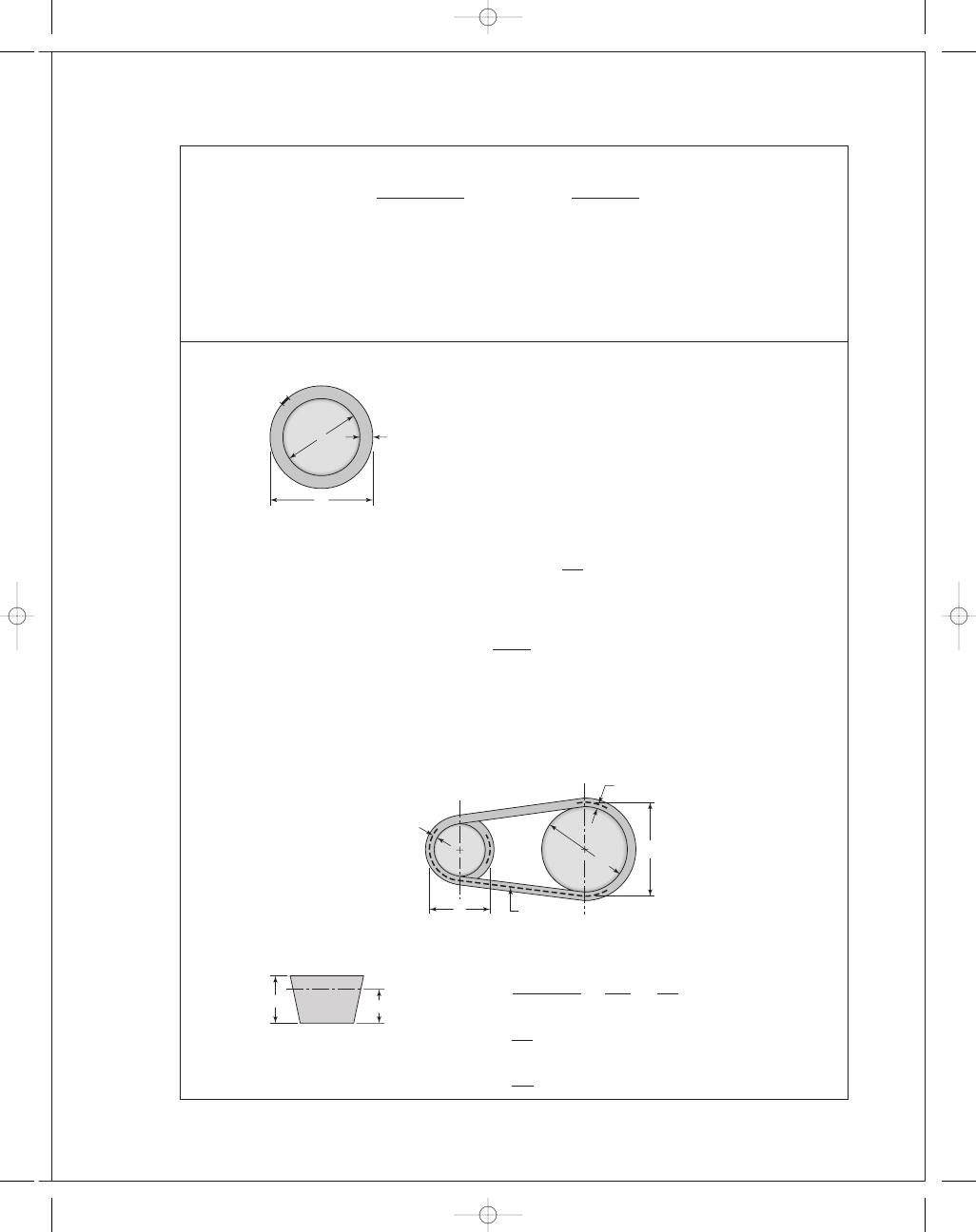
17-21
(a)
S is the spliced-in string segment length
D
e
is the equatorial diameter
D
is the spliced string diameter
δ is the radial clearance
S
+ π D
e
= π D
= π(D
e
+ 2δ) = π D
e
+ 2πδ
From which
δ =
S
2
π
The radial clearance is thus independent of D
e
.
δ =
12(6)
2
π
= 11.5 in Ans.
This is true whether the sphere is the earth, the moon or a marble. Thinking in terms
of a radial or diametral increment removes the basic size from the problem. Viewpoint
again!
(b) and (c)
Table 17-9: For an E210 belt, the thickness is 1 in.
d
P
− d
i
=
210
+ 4.5
π
−
210
π
=
4
.5
π
2
δ =
4
.5
π
δ =
4
.5
2
π
= 0.716 in
0.716"
1"
d
p
D
p
␦
␦
Pitch surface
60"
D
⬘
S
D
e
␦
budynas_SM_ch17.qxd 12/06/2006 17:29 Page 439
FIRST PAGES
440
Solutions Manual • Instructor’s Solution Manual to Accompany Mechanical Engineering Design
The pitch diameter of the flywheel is
D
P
− 2δ = D
D
P
= D + 2δ = 60 + 2(0.716) = 61.43 in
We could make a table:
Diametral
Section
Growth
A
B
C
D
E
2
δ
1
.3
π
1
.8
π
2
.9
π
3
.3
π
4
.5
π
The velocity ratio for the D-section belt of Prob. 17-20 is
m
G
=
D
+ 2δ
d
=
60
+ 3.3/π
11
= 5.55 Ans.
for the V-flat drive as compared to m
a
= 60/11 = 5.455 for the VV drive.
The pitch diameter of the pulley is still d
= 11 in, so the new angle of wrap, θ
d
, is
θ
d
= π − 2 sin
−
1
D
+ 2δ − d
2C
Ans
.
θ
D
= π + 2 sin
−
1
D
+ 2δ − d
2C
Ans
.
Equations (17-16a) and (17-16b) are modified as follows
L
p
= 2C +
π
2
( D
+ 2δ + d) +
( D
+ δ − d)
2
4C
Ans
.
C
p
= 0.25
L
p
−
π
2
( D
+ 2δ + d)
+
L
p
−
π
2
( D
+ 2δ + d)
2
− 2(D + 2δ − d)
2
Ans
.
The changes are small, but if you are writing a computer code for a V-flat drive,
remember that
θ
d
and
θ
D
changes are exponential.
17-22
This design task involves specifying a drive to couple an electric motor running at
1720 rev/min to a blower running at 240 rev/min, transmitting two horsepower with a
center distance of at least 22 inches. Instead of focusing on the steps, we will display two
different designs side-by-side for study. Parameters are in a “per belt” basis with per drive
quantities shown along side, where helpful.
budynas_SM_ch17.qxd 12/06/2006 17:29 Page 440
FIRST PAGES
Chapter 17
441
Parameter
Four A-90 Belts
Two A-120 Belts
m
G
7.33
7.142
K
s
1.1
1.1
n
d
1.1
1.1
K
1
0.877
0.869
K
2
1.05
1.15
d, in
3.0
4.2
D, in
22
30
θ
d
, rad
2.333
2.287
V
, ft/min
1350.9
1891
exp( f
θ
d
)
3.304
3.2266
L
p
, in
91.3
101.3
C, in
24.1
31
H
tab
, uncorr.
0.783
1.662
N
b
H
tab
, uncorr.
3.13
3.326
T
a
, lbf
· in
26.45(105.8)
60.87(121.7)
F
a
, lbf
17.6(70.4)
29.0(58)
H
a
, hp
0.721(2.88)
1.667(3.33)
n
f s
1.192
1.372
F
1
, lbf
26.28(105.2)
44(88)
F
2
, lbf
8.67(34.7)
15(30)
( F
b
)
1
, lbf
73.3(293.2)
52.4(109.8)
( F
b
)
2
, lbf
10(40)
7.33(14.7)
F
c
, lbf
1.024
2.0
F
i
, lbf
16.45(65.8)
27.5(55)
T
1
, lbf
· in
99.2
96.4
T
2
, lbf
· in
36.3
57.4
N
, passes
1
.61(10
9
)
2
.3(10
9
)
t
> h
93 869
89 080
Conclusions:
• Smaller sheaves lead to more belts.
• Larger sheaves lead to larger D and larger V.
• Larger sheaves lead to larger tabulated power.
• The discrete numbers of belts obscures some of the variation. The factors of safety
exceed the design factor by differing amounts.
17-23
In Ex. 17-5 the selected chain was 140-3, making the pitch of this 140 chain14
/8 = 1.75 in.
Table 17-19 confirms.
17-24
(a) Eq. (17-32):
H
1
= 0.004N
1
.
08
1
n
0
.
9
1
p
(
3
−
0
.
07
p)
Eq. (17-33):
H
2
=
1000K
r
N
1
.
5
1
p
0
.
8
n
1
.
5
1
budynas_SM_ch17.qxd 12/06/2006 17:29 Page 441
FIRST PAGES
442
Solutions Manual • Instructor’s Solution Manual to Accompany Mechanical Engineering Design
Equating and solving for n
1
gives
n
1
=
0
.25(10
6
) K
r
N
0
.
42
1
p
(
2
.
2
−
0
.
07
p)
1
/
2
.
4
Ans
.
(b) For a No. 60 chain, p
= 6/8 = 0.75 in, N
1
= 17, K
r
= 17
n
1
=
0
.25(10
6
)(17)(17)
0
.
42
0
.75
[2
.
2
−
0
.
07
(
0
.
75
)
]
1
/
2
.
4
= 1227 rev/min Ans.
Table 17-20 confirms that this point occurs at 1200
± 200 rev/min.
(c) Life predictions using Eq. (17-40) are possible at speeds greater than 1227 rev/min.
Ans.
17-25
Given: a double strand No. 60 roller chain with p
= 0.75 in, N
1
= 13 teeth at 300 rev/min,
N
2
= 52 teeth.
(a) Table 17-20:
H
tab
= 6.20 hp
Table 17-22:
K
1
= 0.75
Table 17-23:
K
2
= 1.7
Use
K
s
= 1
Eq. (17-37):
H
a
= K
1
K
2
H
tab
= 0.75(1.7)(6.20) = 7.91 hp Ans.
(b) Eqs. (17-35) and (17-36) with L
/p = 82
A
=
13
+ 52
2
− 82 = −49.5
[
C
=
p
4
49.5 +
49
.5
2
− 8
52
− 13
2
π
2
= 23.95p
C
= 23.95(0.75) = 17.96 in, round up to 18 in Ans.
(c) For 30 percent less power transmission,
H
= 0.7(7.91) = 5.54 hp
T
=
63 025(5
.54)
300
= 1164 lbf · in Ans.
Eq. (17-29):
D
=
0
.75
sin(180
◦
/13)
= 3.13 in
F
=
T
r
=
1164
3
.13/2
= 744 lbf Ans.
budynas_SM_ch17.qxd 12/06/2006 17:29 Page 442
FIRST PAGES
Chapter 17
443
17-26
Given: No. 40-4 chain, N
1
= 21 teeth for n = 2000 rev/min, N
2
= 84 teeth,
h
= 20 000 hours.
(a) Chain pitch is p
= 4/8 = 0.500 in and C ˙= 20 in.
Eq. (17-34):
L
p
=
2(20)
0
.5
+
21
+ 84
2
+
(84
− 21)
2
4
π
2
(20
/0.5)
= 135 pitches (or links)
L
= 135(0.500) = 67.5 in Ans.
(b) Table 17-20:
H
tab
= 7.72 hp (post-extreme power)
Eq. (17-40): Since K
1
is required, the N
3
.
75
1
term is omitted.
const
=
7
.72
2
.
5
(15 000)
135
= 18 399
H
tab
=
18 399(135)
20 000
1
/
2
.
5
= 6.88 hp Ans.
(c) Table 17-22:
K
1
=
21
17
1
.
5
= 1.37
Table 17-23:
K
2
= 3.3
H
a
= K
1
K
2
H
tab
= 1.37(3.3)(6.88) = 31.1 hp Ans.
(d)
V
=
N
1
pn
12
=
21(0
.5)(2000)
12
= 1750 ft/min
F
1
=
33 000(31
.1)
1750
= 586 lbf Ans.
17-27
This is our first design/selection task for chain drives. A possible decision set:
A priori decisions
• Function: H
nom
, n
1
, space, life, K
s
• Design factor: n
d
• Sprockets: Tooth counts N
1
and N
2
, factors K
1
and K
2
Decision variables
• Chain number
• Strand count
• Lubrication type
• Chain length in pitches
Function: Motor with H
nom
= 25 hp at n = 700 rev/min; pump at n = 140 rev/min;
m
G
= 700/140 = 5
Design Factor: n
d
= 1.1
Sprockets: Tooth count N
2
= m
G
N
1
= 5(17) = 85 teeth–odd and unavailable. Choose
84 teeth. Decision: N
1
= 17, N
2
= 84
budynas_SM_ch17.qxd 12/06/2006 17:29 Page 443
FIRST PAGES
444
Solutions Manual • Instructor’s Solution Manual to Accompany Mechanical Engineering Design
Evaluate K
1
and K
2
Eq. (17-38):
H
d
= H
nom
K
s
n
d
Eq. (17-37):
H
a
= K
1
K
2
H
tab
Equate H
d
to H
a
and solve for H
tab
:
H
tab
=
K
s
n
d
H
nom
K
1
K
2
Table 17-22:
K
1
= 1
Table 17-23:
K
2
= 1, 1.7, 2.5, 3.3 for 1 through 4 strands
H
tab
=
1
.5(1.1)(25)
(1)K
2
=
41
.25
K
2
Prepare a table to help with the design decisions:
Chain
Lub.
Strands
K
2
H
tab
No.
H
tab
n
f s
Type
1
1.0
41.3
100
59.4
1.58
B
2
1.7
24.3
80
31.0
1.40
B
3
2.5
16.5
80
31.0
2.07
B
4
3.3
12.5
60
13.3
1.17
B
Design Decisions
We need a figure of merit to help with the choice. If the best was 4 strands of No. 60
chain, then
Decision #1 and #2: Choose four strand No. 60 roller chain with n
f s
= 1.17.
n
f s
=
K
1
K
2
H
tab
K
s
H
nom
=
1(3
.3)(13.3)
1
.5(25)
= 1.17
Decision #3: Choose Type B lubrication
Analysis:
Table 17-20:
H
tab
= 13.3 hp
Table 17-19:
p
= 0.75 in
Try C
= 30 in in Eq. (17-34):
L
p
=
2C
p
+
N
1
+ N
2
2
+
(N
2
− N
1
)
2
4
π
2
C
/p
= 2(30/0.75) +
17
+ 84
2
+
(84
− 17)
2
4
π
2
(30
/0.75)
= 133.3 → 134
From Eq. (17-35) with p
= 0.75 in,C = 30.26 in.
Decision #4: Choose C
= 30.26 in.
budynas_SM_ch17.qxd 12/06/2006 17:29 Page 444
FIRST PAGES
Chapter 17
445
17-28
Follow the decision set outlined in Prob. 17-27 solution. We will form two tables, the first
for a 15 000 h life goal, and a second for a 50 000 h life goal. The comparison is useful.
Function: H
nom
= 50 hp at n = 1800 rev/min, n
pump
= 900 rev/min
m
G
= 1800/900 = 2, K
s
= 1.2
life
= 15 000 h, then repeat with life = 50 000 h
Design factor: n
d
= 1.1
Sprockets: N
1
= 19 teeth, N
2
= 38 teeth
Table 17-22 (post extreme):
K
1
=
N
1
17
1
.
5
=
19
17
1
.
5
= 1.18
Table 17-23:
K
2
= 1, 1.7, 2.5, 3.3, 3.9, 4.6, 6.0
Decision variables for 15 000 h life goal:
H
tab
=
K
s
n
d
H
nom
K
1
K
2
=
1
.2(1.1)(50)
1
.18K
2
=
55
.9
K
2
(1)
n
f s
=
K
1
K
2
H
tab
K
s
H
nom
=
1
.18K
2
H
tab
1
.2(50)
= 0.0197K
2
H
tab
Form a table for a 15 000 h life goal using these equations.
K
2
H
tab
Chain #
H
tab
n
f s
Lub
1
1.0
55.90
120
21.6
0.423
C
2
1.7
32.90
120
21.6
0.923
C
3
2.5
22.40
120
21.6
1.064
C
4
3.3
16.90
120
21.6
1.404
C
5
3.9
14.30
80
15.6
1.106
C
6
4.6
12.20
60
12.4
1.126
C
8
6.0
9.32
60
12.4
1.416
C
There are 4 possibilities where n
f s
≥ 1.1
Decision variables for 50 000 h life goal
From Eq. (17-40), the power-life tradeoff is:
(H
tab
)
2
.5
15 000
= (H
tab
)
2
.5
50 000
H
tab
=
15 000
50 000
( H
tab
)
2
.
5
1
/
2
.
5
= 0.618 H
tab
Substituting from (1),
H
tab
= 0.618
55
.9
K
2
=
34
.5
K
2
budynas_SM_ch17.qxd 12/06/2006 17:29 Page 445
FIRST PAGES
446
Solutions Manual • Instructor’s Solution Manual to Accompany Mechanical Engineering Design
The H
notation is only necessary because we constructed the first table, which we nor-
mally would not do.
n
f s
=
K
1
K
2
H
tab
K
s
H
nom
=
K
1
K
2
(0
.618H
tab
)
K
s
H
nom
= 0.618[(0.0197)K
2
H
tab
]
= 0.0122K
2
H
tab
Form a table for a 50 000 h life goal.
K
2
H
tab
Chain #
H
tab
n
f s
Lub
1
1.0
34.50
120
21.6
0.264
C
2
1.7
20.30
120
21.6
0.448
C
3
2.5
13.80
120
21.6
0.656
C
4
3.3
10.50
120
21.6
0.870
C
5
3.9
8.85
120
21.6
1.028
C
6
4.6
7.60
120
21.6
1.210
C
8
6.0
5.80
80
15.6
1.140
C
There are two possibilities in the second table with n
f s
≥ 1.1. (The tables allow for the
identification of a longer life one of the outcomes.) We need a figure of merit to help with
the choice; costs of sprockets and chains are thus needed, but is more information than
we have.
Decision #1: #80 Chain (smaller installation)
Ans.
n
f s
= 0.0122K
2
H
tab
= 0.0122(8.0)(15.6) = 1.14 O.K.
Decision #2: 8-Strand, No. 80
Ans.
Decision #3: Type C
Lubrication
Ans.
Decision #4: p
= 1.0 in, C is in midrange of 40 pitches
L
p
=
2C
p
+
N
1
+ N
2
2
+
( N
2
− N
1
)
2
4
π
2
C
/p
= 2(40) +
19
+ 38
2
+
(38
− 19)
2
4
π
2
(40)
= 108.7 ⇒ 110 even integer Ans.
Eq. (17-36):
A
=
N
1
+ N
2
2
−
L
p
=
19
+ 38
2
− 110 = −81.5
Eq. (17-35):
C
p
=
1
4
81.5 +
81
.5
2
− 8
38
− 19
2
π
2
= 40.64
C
= p(C/p) = 1.0(40.64) = 40.64 in (for reference) Ans.
budynas_SM_ch17.qxd 12/06/2006 17:29 Page 446
FIRST PAGES
Chapter 17
447
17-29
The objective of the problem is to explore factors of safety in wire rope. We will express
strengths as tensions.
(a) Monitor steel 2-in 6
× 19 rope, 480 ft long
Table 17-2: Minimum diameter of a sheave is 30d
= 30(2) = 60 in, preferably
45(2)
= 90 in. The hoist abuses the wire when it is bent around a sheave. Table 17-24
gives the nominal tensile strength as 106 kpsi. The ultimate load is
F
u
= (S
u
)
nom
A
nom
= 106
π(2)
2
4
= 333 kip Ans.
The tensile loading of the wire is given by Eq. (17-46)
F
t
=
W
m
+ wl
1
+
a
g
W
= 4(2) = 8 kip, m = 1
Table (17-24):
wl = 1.60d
2
l
= 1.60(2
2
)(480)
= 3072 lbf or 3.072 kip
Therefore,
F
t
= (8 + 3.072)
1
+
2
32
.2
= 11.76 kip Ans.
Eq. (17-48):
F
b
=
E
r
d
w
A
m
D
and for the 72-in drum
F
b
=
12(10
6
)(2
/13)(0.38)(2
2
)(10
−
3
)
72
= 39 kip Ans.
For use in Eq. (17-44), from Fig. 17-21
( p
/S
u
)
= 0.0014
S
u
= 240 kpsi, p. 908
F
f
=
0
.0014(240)(2)(72)
2
= 24.2 kip Ans.
(b) Factors of safety
Static, no bending:
n
=
F
u
F
t
=
333
11
.76
= 28.3 Ans.
Static, with bending:
Eq. (17-49):
n
s
=
F
u
− F
b
F
t
=
333
− 39
11
.76
= 25.0 Ans.
budynas_SM_ch17.qxd 12/06/2006 17:29 Page 447
FIRST PAGES
448
Solutions Manual • Instructor’s Solution Manual to Accompany Mechanical Engineering Design
Fatigue without bending:
n
f
=
F
f
F
t
=
24
.2
11
.76
= 2.06 Ans.
Fatigue, with bending:
For a life of 0.1(10
6
) cycles, from Fig. 17-21
( p
/S
u
)
= 4/1000 = 0.004
F
f
=
0
.004(240)(2)(72)
2
= 69.1 kip
Eq. (17-50):
n
f
=
69
.1 − 39
11
.76
= 2.56 Ans.
If we were to use the endurance strength at 10
6
cycles ( F
f
= 24.2 kip) the factor of
safety would be less than 1 indicating 10
6
cycle life impossible.
Comments:
• There are a number of factors of safety used in wire rope analysis. They are differ-
ent, with different meanings. There is no substitute for knowing exactly which fac-
tor of safety is written or spoken.
• Static performance of a rope in tension is impressive.
• In this problem, at the drum, we have a finite life.
• The remedy for fatigue is the use of smaller diameter ropes, with multiple ropes
supporting the load. See Ex. 17-6 for the effectiveness of this approach. It will also
be used in Prob. 17-30.
• Remind students that wire ropes do not fail suddenly due to fatigue. The outer
wires gradually show wear and breaks; such ropes should be retired. Periodic in-
spections prevent fatigue failures by parting of the rope.
17-30
Since this is a design task, a decision set is useful.
A priori decisions
• Function: load, height, acceleration, velocity, life goal
• Design Factor: n
d
• Material: IPS, PS, MPS or other
• Rope: Lay, number of strands, number of wires per strand
Decision variables:
• Nominal wire size: d
• Number of load-supporting wires: m
From experience with Prob. 17-29, a 1-in diameter rope is not likely to have much of a
life, so approach the problem with the d and m decisions open.
Function: 5000 lbf load, 90 foot lift, acceleration
= 4 ft/s
2
, velocity
= 2 ft/s, life
goal
= 10
5
cycles
Design Factor: n
d
= 2
Material: IPS
Rope: Regular lay, 1-in plow-steel 6
× 19 hoisting
budynas_SM_ch17.qxd 12/06/2006 17:29 Page 448
FIRST PAGES
Chapter 17
449
Design variables
Choose 30-in D
min
. Table 17-27:
w = 1.60d
2
lbf/ft
wl = 1.60d
2
l
= 1.60d
2
(90)
= 144d
2
lbf, ea .
Eq. (17-46):
F
t
=
W
m
+ wl
1
+
a
g
=
5000
m
+ 144d
2
1
+
4
32
.2
=
5620
m
+ 162d
2
lbf,
each wire
Eq. (17-47):
F
f
=
( p
/S
u
)S
u
Dd
2
From Fig. 17-21 for 10
5
cycles, p
/S
u
= 0.004; from p. 908, S
u
= 240 000 psi, based on
metal area.
F
f
=
0
.004(240 000)(30d)
2
= 14 400d lbf each wire
Eq. (17-48) and Table 17-27:
F
b
=
E
w
d
w
A
m
D
=
12(10
6
)(0
.067d)(0.4d
2
)
30
= 10 720d
3
lbf,
each wire
Eq. (17-45):
n
f
=
F
f
− F
b
F
t
=
14 400d
− 10 720d
3
(5620
/m) + 162d
2
We could use a computer program to build a table similar to that of Ex. 17-6. Alterna-
tively, we could recognize that 162d
2
is small compared to 5620
/m , and therefore elimi-
nate the 162d
2
term.
n
f
˙=
14 400d
− 10 720d
3
5620
/m
=
m
5620
(14 400d
− 10 720d
3
)
Maximize n
f
,
∂n
f
∂d
= 0 =
m
5620
[14 400
− 3(10 720)d
2
]
From which
d*
=
14 400
32 160
= 0.669 in
Back-substituting
n
f
=
m
5620
[14 400(0
.669) − 10 720(0.669
3
)]
= 1.14 m
Thus n
f
=1.14, 2.28, 3.42, 4.56 for m =1, 2, 3, 4 respectively. If we choose d =0.50 in,
then m
= 2.
n
f
=
14 400(0
.5) − 10 720(0.5
3
)
(5620
/2) + 162(0.5)
2
= 2.06
budynas_SM_ch17.qxd 12/06/2006 17:29 Page 449
FIRST PAGES
450
Solutions Manual • Instructor’s Solution Manual to Accompany Mechanical Engineering Design
This exceeds n
d
= 2
Decision #1: d
= 1/2 in
Decision #2: m
= 2 ropes supporting load. Rope should be inspected weekly for any
signs of fatigue (broken outer wires).
Comment: Table 17-25 gives n for freight elevators in terms of velocity.
F
u
= (S
u
)
nom
A
nom
= 106 000
πd
2
4
= 83 252d
2
lbf,
each wire
n
=
F
u
F
t
=
83 452(0
.5)
2
(5620
/2) + 162(0.5)
2
= 7.32
By comparison, interpolation for 120 ft/min gives 7.08-close. The category of construc-
tion hoists is not addressed in Table 17-25. We should investigate this before proceeding
further.
17-31
2000 ft lift, 72 in drum, 6
× 19 MS rope. Cage and load 8000 lbf, acceleration = 2 ft/s
2
.
(a) Table 17-24: (S
u
)
nom
= 106 kpsi; S
u
= 240 kpsi (p. 1093, metal area); Fig. 17-22:
( p
/S
u
)
10
6
= 0.0014
F
f
=
0
.0014(240)(72)d
2
= 12.1d kip
Table 17-24:
wl = 1.6d
2
2000(10
−
3
)
= 3.2d
2
kip
Eq. (17-46):
F
t
= (W + wl)
1
+
a
g
= (8 + 3.2d
2
)
1
+
2
32
.2
= 8.5 + 3.4d
2
kip
Note that bending is not included.
n
=
F
f
F
t
=
12
.1d
8
.5 + 3.4d
2
← maximum n Ans.
d, in
n
0.500
0.650
1.000
1.020
1.500
1.124
1.625
1.125
1.750
1.120
2.000
1.095
budynas_SM_ch17.qxd 12/06/2006 17:29 Page 450
FIRST PAGES
Chapter 17
451
(b) Try m
= 4 strands
F
t
=
8
4
+ 3.2d
2
1
+
2
32
.2
= 2.12 + 3.4d
2
kip
F
f
= 12.1d kip
n
=
12
.1d
2
.12 + 3.4d
2
Comparing tables, multiple ropes supporting the load increases the factor of safety,
and reduces the corresponding wire rope diameter, a useful perspective.
17-32
n
=
ad
b
/m + cd
2
dn
dd
=
(b
/m + cd
2
)a
− ad(2cd)
(b
/m + cd
2
)
2
= 0
From which
d*
=
b
mc
Ans.
n*
=
a
√
b
/(mc)
(b
/m) + c[b/(mc)]
=
a
2
m
bc
Ans.
These results agree closely with Prob. 17-31 solution. The small differences are due to
rounding in Prob. 17-31.
17-33
From Prob. 17-32 solution:
n
1
=
ad
b
/m + cd
2
Solve the above equation for m
m
=
b
ad
/n
1
− cd
2
(1)
dm
ad
= 0 =
[(ad
/n
1
)
− ad
2
](0)
− b[(a/n
1
)
− 2cd]
[(ad
/n
1
)
− cd
2
]
2
← maximum n Ans.
d, in
n
0.5000
2.037
0.5625
2.130
0.6250
2.193
0.7500
2.250
0.8750
2.242
1.0000
2.192
budynas_SM_ch17.qxd 12/06/2006 17:29 Page 451
FIRST PAGES
452
Solutions Manual • Instructor’s Solution Manual to Accompany Mechanical Engineering Design
From which
d*
=
a
2cn
1
Ans.
Substituting this result for d in Eq. (1) gives
m*
=
4bcn
1
a
2
Ans.
17-34
A
m
= 0.40d
2
= 0.40(2
2
)
= 1.6 in
2
E
r
= 12 Mpsi, w = 1.6d
2
= 1.6(2
2
)
= 6.4 lbf/ft
wl = 6.4(480) = 3072 lbf
Treat the rest of the system as rigid, so that all of the stretch is due to the cage weighing
1000 lbf and the wire’s weight. From Prob. 4-6
δ
1
=
Pl
AE
+
(
wl)l
2 AE
=
1000(480)(12)
1
.6(12)(10
6
)
+
3072(480)(12)
2(1
.6)(12)(10
6
)
= 0.3 + 0.461 = 0.761 in
due to cage and wire. The stretch due to the wire, the cart and the cage is
δ
2
=
9000(480)(12)
1
.6(12)(10
6
)
+ 0.761 = 3.461 in Ans.
17-35 to 17-38
Computer programs will vary.
budynas_SM_ch17.qxd 12/06/2006 17:29 Page 452
Wyszukiwarka
Podobne podstrony:
budynas SM ch01
budynas SM ch15
budynas SM ch16
budynas SM ch14
budynas SM ch05
budynas SM ch12
budynas SM ch20
budynas SM ch09
budynas SM ch03
budynas SM ch10
budynas SM ch08
budynas SM ch11
budynas SM ch07
budynas SM ch04
budynas SM ch13
budynas SM ch02
budynas SM ch06
więcej podobnych podstron