FIRST PAGES
Chapter 12
12-1
Given d
max
= 1.000 in and b
min
= 1.0015 in, the minimum radial clearance is
c
min
=
b
min
− d
max
2
=
1
.0015 − 1.000
2
= 0.000 75 in
Also
l
/d = 1
r
˙= 1.000/2 = 0.500
r
/c = 0.500/0.000 75 = 667
N
= 1100/60 = 18.33 rev/s
P
= W/(ld) = 250/[(1)(1)] = 250 psi
Eq. (12-7):
S
= (667
2
)
8(10
−
6
)(18
.33)
250
= 0.261
Fig. 12-16:
h
0
/c = 0.595
Fig. 12-19:
Q
/(rcNl) = 3.98
Fig. 12-18:
f r
/c = 5.8
Fig. 12-20:
Q
s
/Q = 0.5
h
0
= 0.595(0.000 75) = 0.000 466 in Ans.
f
=
5
.8
r
/c
=
5
.8
667
= 0.0087
The power loss in Btu/s is
H
=
2
π f Wr N
778(12)
=
2
π(0.0087)(250)(0.5)(18.33)
778(12)
= 0.0134 Btu/s Ans.
Q
= 3.98rcNl = 3.98(0.5)(0.000 75)(18.33)(1) = 0.0274 in
3
/s
Q
s
= 0.5(0.0274) = 0.0137 in
3
/s
Ans
.
12-2
c
min
=
b
min
− d
max
2
=
1
.252 − 1.250
2
= 0.001 in
r .
= 1.25/2 = 0.625 in
r
/c = 0.625/0.001 = 625
N
= 1150/60 = 19.167 rev/s
P
=
400
1
.25(2.5)
= 128 psi
l
/d = 2.5/1.25 = 2
S
=
(625
2
)(10)(10
−
6
)(19
.167)
128
= 0.585
budynas_SM_ch12.qxd 12/04/2006 15:24 Page 304
FIRST PAGES
Chapter 12
305
The interpolation formula of Eq. (12-16) will have to be used. From Figs. 12-16, 12-21,
and 12-19
For
l
/d = ∞, h
o
/c = 0.96, P/p
max
= 0.84,
Q
r cN l
= 3.09
l
/d = 1,
h
o
/c = 0.77,
P
/p
max
= 0.52,
Q
r cN l
= 3.6
l
/d =
1
2
,
h
o
/c = 0.54,
P
/p
max
= 0.42,
Q
r cN l
= 4.4
l
/d =
1
4
,
h
o
/c = 0.31,
P
/p
max
= 0.28,
Q
r cN l
= 5.25
Equation (12-16) is easily programmed by code or by using a spreadsheet. The results are:
l
/d
y
∞
y
1
y
1
/
2
y
1
/
4
y
l
/d
h
o
/c
2
0.96
0.77
0.54
0.31
0.88
P
/p
max
2
0.84
0.52
0.42
0.28
0.64
Q
/rcNl
2
3.09
3.60
4.40
5.25
3.28
∴
h
o
= 0.88(0.001) = 0.000 88 in Ans.
p
max
=
128
0
.64
= 200 psi Ans.
Q
= 3.28(0.625)(0.001)(19.167)(2.5) = 0.098 in
3
/s
Ans
.
12-3
c
min
=
b
min
− d
max
2
=
3
.005 − 3.000
2
= 0.0025 in
r .
= 3.000/2 = 1.500 in
l
/d = 1.5/3 = 0.5
r
/c = 1.5/0.0025 = 600
N
= 600/60 = 10 rev/s
P
=
800
1
.5(3)
= 177.78 psi
Fig. 12-12: SAE 10,
µ
= 1.75 µreyn
S
= (600
2
)
1
.75(10
−
6
)(10)
177
.78
= 0.0354
Figs. 12-16 and 12-21:
h
o
/c = 0.11,
P
/p
max
= 0.21
h
o
= 0.11(0.0025) = 0.000 275 in Ans.
p
max
= 177.78/0.21 = 847 psi Ans.
budynas_SM_ch12.qxd 12/04/2006 15:24 Page 305
FIRST PAGES
306
Solutions Manual • Instructor’s Solution Manual to Accompany Mechanical Engineering Design
Fig. 12-12: SAE 40,
µ
= 4.5 µreyn
S
= 0.0354
4
.5
1
.75
= 0.0910
h
o
/c = 0.19,
P
/p
max
= 0.275
h
o
= 0.19(0.0025) = 0.000 475 in Ans.
p
max
= 177.78/0.275 = 646 psi Ans.
12-4
c
min
=
b
min
− d
max
2
=
3
.006 − 3.000
2
= 0.003
r .
= 3.000/2 = 1.5 in
l
/d = 1
r
/c = 1.5/0.003 = 500
N
= 750/60 = 12.5 rev/s
P
=
600
3(3)
= 66.7 psi
Fig. 12-14: SAE 10W,
µ
= 2.1 µreyn
S
= (500
2
)
2
.1(10
−
6
)(12
.5)
66
.7
= 0.0984
From Figs. 12-16 and 12-21:
h
o
/c = 0.34,
P
/p
max
= 0.395
h
o
= 0.34(0.003) = 0.001 020 in Ans.
p
max
=
66
.7
0
.395
= 169 psi Ans.
Fig. 12-14: SAE 20W-40,
µ
= 5.05 µreyn
S
= (500
2
)
5
.05(10
−
6
)(12
.5)
66
.7
= 0.237
From Figs. 12-16 and 12-21:
h
o
/c = 0.57,
P
/p
max
= 0.47
h
o
= 0.57(0.003) = 0.001 71 in Ans.
p
max
=
66
.7
0
.47
= 142 psi Ans.
budynas_SM_ch12.qxd 12/04/2006 15:24 Page 306
FIRST PAGES
Chapter 12
307
12-5
c
min
=
b
min
− d
max
2
=
2
.0024 − 2
2
= 0.0012 in
r .
=
d
2
=
2
2
= 1 in, l/d = 1/2 = 0.50
r
/c = 1/0.0012 = 833
N
= 800/60 = 13.33 rev/s
P
=
600
2(1)
= 300 psi
Fig. 12-12: SAE 20,
µ
= 3.75 µreyn
S
= (833
2
)
3
.75(10
−
6
)(13
.3)
300
= 0.115
From Figs. 12-16, 12-18 and 12-19:
h
o
/c = 0.23, r f/c = 3.8,
Q
/(rcNl) = 5.3
h
o
= 0.23(0.0012) = 0.000 276 in Ans.
f
=
3
.8
833
= 0.004 56
The power loss due to friction is
H
=
2
π f Wr N
778(12)
=
2
π(0.004 56)(600)(1)(13.33)
778(12)
= 0.0245 Btu/s Ans.
Q
= 5.3rcNl
= 5.3(1)(0.0012)(13.33)(1)
= 0.0848 in
3
/s
Ans.
12-6
c
min
=
b
min
− d
max
2
=
25
.04 − 25
2
= 0.02 mm
r
˙= d/2 = 25/2 = 12.5 mm, l/d = 1
r
/c = 12.5/0.02 = 625
N
= 1200/60 = 20 rev/s
P
=
1250
25
2
= 2 MPa
For
µ = 50 mPa · s,
S
= (625
2
)
50(10
−
3
)(20)
2(10
6
)
= 0.195
From Figs. 12-16, 12-18 and 12-20:
h
o
/c = 0.52,
f r
/c = 4.5,
Q
s
/Q = 0.57
h
o
= 0.52(0.02) = 0.0104 mm Ans.
f
=
4
.5
625
= 0.0072
T
= f Wr = 0.0072(1.25)(12.5) = 0.1125 N · m
budynas_SM_ch12.qxd 12/04/2006 15:24 Page 307
FIRST PAGES
308
Solutions Manual • Instructor’s Solution Manual to Accompany Mechanical Engineering Design
The power loss due to friction is
H
= 2πT N = 2π(0.1125)(20) = 14.14 W Ans.
Q
s
= 0.57Q The side flow is 57% of Q Ans.
12-7
c
min
=
b
min
− d
max
2
=
30
.05 − 30.00
2
= 0.025 mm
r
=
d
2
=
30
2
= 15 mm
r
c
=
15
0
.025
= 600
N
=
1120
60
= 18.67 rev/s
P
=
2750
30(50)
= 1.833 MPa
S
= (600
2
)
60(10
−
3
)(18
.67)
1
.833(10
6
)
= 0.22
l
d
=
50
30
= 1.67
This l
/d requires use of the interpolation of Raimondi and Boyd, Eq. (12-16).
From Fig. 12-16, the h
o
/c values are:
y
1
/
4
= 0.18,
y
1
/
2
= 0.34,
y
1
= 0.54,
y
∞
= 0.89
Substituting into Eq. (12-16),
h
o
c
= 0.659
From Fig. 12-18, the f r
/c values are:
y
1
/
4
= 7.4,
y
1
/
2
= 6.0,
y
1
= 5.0,
y
∞
= 4.0
Substituting into Eq. (12-16),
f r
c
= 4.59
From Fig. 12-19, the Q
/(rcNl) values are:
y
1
/
4
= 5.65,
y
1
/
2
= 5.05,
y
1
= 4.05,
y
∞
= 2.95
Substituting into Eq. (12-16),
Q
r cN l
= 3.605
h
o
= 0.659(0.025) = 0.0165 mm Ans.
f
= 4.59/600 = 0.007 65 Ans.
Q
= 3.605(15)(0.025)(18.67)(50) = 1263 mm
3
/s
Ans
.
budynas_SM_ch12.qxd 12/04/2006 15:24 Page 308
FIRST PAGES
Chapter 12
309
12-8
c
min
=
b
min
− d
max
2
=
75
.10 − 75
2
= 0.05 mm
l
/d = 36/75 ˙= 0.5 (close enough)
r
= d/2 = 75/2 = 37.5 mm
r
/c = 37.5/0.05 = 750
N
= 720/60 = 12 rev/s
P
=
2000
75(36)
= 0.741 MPa
Fig. 12-13: SAE 20,
µ = 18.5 mPa · s
S
= (750
2
)
18
.5(10
−
3
)(12)
0
.741(10
6
)
= 0.169
From Figures 12-16, 12-18 and 12-21:
h
o
/c = 0.29,
f r
/c = 5.1,
P
/p
max
= 0.315
h
o
= 0.29(0.05) = 0.0145 mm Ans.
f
= 5.1/750 = 0.0068
T
= f Wr = 0.0068(2)(37.5) = 0.51 N · m
The heat loss rate equals the rate of work on the film
H
loss
= 2πT N = 2π(0.51)(12) = 38.5 W Ans.
p
max
= 0.741/0.315 = 2.35 MPa Ans.
Fig. 12-13: SAE 40,
µ = 37 MPa · s
S
= 0.169(37)/18.5 = 0.338
From Figures 12-16, 12-18 and 12-21:
h
o
/c = 0.42,
f r
/c = 8.5,
P
/p
max
= 0.38
h
o
= 0.42(0.05) = 0.021 mm Ans.
f
= 8.5/750 = 0.0113
T
= f Wr = 0.0113(2)(37.5) = 0.85 N · m
H
loss
= 2πT N = 2π(0.85)(12) = 64 W Ans.
p
max
= 0.741/0.38 = 1.95 MPa Ans.
12-9
c
min
=
b
min
− d
max
2
=
50
.05 − 50
2
= 0.025 mm
r
= d/2 = 50/2 = 25 mm
r
/c = 25/0.025 = 1000
l
/d = 25/50 = 0.5,
N
= 840/60 = 14 rev/s
P
=
2000
25(50)
= 1.6 MPa
budynas_SM_ch12.qxd 12/04/2006 15:24 Page 309
FIRST PAGES
310
Solutions Manual • Instructor’s Solution Manual to Accompany Mechanical Engineering Design
Fig. 12-13: SAE 30,
µ = 34 mPa · s
S
= (1000
2
)
34(10
−
3
)(14)
1
.6(10
6
)
= 0.2975
From Figures 12-16, 12-18, 12-19 and 12-20:
h
o
/c = 0.40,
f r
/c = 7.8,
Q
s
/Q = 0.74,
Q
/(rcNl) = 4.9
h
o
= 0.40(0.025) = 0.010 mm Ans.
f
= 7.8/1000 = 0.0078
T
= f Wr = 0.0078(2)(25) = 0.39 N · m
H
= 2πT N = 2π(0.39)(14) = 34.3 W Ans.
Q
= 4.9rcNl = 4.9(25)(0.025)(14)(25) = 1072 mm
2
/s
Q
s
= 0.74(1072) = 793 mm
3
/s
Ans
.
12-10
Consider the bearings as specified by
minimum f :
d
+
0
−t
d
,
b
+t
b
−
0
maximum W:
d
+
0
−t
d
,
b
+t
b
−
0
and differing only in d and d
.
Preliminaries:
l
/d = 1
P
= 700/(1.25
2
)
= 448 psi
N
= 3600/60 = 60 rev/s
Fig. 12-16:
minimum f :
S
˙= 0.08
maximum W:
S
˙= 0.20
Fig. 12-12:
µ = 1.38(10
−
6
) reyn
µN/P = 1.38(10
−
6
)(60
/448) = 0.185(10
−
6
)
Eq. (12-7):
r
c
=
S
µN/P
For minimum f :
r
c
=
0
.08
0
.185(10
−
6
)
= 658
c
= 0.625/658 = 0.000 950 .= 0.001 in
budynas_SM_ch12.qxd 12/04/2006 15:24 Page 310

FIRST PAGES
Chapter 12
311
If this is c
min
,
b
− d = 2(0.001) = 0.002 in
The median clearance is
¯c = c
min
+
t
d
+ t
b
2
= 0.001 +
t
d
+ t
b
2
and the clearance range for this bearing is
c =
t
d
+ t
b
2
which is a function only of the tolerances.
For maximum W:
r
c
=
0
.2
0
.185(10
−
6
)
= 1040
c
= 0.625/1040 = 0.000 600 .= 0.0005 in
If this is c
min
b
− d
= 2c
min
= 2(0.0005) = 0.001 in
¯c = c
min
+
t
d
+ t
b
2
= 0.0005 +
t
d
+ t
b
2
c =
t
d
+ t
b
2
The difference (mean) in clearance between the two clearance ranges, c
range
, is
c
range
= 0.001 +
t
d
+ t
b
2
−
0
.0005 +
t
d
+ t
b
2
= 0.0005 in
For the minimum f bearing
b
− d = 0.002 in
or
d
= b − 0.002 in
For the maximum W bearing
d
= b − 0.001 in
For the same b, t
b
and t
d
, we need to change the journal diameter by 0.001 in.
d
− d = b − 0.001 − (b − 0.002)
= 0.001 in
Increasing d of the minimum friction bearing by 0.001 in, defines d
of the maximum load
bearing. Thus, the clearance range provides for bearing dimensions which are attainable
in manufacturing.
Ans.
budynas_SM_ch12.qxd 12/04/2006 15:24 Page 311

FIRST PAGES
312
Solutions Manual • Instructor’s Solution Manual to Accompany Mechanical Engineering Design
12-11
Given: SAE 30, N
= 8 rev/s, T
s
= 60°C, l/d = 1, d = 80 mm, b = 80.08 mm,
W
= 3000 N
c
min
=
b
min
− d
max
2
=
80
.08 − 80
2
= 0.04 mm
r
= d/2 = 80/2 = 40 mm
r
c
=
40
0
.04
= 1000
P
=
3000
80(80)
= 0.469 MPa
Trial #1: From Figure 12-13 for T
= 81°C, µ = 12 mPa · s
T = 2(81°C − 60°C) = 42°C
S
= (1000
2
)
12(10
−
3
)(8)
0
.469(10
6
)
= 0.2047
From Fig. 12-24,
0
.120T
P
= 0.349 + 6.009(0.2047) + 0.0475(0.2047)
2
= 1.58
T = 1.58
0
.469
0
.120
= 6.2°C
Discrepancy
= 42°C − 6.2°C = 35.8°C
Trial #2: From Figure 12-13 for T
= 68°C, µ = 20 mPa · s,
T = 2(68°C − 60°C) = 16°C
S
= 0.2047
20
12
= 0.341
From Fig. 12-24,
0
.120T
P
= 0.349 + 6.009(0.341) + 0.0475(0.341)
2
= 2.4
T = 2.4
0
.469
0
.120
= 9.4°C
Discrepancy
= 16°C − 9.4°C = 6.6°C
Trial #3:
µ = 21 mPa · s, T = 65°C
T = 2(65°C − 60°C) = 10°C
S
= 0.2047
21
12
= 0.358
budynas_SM_ch12.qxd 12/04/2006 15:24 Page 312
FIRST PAGES
Chapter 12
313
From Fig. 12-24,
0
.120T
P
= 0.349 + 6.009(0.358) + 0.0475(0.358)
2
= 2.5
T = 2.5
0
.469
0
.120
= 9.8°C
Discrepancy
= 10°C − 9.8°C = 0.2°C O.K.
T
a
v
= 65°C Ans.
T
1
= T
a
v
− T/2 = 65°C − (10°C/2) = 60°C
T
2
= T
a
v
+ T/2 = 65°C + (10°C/2) = 70°C
S
= 0.358
From Figures 12-16, 12-18, 12-19 and 12-20:
h
o
c
= 0.68,
f r
/c = 7.5,
Q
r cN l
= 3.8,
Q
s
Q
= 0.44
h
o
= 0.68(0.04) = 0.0272 mm Ans.
f
=
7
.5
1000
= 0.0075
T
= f Wr = 0.0075(3)(40) = 0.9 N · m
H
= 2πT N = 2π(0.9)(8) = 45.2 W Ans.
Q
= 3.8(40)(0.04)(8)(80) = 3891 mm
3
/s
Q
s
= 0.44(3891) = 1712 mm
3
/s
Ans
.
12-12
Given: d
= 2.5 in,b = 2.504 in,c
min
= 0.002 in, W = 1200 lbf,SAE = 20, T
s
= 110°F,
N
= 1120 rev/min, and l = 2.5 in.
For a trial film temperature T
f
= 150°F
T
f
µ
S
T (From Fig. 12-24)
150
2.421
0.0921
18.5
T
a
v
= T
s
+
T
2
= 110°F +
18
.5°F
2
= 119.3°F
T
f
− T
a
v
= 150°F − 119.3°F
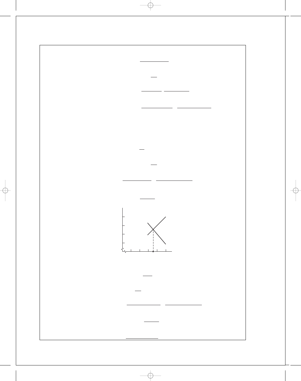
which is not 0.1 or less, therefore try averaging
(T
f
)
new
=
150°F
+ 119.3°F
2
= 134.6°F
budynas_SM_ch12.qxd 12/04/2006 15:24 Page 313
FIRST PAGES
314
Solutions Manual • Instructor’s Solution Manual to Accompany Mechanical Engineering Design
Proceed with additional trials
Trial
New
T
f
µ
S
T
T
a
v
T
f
150.0
2.421
0.0921
18.5
119.3
134.6
134.6
3.453
0.1310
23.1
121.5
128.1
128.1
4.070
0.1550
25.8
122.9
125.5
125.5
4.255
0.1650
27.0
123.5
124.5
124.5
4.471
0.1700
27.5
123.8
124.1
124.1
4.515
0.1710
27.7
123.9
124.0
124.0
4.532
0.1720
27.8
123.7
123.9
Note that the convergence begins rapidly. There are ways to speed this, but at this point
they would only add complexity. Depending where you stop, you can enter the analysis.
(a)
µ = 4.541(10
−
6
) reyn,
S
= 0.1724
From Fig. 12-16:
h
o
c
= 0.482, h
o
= 0.482(0.002) = 0.000 964 in
From Fig. 12-17:
φ = 56° Ans.
(b) e
= c − h
o
= 0.002 − 0.000 964 = 0.001 04 in Ans.
(c) From Fig. 12-18:
f r
c
= 4.10,
f
= 4.10(0.002/1.25) = 0.006 56 Ans.
(d) T
= f Wr = 0.006 56(1200)(1.25) = 9.84 lbf · in
H
=
2
πT N
778(12)
=
2
π(9.84)(1120/60)
778(12)
= 0.124 Btu/s Ans.
(e) From Fig. 12-19:
Q
r cN l
= 4.16,
Q
= 4.16(1.25)(0.002)
1120
60
(2
.5)
= 0.485 in
3
/s
Ans
.
From Fig. 12-20:
Q
s
Q
= 0.6,
Q
s
= 0.6(0.485) = 0.291 in
3
/s
Ans
.
(f) From Fig. 12-21:
P
p
max
= 0.45,
p
max
=
1200
2
.5
2
(0
.45)
= 427 psi Ans.
φ
p
max
= 16° Ans.
(g)
φ
p
0
= 82° Ans.
(h) T
f
= 123.9°F Ans.
(i) T
s
+ T = 110°F + 27.8°F = 137.8°F Ans.
budynas_SM_ch12.qxd 12/04/2006 15:24 Page 314
FIRST PAGES
Chapter 12
315
12-13
Given: d
= 1.250 in, t
d
= 0.001in, b = 1.252 in, t
b
= 0.003in, l = 1.25 in, W = 250 lbf,
N
= 1750 rev/min, SAE 10 lubricant, sump temperature T
s
= 120°F.
Below is a partial tabular summary for comparison purposes.
c
min
c
c
max
0.001 in
0.002 in
0.003 in
T
f
132.2
125.8
124.0
T
24.3
11.5
7.96
T
max
144.3
131.5
128.0
µ
2.587
3.014
3.150
S
0.184
0.053 7
0.024 9
0.499
0.775 0
0.873
f r
c
4.317
1.881
1.243
Q
r cN
j
l
4.129
4.572
4.691
Q
s
Q
0.582
0.824
0.903
h
o
c
0.501
0.225
0.127
f
0.006 9
0.006
0.005 9
Q
0.094 1
0.208
0.321
Q
s
0.054 8
0.172
0.290
h
o
0.000 501
0.000 495
0.000 382
Note the variations on each line. There is not a bearing, but an ensemble of many bear-
ings, due to the random assembly of toleranced bushings and journals. Fortunately the
distribution is bounded; the extreme cases, c
min
and c
max
, coupled with c provide the
charactistic description for the designer. All assemblies must be satisfactory.
The designer does not specify a journal-bushing bearing, but an ensemble of bearings.
12-14
Computer programs will vary—Fortran based, MATLAB, spreadsheet, etc.
12-15
In a step-by-step fashion, we are building a skill for natural circulation bearings.
• Given the average film temperature, establish the bearing properties.
• Given a sump temperature, find the average film temperature, then establish the bearing
properties.
• Now we acknowledge the environmental temperature’s role in establishing the sump
temperature. Sec. 12-9 and Ex. 12-5 address this problem.
The task is to iteratively find the average film temperature, T
f
, which makes H
gen
and
H
loss
equal. The steps for determining c
min
are provided within Trial #1 through Trial #3
on the following page.
budynas_SM_ch12.qxd 12/04/2006 15:24 Page 315
FIRST PAGES
316
Solutions Manual • Instructor’s Solution Manual to Accompany Mechanical Engineering Design
Trial #1:
• Choose a value of T
f
.
• Find the corresponding viscosity.
• Find the Sommerfeld number.
• Find f r
/c, then
H
gen
=
2545
1050
W N c
f r
c
• Find Q
/(rcNl) and Q
s
/Q . From Eq. (12-15)
T =
0
.103P( f r/c)
(1
− 0.5Q
s
/Q)[Q/(rcN
j
l)]
H
loss
=
¯h
CR
A(T
f
− T
∞
)
1
+ α
• Display T
f
, S, H
gen
, H
loss
Trial #2:
Choose another T
f
, repeating above drill.
Trial #3:
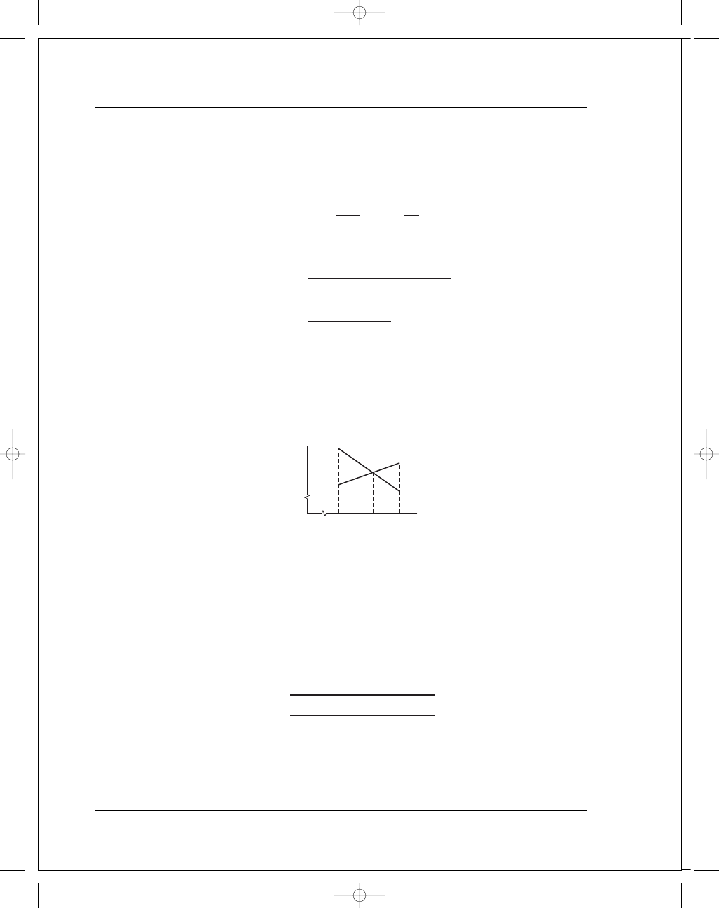
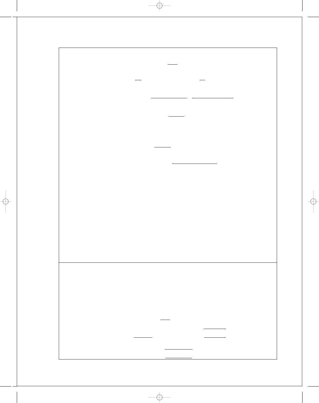
Plot the results of the first two trials.
Choose (T
f
)
3
from plot. Repeat the drill. Plot the results of Trial #3 on the above graph.
If you are not within 0.1°F, iterate again. Otherwise, stop, and find all the properties of
the bearing for the first clearance, c
min
. See if Trumpler conditions are satisfied, and if so,
analyze
¯c and c
max
.
The bearing ensemble in the current problem statement meets Trumpler’s criteria
(for n
d
= 2).
This adequacy assessment protocol can be used as a design tool by giving the students
additional possible bushing sizes.
b (in)
t
b
(in)
2.254
0.004
2.004
0.004
1.753
0.003
Otherwise, the design option includes reducing l
/d to save on the cost of journal machin-
ing and vender-supplied bushings.
H
H
gen
H
loss
, linear with T
f
(T
f
)
1
(T
f
)
3
(T
f
)
2
T
f
budynas_SM_ch12.qxd 12/04/2006 15:24 Page 316
FIRST PAGES
Chapter 12
317
12-16
Continue to build a skill with pressure-fed bearings, that of finding the average tempera-
ture of the fluid film. First examine the case for c
= c
min
Trial #1:
• Choose an initial T
f
.
• Find the viscosity.
• Find the Sommerfeld number.
• Find f r
/c, h
o
/c, and .
• From Eq. (12-24), find
T .
T
a
v
= T
s
+
T
2
• Display T
f
, S,
T, and T
a
v
.
Trial #2:
• Choose another T
f
. Repeat the drill, and display the second set of values for T
f
,
S,
T, and T
a
v
.
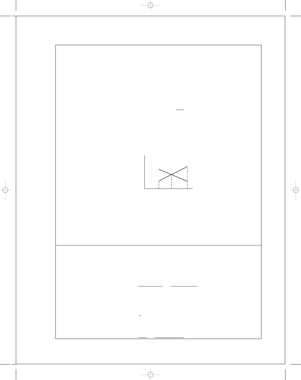
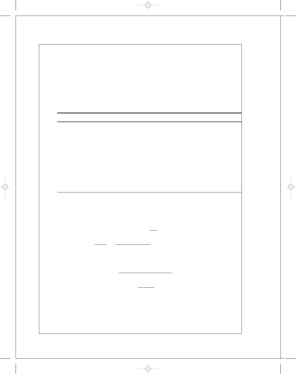
• Plot T
a
v
vs T
f
:
Trial #3:
Pick the third T
f
from the plot and repeat the procedure. If (T
f
)
3
and (T
a
v
)
3
differ by more
than 0
.1°F, plot the results for Trials #2 and #3 and try again. If they are within 0.1°F, de-
termine the bearing parameters, check the Trumpler criteria, and compare H
loss
with the
lubricant’s cooling capacity.
Repeat the entire procedure for c
= c
max
to assess the cooling capacity for the maxi-
mum radial clearance. Finally, examine c
= ¯c to characterize the ensemble of bearings.
12-17
An adequacy assessment associated with a design task is required. Trumpler’s criteria
will do.
d
= 50.00
+
0
.
00
−
0
.
05
mm,
b
= 50.084
+
0
.
010
−
0
.
000
mm
SAE 30, N
= 2880 rev/min or 48 rev/s, W = 10 kN
c
min
=
b
min
− d
max
2
=
50
.084 − 50
2
= 0.042 mm
r
= d/2 = 50/2 = 25 mm
r
/c = 25/0.042 = 595
l
=
1
2
(55
− 5) = 25 mm
l
/d = 25/50 = 0.5
p
=
W
4rl
=
10(10
6
)
4(0
.25)(0.25)
= 4000 kPa
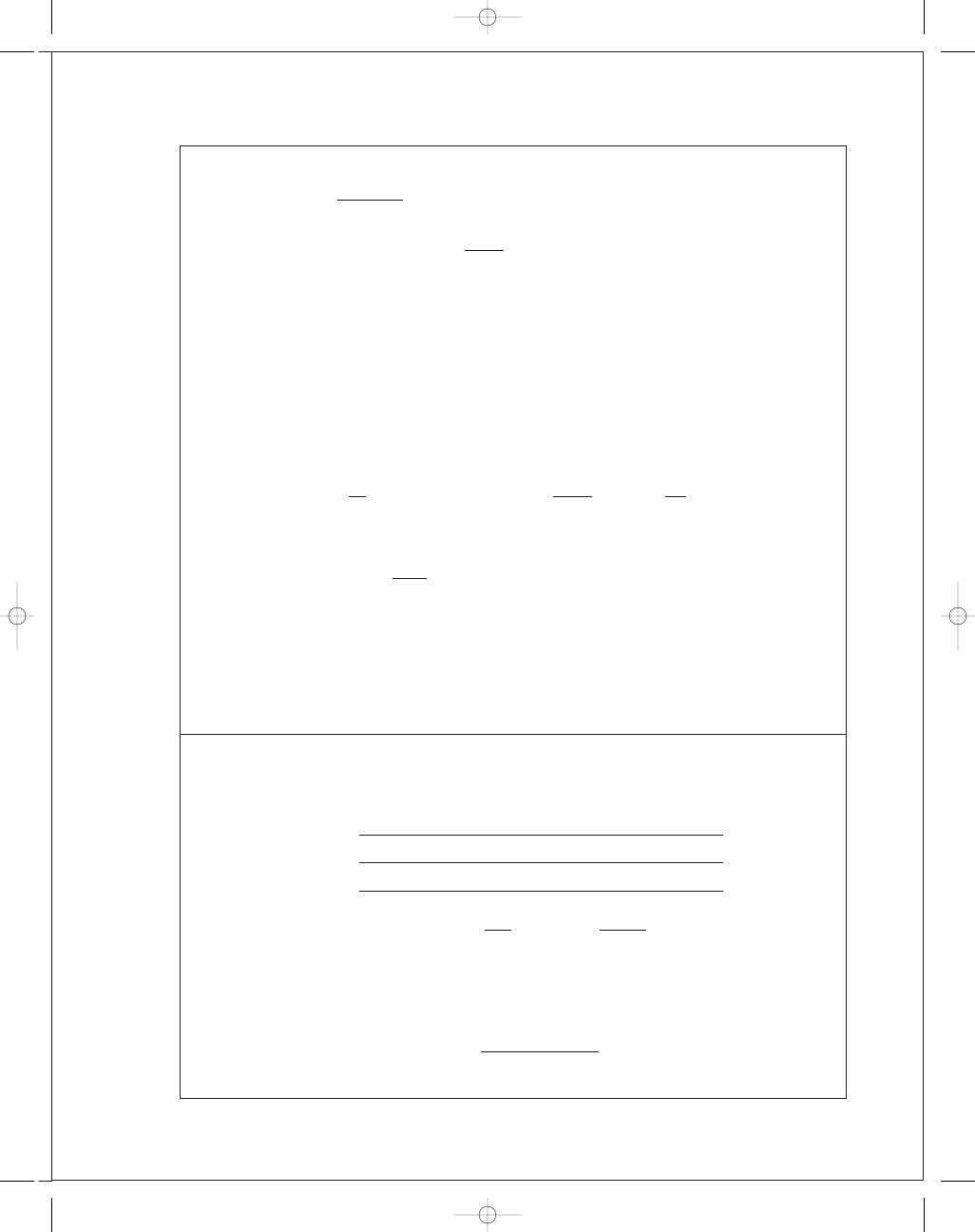
T
av
2
1
T
f
(T
f
)
1
(T
f
)
2
(T
f
)
3
T
av
⫽ T
f
budynas_SM_ch12.qxd 12/04/2006 15:24 Page 317
FIRST PAGES
318
Solutions Manual • Instructor’s Solution Manual to Accompany Mechanical Engineering Design
Trial #1: Choose (T
f
)
1
= 79°C. From Fig. 12-13, µ = 13 mPa · s.
S
= (595
2
)
13(10
−
3
)(48)
4000(10
3
)
= 0.055
From Figs. 12-18 and 12-16:
f r
c
= 2.3, = 0.85.
From Eq. (12-25),
T =
978(10
6
)
1
+ 1.5
2
( f r
/c)SW
2
p
s
r
4
=
978(10
6
)
1
+ 1.5(0.85)
2
2
.3(0.055)(10
2
)
200(25)
4
= 76.0°C
T
a
v
= T
s
+ T/2 = 55°C + (76°C/2) = 93°C
Trial #2: Choose (T
f
)
2
= 100°C. From Fig. 12-13, µ = 7 mPa · s.
S
= 0.055
7
13
= 0.0296
From Figs. 12-18 and 12-16:
f r
c
= 1.6, = 0.90
T =
978(10
6
)
1
+ 1.5(0.9)
2
1
.6(0.0296)(10
2
)
200(25)
4
= 26.8°C
T
a
v
= 55°C +
26
.8°C
2
= 68.4°C
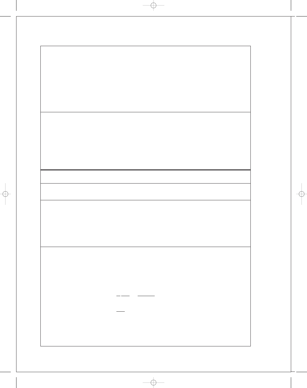
Trial #3: Thus, the plot gives (T
f
)
3
= 85°C. From Fig. 12-13, µ = 10.8 mPa · s.
S
= 0.055
10
.8
13
= 0.0457
From Figs. 12-18 and 12-16:
f r
c
= 2.2, = 0.875
T =
978(10
6
)
1
+ 1.5(0.875
2
)
2
.2(0.0457)(10
2
)
200(25)
4
= 58.6°C
T
a
v
= 55°C +
58
.6°C
2
= 84.3°C
Result is close. Choose
¯T
f
=
85°C
+ 84.3°C
2
= 84.7°C
100
T
av
T
f
60
70
80
90
100
(79
⬚C, 93⬚C)
(79
⬚C, 79⬚C)
85
⬚C
(100
⬚C, 68.4⬚C)
(100
⬚C, 100⬚C)
90
80
70
T
av
⫽ T
f
budynas_SM_ch12.qxd 12/04/2006 15:24 Page 318
FIRST PAGES
Chapter 12
319
Fig. 12-13:
µ = 10.8 MPa · s
S
= 0.055
10
.8
13
= 0.0457
f r
c
= 2.23, = 0.874,
h
o
c
= 0.13
T =
978(10
6
)
1
+ 1.5(0.874
2
)
2
.23(0.0457)(10
2
)
200(25
4
)
= 59.5°C
T
a
v
= 55°C +
59
.5°C
2
= 84.7°C
O.K.
From Eq. (12-22)
Q
s
= (1 + 1.5
2
)
πp
s
r c
3
3
µl
= [1 + 1.5(0.874
2
)]
π(200)(0.042
3
)(25)
3(10)(10
−
6
)(25)
= 3334 mm
3
/s
h
o
= 0.13(0.042) = 0.005 46 mm or 0.000 215 in
Trumpler:
h
o
= 0.0002 + 0.000 04(50/25.4)
= 0.000 279 in Not O.K.
T
max
= T
s
+ T = 55°C + 63.7°C = 118.7°C or 245.7°F O.K.
P
st
= 4000 kPa or 581 psi Not O.K.
n
= 1, as done Not O.K.
There is no point in proceeding further.
12-18
So far, we’ve performed elements of the design task. Now let’s do it more completely.
First, remember our viewpoint.
The values of the unilateral tolerances, t
b
and t
d
, reflect the routine capabilities of the
bushing vendor and the in-house capabilities. While the designer has to live with these,
his approach should not depend on them. They can be incorporated later.
First we shall find the minimum size of the journal which satisfies Trumpler’s con-
straint of P
st
≤ 300 psi.
P
st
=
W
2dl
≤ 300
W
2d
2
l
/d
≤ 300 ⇒ d ≥
W
600(l
/d)
d
min
=
900
2(300)(0
.5)
= 1.73 in
budynas_SM_ch12.qxd 12/04/2006 15:24 Page 319
FIRST PAGES
320
Solutions Manual • Instructor’s Solution Manual to Accompany Mechanical Engineering Design
In this problem we will take journal diameter as the nominal value and the bushing bore
as a variable. In the next problem, we will take the bushing bore as nominal and the jour-
nal diameter as free.
To determine where the constraints are, we will set t
b
= t
d
= 0, and thereby shrink
the design window to a point.
We set
d
= 2.000 in
b
= d + 2c
min
= d + 2c
n
d
= 2 (This makes Trumpler’s n
d
≤ 2 tight)
and construct a table.
c
b
d
¯T
f
*
T
max
h
o
P
st
T
max
n
fom
0.0010
2.0020
2
215.50
312.0
×
×
−5.74
0.0011
2.0022
2
206.75
293.0
×
−6.06
0.0012
2.0024
2
198.50
277.0
×
−6.37
0.0013
2.0026
2
191.40
262.8
×
−6.66
0.0014
2.0028
2
185.23
250.4
×
−6.94
0.0015
2.0030
2
179.80
239.6
×
−7.20
0.0016
2.0032
2
175.00
230.1
×
−7.45
0.0017
2.0034
2
171.13
220.3
×
−7.65
0.0018
2.0036
2
166.92
213.9
−7.91
0.0019
2.0038
2
163.50
206.9
−8.12
0.0020
2.0040
2
160.40
200.6
−8.32
*Sample calculation for the first entry of this column.
Iteration yields:
¯T
f
= 215.5°F
With ¯
T
f
= 215.5°F, from Table 12-1
µ = 0.0136(10
−
6
) exp[1271
.6/(215.5 + 95)] = 0.817(10
−
6
) reyn
N
= 3000/60 = 50 rev/s, P =
900
4
= 225 psi
S
=
1
0
.001
2
0
.817(10
−
6
)(50)
225
= 0.182
From Figs. 12-16 and 12-18:
= 0.7,
f r
/c = 5.5
Eq. (12–24):
T
F
=
0
.0123(5.5)(0.182)(900
2
)
[1
+ 1.5(0.7
2
)](30)(1
4
)
= 191.6°F
T
a
v
= 120°F +
191
.6°F
2
= 215.8°F .= 215.5°F
For the nominal 2-in bearing, the various clearances show that we have been in contact
with the recurving of (h
o
)
min
. The figure of merit (the parasitic friction torque plus the
pumping torque negated) is best at c
= 0.0018 in. For the nominal 2-in bearing, we will
place the top of the design window at c
min
= 0.002 in, and b = d + 2(0.002) = 2.004 in.
At this point, add the b and d unilateral tolerances:
d
= 2.000
+
0
.
000
−
0
.
001
in,
b
= 2.004
+
0
.
003
−
0
.
000
in
budynas_SM_ch12.qxd 12/04/2006 15:24 Page 320

FIRST PAGES
Chapter 12
321
Now we can check the performance at c
min
,
¯c, and c
max
. Of immediate interest is the fom
of the median clearance assembly,
−9.82, as compared to any other satisfactory bearing
ensemble.
If a nominal 1.875 in bearing is possible, construct another table with t
b
= 0 and
t
d
= 0.
c
b
d
¯T
f
T
max
h
o
P
st
T
max
fos
fom
0.0020
1.879
1.875
157.2
194.30
×
−7.36
0.0030
1.881
1.875
138.6
157.10
−8.64
0.0035
1.882
1.875
133.5
147.10
−9.05
0.0040
1.883
1.875
130.0
140.10
−9.32
0.0050
1.885
1.875
125.7
131.45
−9.59
0.0055
1.886
1.875
124.4
128.80
−9.63
0.0060
1.887
1.875
123.4
126.80
×
−9.64
The range of clearance is 0
.0030 < c < 0.0055 in. That is enough room to fit in our de-
sign window.
d
= 1.875
+
0
.
000
−
0
.
001
in,
b
= 1.881
+
0
.
003
−
0
.
000
in
The ensemble median assembly has fom
= −9.31.
We just had room to fit in a design window based upon the (h
o
)
min
constraint. Further
reduction in nominal diameter will preclude any smaller bearings. A table constructed for a
d
= 1.750 in journal will prove this.
We choose the nominal 1.875-in bearing ensemble because it has the largest figure
of merit.
Ans.
12-19
This is the same as Prob. 12-18 but uses design variables of nominal bushing bore b and
radial clearance c.
The approach is similar to that of Prob. 12-18 and the tables will change slightly. In the
table for a nominal b
= 1.875 in, note that at c = 0.003 the constraints are “loose.” Set
b
= 1.875 in
d
= 1.875 − 2(0.003) = 1.869 in
For the ensemble
b
= 1.875
+
0
.
003
−
0
.
001
,
d
= 1.869
+
0
.
000
−
0
.
001
Analyze at c
min
= 0.003, ¯c = 0.004 in and c
max
= 0.005 in
At c
min
= 0.003 in: ¯T
f
= 138.4°F, µ
= 3.160, S = 0.0297, H
loss
= 1035 Btu/h and the
Trumpler conditions are met.
At
¯c = 0.004 in: ¯T
f
= 130°F, µ
= 3.872, S = 0.0205, H
loss
= 1106 Btu/h, fom =
−9.246 and the Trumpler conditions are O.K.
At c
max
= 0.005 in:
¯T
f
= 125.68°F, µ
= 4.325 µreyn, S = 0.014 66, H
loss
=
1129 Btu/h and the Trumpler conditions are O.K.
The ensemble figure of merit is slightly better; this bearing is slightly smaller. The lubri-
cant cooler has sufficient capacity.
budynas_SM_ch12.qxd 12/04/2006 15:24 Page 321
FIRST PAGES
322
Solutions Manual • Instructor’s Solution Manual to Accompany Mechanical Engineering Design
12-20
From Table 12-1, Seireg and Dandage,
µ
0
= 0.0141(10
6
) reyn and b
= 1360.0
µ(µreyn) = 0.0141 exp[1360/(T + 95)]
(T in °F)
= 0.0141 exp[1360/(1.8C + 127)]
(C in °C)
µ(mPa · s) = 6.89(0.0141) exp[1360/(1.8C + 127)]
(C in °C)
For SAE 30 at 79°C
µ = 6.89(0.0141) exp{1360/[1.8(79) + 127]}
= 15.2 mPa · s Ans.
12-21
Originally
d
= 2.000
+
0
.
000
−
0
.
001
in,
b
= 2.005
+
0
.
003
−
0
.
000
in
Doubled,
d
= 4.000
+
0
.
000
−
0
.
002
in,
b
= 4.010
+
0
.
006
−
0
.
000
The radial load quadrupled to 3600 lbf when the analyses for parts (a) and (b) were carried
out. Some of the results are:
Trumpler
Part
¯c
µ
S
¯T
f
f r
/c
Q
s
h
o
/c
H
loss
h
o
h
o
f
(a)
0.007
3.416 0.0310 135.1 0.1612 6.56
0.1032 0.897 9898 0.000 722 0.000 360 0.005 67
(b)
0.0035 3.416 0.0310 135.1 0.1612 0.870 0.1032 0.897 1237 0.000 361 0.000 280 0.005 67
The side flow Q
s
differs because there is a c
3
term and consequently an 8-fold increase.
H
loss
is related by a 9898
/1237 or an 8-fold increase. The existing h
o
is related by a 2-fold
increase. Trumpler’s (h
o
)
min
is related by a 1.286-fold increase
fom
= −82.37
for double size
fom
= −10.297
for original size
}
an 8-fold increase for double-size
12-22
From Table 12-8: K
= 0.6(10
−
10
) in
3
· min/(lbf · ft · h). P = 500/[(1)(1)] = 500 psi,
V
= π DN/12 = π(1)(200)/12 = 52.4 ft/min
Tables 12-10 and 12-11:
f
1
= 1.8,
f
2
= 1
Table 12-12:
P V
max
= 46 700 psi · ft/min, P
max
= 3560 psi, V
max
= 100 ft/min
P
max
=
4
π
F
D L
=
4(500)
π(1)(1)
= 637 psi < 3560 psi O.K.
P
=
F
D L
= 500 psi
V
= 52.4 ft/min
P V
= 500(52.4) = 26 200 psi · ft/min < 46 700 psi · ft/min O.K.
budynas_SM_ch12.qxd 12/04/2006 15:24 Page 322

FIRST PAGES
Chapter 12
323
Solving Eq. (12-32) for t
t
=
π DLw
4 f
1
f
2
K V F
=
π(1)(1)(0.005)
4(1
.8)(1)(0.6)(10
−
10
)(52
.4)(500)
= 1388 h = 83 270 min
Cycles
= Nt = 200(83 270) = 16.7 rev Ans.
12-23
Estimate bushing length with f
1
= f
2
= 1, and K = 0.6(10
−
10
) in
3
· min/(lbf · ft · h)
Eq. (12-32):
L
=
1(1)(0
.6)(10
−
10
)(2)(100)(400)(1000)
3(0
.002)
= 0.80 in
From Eq. (12-38), with f
s
= 0.03 from Table 12-9 applying n
d
= 2 to F
and ¯h
CR
= 2.7 Btu/(h · ft
2
· °F)
L .
=
720(0
.03)(2)(100)(400)
778(2
.7)(300 − 70)
= 3.58 in
0
.80 ≤ L ≤ 3.58 in
Trial 1: Let L
= 1 in, D = 1 in
P
max
=
4(2)(100)
π(1)(1)
= 255 psi < 3560 psi O.K.
P
=
2(100)
1(1)
= 200 psi
V
=
π(1)(400)
12
= 104.7 ft/min > 100 ft/min Not O.K.
Trial 2: Try D
= 7/8 in, L = 1 in
P
max
=
4(2)(100)
π(7/8)(1)
= 291 psi < 3560 psi O.K.
P
=
2(100)
7
/8(1)
= 229 psi
V
=
π(7/8)(400)
12
= 91.6 ft/min < 100 ft/min
O.K .
P V
= 229(91.6) = 20 976 psi · ft/min < 46 700 psi · ft/min O.K.
⇒
f
1
= 1.3 + (1.8 − 1.3)
91
.6 − 33
100
− 33
= 1.74
L
= 0.80(1.74) = 1.39 in
V
f
1
33
1.3
91.6
f
1
100
1.8
budynas_SM_ch12.qxd 12/04/2006 15:24 Page 323

FIRST PAGES
324
Solutions Manual • Instructor’s Solution Manual to Accompany Mechanical Engineering Design
Trial 3: Try D
= 7/8 in, L = 1.5 in
P
max
=
4(2)(100)
π(7/8)(1.5)
= 194 psi < 3560 psi O.K.
P
=
2(100)
7
/8(1.5)
= 152 psi, V = 91.6 ft/min
P V
= 152(91.6) = 13 923 psi · ft/min < 46 700 psi · ft/min O.K.
D
= 7/8 in, L = 1.5 in
is acceptable
Ans.
Suggestion: Try smaller sizes.
budynas_SM_ch12.qxd 12/04/2006 15:24 Page 324
Wyszukiwarka
Podobne podstrony:
budynas SM ch01
budynas SM ch15
budynas SM ch16
budynas SM ch14
budynas SM ch05
budynas SM ch20
budynas SM ch09
budynas SM ch03
budynas SM ch10
budynas SM ch08
budynas SM ch11
budynas SM ch07
budynas SM ch04
budynas SM ch13
budynas SM ch02
budynas SM ch17
budynas SM ch06
więcej podobnych podstron