
Declaration of conformity and CE mark
This device meets the requirements of the following EC directive R&TTE 6/1999/EG:
»Directive 1999/5/EC of the European Parliament and of the Council of 9 March 1999 on radio equip-
ment and telecommunications terminal equipment and the mutual recognition of their conformity«.
You can also request this EC declaration of conformity at the following Internet URL: http://www.funkwerk-ec.com.
The waste container symbol with the “X” through it on the device indicates that the device must be
disposed of separately from normal domestic waste at an appropriate waste disposal facility at the end
of its useful service life.
© 2007 Funkwerk Enterprise Communications GmbH - All rights reserved.
Reprinting of this document, even excerpts, is permitted only with the express consent of the publisher and with pre-
cise source information, regardless of the media used (mechanical or electronic).
Function descriptions included in this documentation which refer to software products of other manufacturers are
based on the software used and valid at the date the documentation was prepared or published. The product and
company names used in this documentation may be protected by trademarks.
2

Table of contents
I

II

Router
The router module provides features for linking a PC to a LAN (Local area network) and enables high speed internet
access using xDSL or ISDN. Required safety is provided by an implemented firewall in conjunction with NAT (net-
work adress translation). The functions DHCP server and DNS proxy ensure that the scope of configuration, both for
your router system and your PC, is kept to a minimum . Internet access for all of the PCs connected to the router is
provided via one single connection (SUA - single user account).
Router of the ICT PABX system
What is a router?
A router allows LAN clients (computers, PC within a network) of one network (LAN) to obtain access to a different
network, for example the Internet. Access to the Internet is made available by various Internet service providers
(ISP).
In this process, the router searches for a path on which data can be exchanged between the LAN clients in the local
network and the Internet. Linking to the Internet can be carried out via an xDSL and / or an ISDN connection.
Router of the PABX system
The PABX system router is equipped with a WAN/xDSL and a LAN port. The router is connected to another network,
for example the Internet, via the WAN/xDSL port. You can hook up a DSL or cable model for connection to the
Internet.
The WAN-connection is an Ethernet-based port (10BaseT, 10MBit/s, half- duplex).
The LAN port is for your local network. Here, you can directly connect up a PC equipped with built-in network card.
If you wish to network several PCs you can accomplish this using an additional hUB / switch.
The LAN-connection is an Autosensing Fast Ethernet port. It sets itself automatically (from 10 Mbit/s half-duplex up
to 100 Mbit/s full duplex) to the maximum data transfer rate of the remote location (PC).
These PCs are also part of your local network and can, for example, exchange files or take advantage of the Internet
connections via the router. All LAN clients that are linked are integrated into the local network via the TCP/IP proto-
col.
Further PCs can be linked to your network via RAS. Here, the IP address is always assigned by the router, even when
the DHCP server is de-activated. Under “Address assignment” in the configuration program you can de-activate the
DHCP server and input the starting address for RAS. The following 4 IP addresses are then automatically reserved for
RAS.
Using the Remote Access Server (RAS) a field representative, for example, can call into the local network from an ex-
ternal location and then via the local network access the Internet. Access from an external location is only possible via
an ISDN connection. External access is provided with user-name and password protection. If the call is made from an
external location only, the phone number can also be monitored as an added protection feature. Note that this access
portal is not protected by a firewall!
Which Internet connections are supported?
You can set up a connection to the Internet with your router as follows:
·
Dial-up connections over ISDN (using PPP protocol, with one or two ISDN B channels, i. e. at 64
kbit/s or 128 kbit/s).
These types of connections require access data with the number to be dialed, the user name and
password and, in some cases, other information such as the IP address of the name server and any
information about the data compression method that is used (VJH).
·
Using xDSL (for example ADSL - T-DSL) in conjunction with a DSL modem that is compatible
with your ISP via PPPoE.
These connections require your user name and password as access data.
Router of the ICT PABX system
Router
1

·
Using xDSL (for example: B: SDSL) in conjunction with a DSL modem that is compatible with
your ISP with a set, public IP address. These connections require the public IP address that you
have been assigned, the IP address of the next gateway (next hop) and the IP address for the name
server of your provider.
The ISP that you wish to use for your Internet connections is set in the configuration of the router. You can configure
up to 10 ISPs. You can then define further settings for each ISP, such as user name, password, phone number, etc..
You can also define whether the connection to the Internet is to be set up automatically (default setting) and that the
next ISP in your list is to be selected once the connection has been established (fall-back).
When the PABX system router receives the command to establish an Internet connection this connection is set up
using the first ISP in your list. If the connection is set up successfully all of the clients in your network can access the
Internet. If the Internet connection is no longer needed (inactivity) it is terminated after a defined time (Short Hold).
If an Internet connection can not be set up using the selected ISP an attempt is made to establish the connection using
the next ISP in your list (fall-back).
When an Internet connection is terminated, the first ISP in the list is used when the next connection attempt is ini-
tially carried out.
Hinweis:
If “hubs” are installed in your network, for example, or if a connection to the Internet still exists, data packets may
continue to be sent to the router and the connection can not be terminated.
System telephones
You can configure a function key on the elmeg CS410 system telephone for monitoring router functions. The LED for
the function key then indicates the status of the router connection (none, connection via ISDN, connection via
WAN/xDSL). A new Internet connection can then be set up, or an existing connection terminated, just by pressing
the function key. Authorization for setting up or terminating router connections is managed by the PABX system.
Router
Router of the ICT PABX system
2

Default settings of the router
Default setting functions of the router
·
DHCP server, DNS server, DNS proxy active
·
Packet Filter Firewall
Default IP addresses for the local area network
The factory settings are already sufficient for using the router to access the Internet from your local network. You
have to define (when configuring the router) the Internet service provider that you wish to use.
The IP addresses for your local area network are then distributed as follows:
192.168.1.1 to
192.168.1.49
Freely assignable IP addresses as for example for LAN
clients with a fixed IP address
192.168.1.50 to
192.168.1.69
IP addresses that are allocated to corresponding LAN
clients by the router. (Number of DHCP clients: 20)
192.168.1.70 to192
192.168.1.80
Reserved IP-addresses (4) RAS. These addresses must
always remain reserved and may not be assigned as set IP addresses.
192.168.1.81 to
192.168.1.249
Freely assignable IP addresses as for example for LAN
clients with a fixed IP address
192.168.1.250
IP address for the PABX
192.168.1.251
to192
192.168.1.254
Freely assignable IP addresses as for example for LAN
clients with a fixed IP address
Hinweis:
Please note that each IP address can only be assigned once. The first and last IP address for a network may not be as-
signed to LAN clients. In this example: 192.168.1.0 and 192.168.1.255.
Example for the hint:
255.255.255.0
Subnet mask for all components on the network
(PABX, LAN clients,.. . )
192.168.1.250
Gateway IP address (router)
192.168.1.250
IP address for the DNS server (router). The PABX
system also acts as a DNS proxy in place of the ISP’s DNS server.
What are IP addresses and subnetwork masks?
With the initial settings IP addresses and subnetwork masks are already set for the PABX system router. Both of these
values are each 4 bytes in length.
IP address:
192.168.1.250
Subnet mask:
255.255.255.0
The IP address is an address that is reserved for private local networks.
The subnetwork defines that this is a Class C network in which up to 254 LAN clients can be linked. Using the
subnetwork mask an IP address can be divided into the network address and the host address (address of the PC).
Default settings of the router
Router
3

Example for the router:
Router
IP address:
192.168.1.250
IP netmask for the
router:
255.255.255.0
Network part of the
IP addresses:
192.168.1.xxx
Host part of the address:
x.x.x.250
First usable
IP address:
192.168.1.1 (netmask: 255.255.255.0)
Last usable
IP address:
192. 168. 1. 254 (netmask: 255.255.255.0)
You can assign the available IP addresses to the individual LAN clients manually, or have them assigned by the router
through DHCP. No IP address may be used simultaneously by more than one client however. With regard to the ex-
ample given above this means that the address 192.168.1.250 may not be allocated again, as it is already being used by
the router.
The network part of the IP address may not be changed, as otherwise the LAN clients would not all be located within
the same IP network. A PC with the IP address 192.168.2. 1 is located in a different network. A PC from the router net
would not be able to locate this other PC if it is not within its own network.
In addition, the same subnetwork mask must also be entered at all LAN clients located within the same network.
Router
Default settings of the router
4

Router functions
Automatic access to the Internet, Fallback
Several ISPs (ISP – Internet Service Provider) can be set up in the PABX. Connectivity to the Internet is provided via
the WAN port (e.g. DSL port), or via an ISDN port. If required, connection to the Internet can be set up automatically.
If your selected ISP is not available, the next ISP in the list will be selected automatically.
Short Hold
Short Hold means that the router terminates the Internet connection automatically after a configurable time period
when there is no exchange of data from/to the Internet (inactivity). You can set this time separately for each ISP that
you have configured.
This can result in increased connection costs with frequent, short excursions into the Internet, for example for pick-
ing up e-mails, as the connection is always maintained for the duration of the set holding time.
Dynamic ISDN
Higher data transfer rates can also be achieved for Internet access via the ISDN connection by bundling the two B
channels for the connection. If an Internet connection with channel bundling is active and a B channel is needed for
telephony or fax messages, one B channel is disconnected from the Internet connection. On completion of the voice
connection the B channel reverts automatically to use for the Internet connection.
This function is supported as long as you have only one external ISDN connection configured.
Dialer protection
Dialer protection monitors all external “Data links” for the PABX system. This function provides protection against
inadvertent dialing of extra pay numbers, in Germany so-called “190" numbers. Data links are set up only to enabled
numbers. The ISP numbers are enabled automatically and do not have to be entered in the list of unrestricted data
numbers.
DHCP server
PCs can be provided with a major portion of the configuration required for LAN and Internet access via the DHCP
(Dynamic Host Configuration Protocol). The DHCP server integrated into the PABX is capable of supplying corre-
sponding configurations to several PCs (LAN-clients). IP addresses are dynamically allocated to the clients. This
mode is recommended to dispense with the complicated, manual configuration of the IP addresses for the PC that
would otherwise be required.
DNS server
The DNS server (Domain Name Server) has the task of establishing names within a network. In this process the IP ad-
dresses of the PCs (e.g. LAN clients) are transformed into names. You must therefore know the name, and not the IP
address, of a PC that you wish to access, or are searching for. The DNS server can also establish names that are not in-
cluded in the local network.
DNS-Proxy
A proxy assumes a surrogate function for the local network (LAN) in a different / external network. Here, the DNS
proxy accepts the name queries from the LAN client and submits them to the external network, e.g. Internet, as its
own queries. The proxy then takes the response from the external network and forwards it to the LAN client that
placed the original query. In addition, the result from the query is stored for a defined time (configurable) to answer
any subsequent queries of the same type.
Dynamic DNS
Using Dynamic DNS you can also offer your own Internet services (e.g. WEB, FTP or e-mail servers). Usually you
must have a fixed leased line or a fixed IP address for this so that you can always be reached at the same URL (for ex-
ample: www.funkwerk-ec.com).
You are assigned a new IP address by the ISP each time you dial in to the Internet however. Using Dynamic DNS you
can link this automatic (dynamic) IP address with a set name. The router will then inform your Dynamic DNS service
provider (e.g. www.dyndns.org) automatically of the new IP address. Internet enquiries for your Web services are
then automatically forwarded to your dynamic IP address via your service provider.
Using Dynamic DNS
Router functions
Router
5

·
Configure an Internet address (URL) at a Dynamic DNS service provider. For example, at
“www.dyndns.org” configure the address “www.my-homepage.dyndns.org”.
·
Configure the LAN client of the network in which you wish to offer your Web services with a set
IP address. For example, let’s say we want to configure a Web server with the IP address
192.168.1.200.
·
Activate the Dynamic DNS function in the router and enter the Internet address (URL) for your
Dynamic DNS provider (in the example here www.dyndns.org).
Add the necessary filters in the firewall to allow the PC with the Web services to be reached from
an external location.
- Configure port mapping for Port 80 (HTTP protocol) to IP address 192.168.1.200.
- Configure the filters that permit incoming and outgoing WAN connections at Port 80.
·
The router will automatically inform your Dynamic DNS provider of your current dynamic IP ad-
dress each time a connection is set up with the Internet. The information about the IP address is
transferred after setting up a new Internet connection, as well as during an ongoing Internet con-
nection.
·
A PC in the Internet enters the address (URL) “www.my-homepage.dyndns.org”. In this way it
reaches your Dynamic DNS service provider. Your service provider reroutes the connection to
your current dynamic IP address.
·
Any incoming connection is handled in accordance with the configured filters. In the example gi-
ven here the incoming WAN connection at port 80 is forwarded to the LAN client with the IP ad-
dress 192.168.1.200. The accessible Internet sites of your Web server are displayed at the outside
PC.
NAT
NAT (Network Adress Translation) protects the connected LAN-clients against attacks from the Internet. Here, the
internal IP addresses are not passed on to the Internet. The router carries out the transfer to the Internet and distrib-
utes the incoming data packets in the internal system. This only requires one external IP address. The internal IP ad-
dresses are protected from attacks from outside. The internal IP addresses can not be targeted by hackers, as these IP
addresses are non-accessible.
Packet Filter Firewall
The integrated filter firewall packet also provides you with enhanced security against attacks from the Internet. A
firewall acts as a logical wall for data packets between the Internet and the LAN which has »holes« for certain packets
(firewall rules, also known as filters), allowing these packets to pass through the wall. The filters are described by
rules whose configuration requires expert knowledge about the TCP/IP protocol family. The firewall of the router
can be easily configured using a Filter Wizard in which you need to indicate (in plain text) whether you wish to allow
defined applications access to the Internet.
Portmapping
You wish to access your PC from an external location via Internet. Normally, access via the firewall should be prohib-
ited. When you use port mapping, access to a router port that you have enabled is permitted from an external loca-
tion. The router then forwards the access request to the defined port of the PC in the network. A fixed IP address must
be assigned to this PC. When the PC returns data packets the IP address and port number of the PC are replaced by
the router with the number for the port mapping port and the router IP. For “outsiders” on the Internet it then ap-
pears as though there is only one connection to the router.
Hinweis:
Please note that when you use port mapping the firewall for the ports enabled for this function is ineffective. The
target PC in your LAN may then be susceptible to any potential attacks.
Port mapping is practical when you wish to run a game server on your own, for example.
·
You can make this server accessible via the Internet to other users.
Router
Router functions
6

·
Or, if you require certain peer-to-peer file sharing software that provides greater download band-
width.
·
When the corresponding PC in your LAN is to be accessible from the Internet (not possible in the
standard configuration with NAT). In this case, certain UDP and TCP ports must be rerouted to a
PC in the LAN.
RAS-Server
Using the Remote Access Server (RAS) a field representative, for example, can call into the local network from an ex-
ternal location and then via the local network access the Internet. Access from an external location is only possible via
an ISDN connection.
External access is provided with user-name and password protection. If the call is made from an external location
only, the phone number can also be monitored as an added protection feature. Access can be enabled for several us-
ers. A Windows enable (access to computer, files or printers) and Internet enable can also be configured for each
user.
Hinweis:
Note that this access portal is not protected by the firewall!
A PC that dials into the local network via RAS is automatically assigned an IP address by the integrated DHCP server.
LAN-CAPI
The package includes a program called »CAPI for LANs« for use in your network. This software can be installed on
any PC in the network. This gives you the possibility of running your CAPI application from a central location via an
interface, i. e. the PABX system. There is no ISDN card required for the PCs. Please note that software used for the
CAPI application may require certain license agreements with the software manufacturer. The programme »CAPI in
LAN« does not require a license to run.
LAN-TAPI
The package includes a program called »TAPI for LANs« for use in your network. This software can be installed on
any PC in the network. This gives you the possibility of running your TAPI application from a central location via an
interface, i. e. the PABX system. There is no ISDN card required for the PCs. Please note that software used for the
TAPI application may require certain license agreements with the software manufacturer. The programme »TAPI in
LAN« does not require a license to run.
Router functions
Router
7

Configuration of the Internet Service Provider (ISP)
An Internet Service Provider provides you with an »entrance portal« to the Internet. A distinction is made between
ISPs with whom you have a contract (for example T-Online) and Internet-by-call providers that bill you through
your phone bill (for example Freenet).
The type of access is independent of the tariff charges; this can be based on actual time, volume or be a flat rate.
You can set up a connection to the Internet with your router as follows:
·
Dial-up connections via ISDN (using PPP protocol, with one or two ISDN B channels, i. e. at 64
kBit/s or 128 kBit/s).
These types of connections require access data with the number to be dialed, the user name and
password and, in some cases, other information such as the IP address of the name server and any
information about the data compression method that is used (VJH
·
Via xDSL (for example ADSL - T-DSL) in conjunction with a DSL modem compatible with your
ISP using PPPoE.
These connections require your user name and password as access data.
·
Using xDSL (for example: B: SDSL) in conjunction with a DSL modem that is compatible with
your ISP with a set, public IP address. You must have the public IP addresses that you have been
assigned, the IP address for the next gateway (next hop) and the IP address of the name server of
your provider for these connections.
Internet-by-Call
The Professional Configurator of the PABX system contains a list of Internet-by-call ISPs from which you can select a
provider. The advantage here is that you can set up an Internet connection immediately without first having to agree
to a contract. (The requisite access data are already contained in the configuration software for the Internet-by-call
ISPs that are listed). You can change this configuration when you decide to conclude a contract with a provider for
example (at present required for all DSL providers).B:
·
Fallback configuration for several ISPs »Internet always works«
·
You can configure more than one IPS in your PABX system.
·
You have one DSL connection that is not always available.
Here, you can configure the router so that it automatically attempts to set up an Internet connec-
tion via DSL. If this attempt is unsuccessful Internet connection over ISDN can be programmed
using a different ISP.
·
You are using a provider that is not always available (some Internet-by-call providers have very
reasonable rates, but their access nodes are overloaded due to heavy traffic during peak times).
Here you can simply configure several Internet-by-call providers. The router will automatically
attempt to set up a connection with one of the configured ISPs.
You can easily change the order of the ISPs with which the Internet connection is to be set up (»Fallback order« down
/ up). You can also set the number of and intervals between these attempts at setting up an Internet connection for
each ISP that has been configured. When the waiting period between the attempts expires and when the configured
number of actual attempts is reached and no connection has been established, the next ISP in the list is selected.
Connection to the Internet is always set up automatically by the router when a data packet is to be sent to the Internet.
This occurs automatically when you enter http://www. funkwerk-ec.com in your browser for example.
Hinweis:
Billing of the costs is made through the telephone bill from your network provider.
Discontinuing an Internet connection
Manual termination of a connection
Click on the symbol for the »ControlCenter« in the task bar and select »Terminate connection to provider«.
Router
Configuration of the Internet Service Provider (ISP)
8

Automatic termination of a connection
After a set time (which can be defined), during which there is no data traffic to the Internet, the connection is termi-
nated automatically. You can activate/de-activate this function in the configuration.
·
If you set the parameter »Terminate on inactivity« too high, this may result is considerable costs
for time-based charges.
·
If “hubs” are installed in your network, for example, or if a connection to the Internet still exists,
data packets may continue to be sent to the router and the connection can not be terminated.
·
If the router determines that there is incoming data from the Internet the connection will not be
terminated automatically when the set inactivity time expires. This can result in considerable
costs, even though you are not actually using the Internet connection. This can occur, for exam-
ple, when a port scan is conducted toward the router (frequently the advance stages of a hacker
attack). A further possibility is that peer-to-peer file sharing software has been run using the IP
address that was assigned automatically to the router by the ISP. In this case, queries for
downloading files from the Internet to the IP address currently being used for your Internet con-
nection can continue to arrive over an extended period of time. Although these queries can not be
responded to they can not be technically prevented either.
Hinweis:
If you have a flat rate charge with your ISP you can set the parameter »Terminate on inactivity« to. In this case the
router will not automatically terminate the Internet connection, but will re-establish the connection if required (for
example B: after being disconnected by the ISP). If you have configured several ISPs, make sure that you make this
setting for the correct ISP entry in the ISP list!
Using a fall-back
Let’s assume you have a DSL connection with the Deutsche Telekom AG (German Telecom) and have selected T-On-
line as your ISP.
You have configured three ISPs:
·
1. Internet access via T-DSL (T-Online). The router will use the PPPoE protocol at the WAN port.
Enter your access data (mark the ISP in the list, field »Edit«, field »Access data for T-Online«)
·
2. Internet access via ISDN (T-Online). The router uses an ISDN dial-up connection (and the PPP
protocol). Enter the same access data (mark the ISP in the list, field »Edit«, field »Access data for
T-Online«).
·
3. Internet access using an Internet-by-call provider. The router uses an ISDN dial-up connection
(and the PPP protocol). When you select an Internet-by-call provider from the defined list, the
corresponding parameters are already configured (»Access data«, »Number«).
If there is a disturbance with the DSL connection, the router will, after a configured time period keep attempting to
set up the Internet connection for the number of times configured in the field »Number of connection attempts. You
can activate/de-activate this function in the configuration. You can set the intervals between the attempts using the
parameter »Time between attempts« in the configuration item Network Internet. You can set the number of at-
tempts and the interval between these attempts separately for each ISP that has been configured.
After that, the router will use the next ISP configured in the list for attempting to set up a connection.
If the connection is disrupted and an attempt is to be made later to re-establish the connection, this cycle is restarted
beginning with the first entry in the list.
Configuration of the Internet Service Provider (ISP)
Router
9

Configuring DHCP server and IP address allocation
After you connect a PC IP addresses must be assigned. When doing this you must ensure that the IP addresses as-
signed to the PCs and the router are in the same IP network. This also applies when you wish to use common re-
sources within a LAN with several PCs (for example, enabled directories, network drives, network printers). All PCs
located within the network require an IP address.
You can define in the system configuration the number of possible LAN clients via DHCP and the first IP address that
is to be assigned via DHCP. The required number of IP addresses is assigned to the PCs (DHCP clients) in ascending
order. Eleven additional IP addresses for the DHCP server are always reserved for PCs that are integrated through
RAS (remote access server) into the local network. If the integrated DHCP server is activated the 11 IP addresses
which come after the configured DHCP address range are used for RAS clients. When the DHCP servers are de-acti-
vated the 11 IP addresses that come after the set DHCP start address will be used for RAS clients.
If you select a configuration in which some PC receive their IP addresses via DHCP, while others use set (manually
configured) IP addresses, the following criteria must be fulfilled:
·
All IP addresses must belong to the same IP network, meaning that the network part of the IP ad-
dress (and with it, the netmask) must be identical. Example:
·
Router IP address:
192.168.1.250
·
IP netmask for the router:
255.255.255.0
·
Network part of the IP addresses:
192.168.1.xxx
·
First usable IP address:
192.168.1.1
(netmask:
255.255.255.0)
·
Last usable IP address:
192.168.1.254
(netmask:
255.255.255.0)
·
First IP-address via DHCP:
192.168.1.50 (as per configuration)
·
Last IP address through DHCP:
192.168.1.69 (by configuration)
·
Number of IP addresses by
DHCP: 20
·
IP addresses for RAS per DHCP (4 reserved)
first IP-address:
192.168.1.70
last IP-address:
192.168.1.73
·
One IP address may not be used by more than one client at any one time; with regard to the exam-
ple given above this means that the IP addresses 192.168.1.2 to 192.168.1.49 and 192.168.1.74 to
192.169.1.249 and 192.168.1.251 to 192.169.1.254 can be used for PCs which have manually con-
figured IP addresses.
Hinweis:
Further configurable parameters for the DHCP server that you can select allow you the option of also using the
DHCP server in the existing LAN environment.
Default TTL
If you can not reach certain sites in the Internet (a »ping« is answered with the message »destination unreachable«) it
may be meaningful to increase the parameter »TTL« (default is 64) and specify that all PCs configured via DHCP to be
re-assigned configuration from the DHCP server (or simply restart your PC).
MTU
Router
Configuring DHCP server and IP address allocation
10

The parameter »MTU« is used for defining the data packet size used in the LAN. Only packets with a maximum »pay-
load« of 1452 bytes can be transported via a DSL Internet portal (when the PPPoE protocol is used, for example with
T-Online. Packets in the router should not be split up first and reply packets not re-assembled. It is therefore expedi-
ent to use an »MTU« of 1452 bytes to achieve the greatest possible data throughput rate for the DSL connection. This
may, however, result in the data transfer rate in the LAN being reduced slightly.
DHCP lease time
The lease time is the time (in seconds) for which a LAN client receives an assigned IP address before that address is
fetched and returned to the DHCP server address pool. A LAN client can extend the lease time automatically.
Default Gateway
You should enter 0. 0. 0. 0 (place holder for the PABX system IP address) as the »Default gateway« if Internet access it
to be provided via the PABX system.
Domain suffixes
You should only configure the parameters »Domain Names« and »DNS server« when you are operating a DNS server
within the LAN.
Netbios Name Servers
The parameter »Netbios Nameserver« is used for the name definition for Windows PCs when you use a WINS server
in the LAN. This parameter should only be configured when you operate a WINS server in the LAN.
Time Servers
The parameter »Time Servers« is used for announcing the IP address for the »Time leasee« when your PCs direct
(Windows XP, Linux) the NTP (Network Time Protocol).
DNS Servers
DNS queries from computers in the LAN are normally forwarded to one or more external DNS servers by the DNS
proxy. The addresses for the external DNS servers can be obtained dynamically, or can be permanently configured in
the router. Addresses can be input at three DNS servers to reduce online time.
Configuring DHCP server and IP address allocation
Router
11

Configurating the Packet Filter Firewall
When you use NAT, the PCs connected to the router are well protected against attacks from the Internet.
If you wish to have additional security you can also use the integrated package Filter Firewall. A firewall acts as a logi-
cal wall for data packets between the Internet and the LAN which has »holes« for certain packets (firewall rules, also
known as filters), allowing these packets to pass through the wall. In the initial status the firewall is configured such
that all data can pass through that are sent in the direction of the Internet.
Hinweis:
An exception to this rule is the »$I[]Netbios-Filter>Netbios-Filter«: This filter prevents the forwarding of Netbios
name queries from Windows PCs to the Internet. As the names of the Windows PCs within the LAN are not known
in the Internet, it is not meaningful to establish an Internet connection for forwarding the name query (this could
result in considerable costs, as these name queries occur frequently, meaning that the Internet connection would
practically never be terminated).
The filters are described by rules whose configuration requires expert knowledge about the TCP/IP protocol family.
The firewall of your router can be easily configured using a Filter Wizard in which you need to indicate (in plain text)
whether you wish to allow defined applications access to the Internet.
We recommend configuring the firewall filters with the aid of the Filter Wizard to ensure configuration(s) appropri-
ate for and compatible to the applications being used. These filters provide protection against data packets from the
Internet that may result in you being charged for certain connections. The function for the “Automatic connection
setup”, for example, may otherwise not always be ensured. A port scan from the Internet (usually the initial stage of a
hack attack) may sometimes occur; the router firewall then replies to this scan with »Reject packets«. But this may
nevertheless result in data traffic that prevents automatic setup of a connection.
Hinweis:
The filters available using the Filter Wizard have been implemented using the latest knowledge. We can, however,
provide no guarantee for the function of the filters. Use of a firewall should go hand in hand with use of virus scan-
ning software on all your PCs! Firewalls and virus scanners cover different areas of data security and are an ideal
compliment to one another, but can not replace one another.
User-defined filters for the router with packet filter firewalls can be configured under Network / Filters. To configure
self-defined filters click the button “New ...” or change an existing entry in the filter list by double clicking on that
item. An explanation of the filter function is given when you click on “Help”.
Basic information about firewall configuration
It is important that you have detailed knowledge about the IP protocol family before you begin configuring the
firewall. If your knowledge about this is not so in-depth we recommend using a filter wizard.
The firewall functions like a chain of rules through which each IP packet is routed. If a rule applies to a packet the ac-
tion associated with this rule will be executed (allow, deny or execute portmap). All rules are given in the list under
Network / Filters. Please note that for certain configurations the order of the filters can be of great significance for the
functioning of the firewall. Therefore, after you mark a filter rule you can define the order of the rules in the table us-
ing the buttons [up] and [down].
If no rule applies to the IP packet a super-ordinate, basic rule at the end of the chain decides on the action to be taken
(behavior by last filter rule).
This is why you must define the behavior.. .. .. for this super-ordinate rule at the beginning of the filter configuration.
You can choose between »Allow« or »Discard« for this.
Discarding of the packet is generally a safe procedure, as only those packets for which an explicit rule (i.e. deliberately
configured) exists are authorized in such a configuration.
When defining the filters it is essential to take into account that basically all packets are permitted at all LAN ports.
You therefore do not need to define filter rules for passing IP packets from the LAN to the router, nor for their »Re-
turn«.
Router
Configurating the Packet Filter Firewall
12

Four place holders are provided to achieve an abstraction when defining the filters:
LAN_ADDR
Represents the LAN address for the router, based on
the default configuration, i. e. 192.168.1.250 with the network mask
255.255.255.0 (192.168.1.250 / 24).
LAN_NET
This place holder represents all of the LAN addresses,
based on the default configuration, i.e. 192.168.1.0 with network mask
255.255.255.0 (192.168.1.0 / 24).
WAN_ADDR
This place holder represents the WAN address for the
router that is assigned dynamically by the ISP when PPoE or PPP is used.
Dynamic allocation allows an IP address to be assigned from the inventory of
your ISP for the WAN port each time a connection is set up to the Internet. The
WAN address can not be entered as an absolute value for filter configuration
when you are defining the configuration. PPPoE is required for T-DSL for
example; PPP is used for Internet connections with ISDN dial-in. If you have
been assigned a set public IP address by your provider for your Internet access,
this address will be used for WAN_ADDR.
The firewall is adapted automatically in accordance
with the defined rules after the IP address is assigned to the WAN port (or ISDN
channel).
WAN_NET
Represents all WAN addresses located in the same IP
subnetwork as the WAN port. This parameter is currently not used and will not
be significant for future software updates.
You can configure the following parameters:
Name of the filter
Each filter must be assigned a unique name. Select a
name for the filter that uniquely describes the function for that filter - this will
make it easier for you later if you wish to change any filters.
Action
The following options can be selected: allow, deny,
discard and portmap. When »allow« is selected, all packets which correspond to
the parameters of the associated filter can pass through. When »deny« is selected,
the corresponding IP packets are rejected and the sender of the packet is
informed. »discard« results in packets being discarded (refused) without the
sender being informed. The option »portmap« permits specific forwarding of
packets with TCP and UDP protocols to the IP address of a PC in the LAN.
TCP Flag
If a TCP connection is to be set up (for example for
downloading files), certain bit samples are set in the packets involved with this -
the TCP flags. The option »connection in progress« stands for the SYN flag; the
option »connection established« for the »Established flag«
Protocols
UDP, TCP, ICMP and »all protocols« can be selected as
protocols. The selection of the protocol can affect further options, as, for
example, there are no TCP flags available for UDP, or no port for ISM, while
there are certain types of protocols available however.
Interface
Here you can define the interfaces for the
correspondend filter. At present, the setting »WAN« is useful for most cases, as
all packets are allowed at internal interfaces with this setting.
Connection
Use this field to define the direction of the IP packet for
which the configured filter is valid. Possible parameters: in, out and in/out
(bi-directional).
Source address definition
Here you specify the source address for the IP packets
for which this filter is valid. Take into account any potential abstractions brought
about by place holders.
Target address definition
Here you specify the target address for the IP packets
for which this filter is valid. Take into account any potential abstractions brought
about by place holders.
Configurating the Packet Filter Firewall
Router
13

Warning message for port protocol association
A warning appears if you attempt to enter an unknown
name in the field for the TCP port. If this is bothersome you can suppress this
message by removing the corresponding check in the box.
Example of configuration for enabling the firewall for Web surfing.
First, set the response by the last filter rule to »discard«.
The IP packets for two services must be routed through the firewall in order that pages from the World Wide Web can
be displayed: DNS for establishing names and the »html data flow«. When you enter a URL in the Web browser, the
browser uses a DNS inquiry for transforming the plain-text name (for example www. Telekom. de) into an IP address
(in the example here 217. 160. 73. 88). After that, the browser establishes at least one connection to this IP address via
TCP/IP. This yields the following filter configuration:
The UDP and TCP protocol must be enabled for DNS (protocol name: domain) for the destination port 53 of any DNS
server from any non-privileged port; same applies for the return route.
Access to any destination addresses for port 80 must be possible for http requests for the TCP protocol via the WAN
interface from non-privileged ports. The return patch for reply packets must be enabled appropriately: From any
Internet IP addresses (0.0.0.0 / 0) from port 80 to non-privileged ports for the WAN address of the router.
Configuration example for a portmapping entry into the firewall for the ssh-protocol
The ssh protocol (secure shell) is used among other things for web server administration, or to implement VPN tun-
nels. Data can be transferred encrypted using the ssh protocol (not significant for configuration of the firewall how-
ever). Normally, port 22 of the TCP protocol is used. In the example shown here, the web server in your LAN has the
set, assigned IP address 192.168.1.42. Administration access should be provided for this web server in your LAN via
ssh from the Internet. Please note that you also require equivalent filters for Port 80 if the contents of the web server
are to be accessible from the Internet
You must generate three rules for the firewall based on this information with the default setting »Response by last fil-
ter rule à discard«:
ssh_MAP:
This filter routes incoming packets from any IP
addresses and non-privileged ports to the Internet-end IP address of the
telephone system router unit to the computer with the IP address 192.168.1.42;
Port 22 is retained.
ssh_WAN_in:
This filter permits passing of incoming packets from
any IP address and non-privileged ports to the Internet-end IP address of the
telephone system router unit.
ssh_WAN_out:
This filter permits outgoing packets from Port 22 to
pass through the WAN interface (i. e. the connection for the DSL modem or the
ISDN dial-up connection to the Internet) to any IP address and non-privileged
ports.
Filter name
TCP-Flag
Interface
Action
Protocoll
Con-nection Source IP
Source port
Target IP
Target port
Netbios-
block
none
WAN
discard
UDP
out
0.0.0.0/0
137-139
0.0.0.0/0
any
ssh_
portmap
none
WAN
portmap
TCP
in
0.0.0.0/0
22
192.168.1.4
2
22
ssh_WAN_i
n
none
WAN
allow
TCP
in
0.0.0.0/0
any
WAN_ADD
R
22
ssh_WAN_
out
none
WAN
allow
TCP
out
WAN_ADD
R
22
0.0.0.0/0
any
Attention!
Hinweis:
As a result, the PC in your LAN with the IP address 192.168.1.42 has no protection whatsoever from the firewall in
your telephone system at Port 22/TCP! You can restrict access options where required if access is to always be effec-
ted from an Internet connection with a set IP address (for example T-Interconnect). Here, any entries which con-
tain “0. 0. 0. 0/0" should be matched to the known IP addresses of the remote location (0. 0. 0. 0/0 is a global proxy
Router
Configurating the Packet Filter Firewall
14
address for all IP addresses).
If you wish to employ a combination of filters consisting of filters that have been generated using the Filter Wizard
and your own custom filters, or port map entries, be sure to check the order of the rules in the table (you can change
the order using the buttons »up« and »down«). The “Secure system” filter, which blocks all packets directed toward
so-called privileged ports, is offered in the Filter Wizard. In the example given here this filter would counteract the
configured functionality, as the ssh port (22) is a privileged port. We urgently recommend blocking all privileged
ports that are not needed; it may therefore be expedient to use the filter configured by the Filter Wizard that has been
appropriately adapted, or that is located at the appropriate position in the table.
Hinweis:
If you are not sure which ports must be routed to the LAN PC for certain applications, or for attaining defined user
privileges in exchange networks using port mapping by your telephone system router, enter the name of the appli-
cation and the terms »port« and »firewall« in an Internet search engine; configuration instructions can usually be
found quite easily in this manner. You can reroute one single port, or port ranges (for example 4661-4665) using a
port map rule.
Filter Wizard
The firewall is configured such that all data packets for which no explicit rule (filter) exists which would otherwise al-
low the packets to pass are rejected. This procedure makes the configuration of the firewall somewhat more compli-
cated, but significantly reduces the probability of “overseeing” the blocking of some packets to prevent them from
passing through the firewall.
Some filters contain rules for rejecting packets which would actually not be required for the selected basic configura-
tion of the firewall, because the firewall would reject any packets not enabled by the filters, based on the configuration
carried out by the Wizard. The rejection rules mentioned above are nevertheless retained to reject packets used in
certain attacks at the earliest possible stage to prevent the packets from passing through the entire chain of filter
rules; this enhances firewall performance in the event of a real attack.
Filter Wizard
Router
15

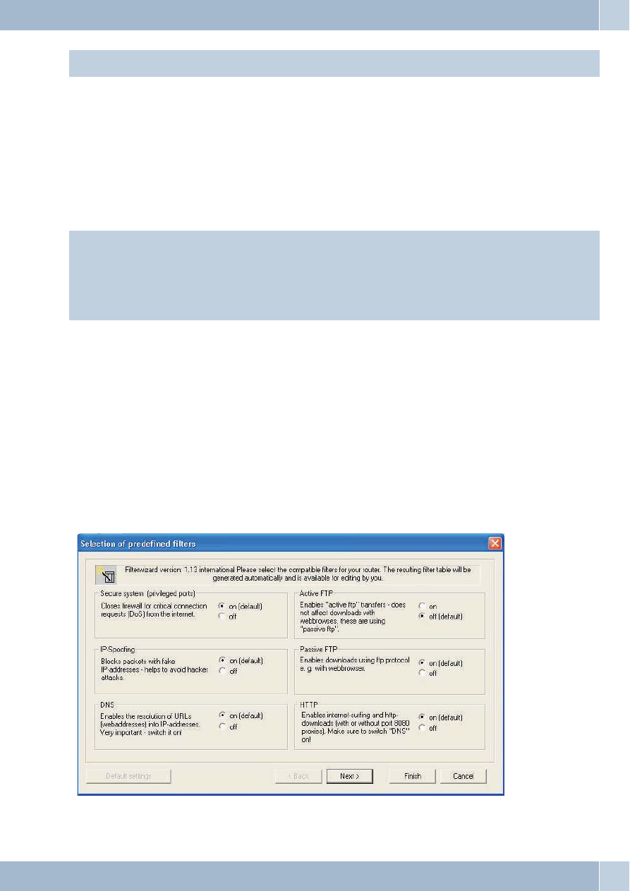
Example for predefined filters in the filter wizard
Help for the various filters contained in the Filter Wizard can be found in the file “Filter_Info.txt” in the Win-Tools
installation directory (e.g. “C:filesWIN-ToolsTools V6.02"), or by clicking the corresponding ”Help" button«.
Protecting the system
This filter blocks the firewall against connection setups at privileged ports (0 ... 1023) for TCP and UDP. Most rele-
vant data services are offered via privileged ports (establishing names, file transfer, etc.).
IP Spoofing Blocking
This filter blocks the firewall against “fake” (spoof) packets on the “wrong side” of the firewall. As a result, data pack-
ets which would certainly belong in the LAN based on their IP address, but would be routed to the port for the DSL
modem by an attacker from the Internet, are ignored (same applies to ISDN links to the Internet).
DNS-filter
This filter permits establishing of names (assignment of IP addresses to URLs) by enabling outgoing UPD and TCP
packets at port 53, as well as incoming ones from port 53. Longer replies and zone transfers are also permitted by en-
abling TCP. No DNS queries can pass through the firewall when this filter is de-activated!
Active FTP - Filter
Together with the corresponding software module in the firewall this filter permits active FTP. Active FTP differs
from passive FTP in that the FTP server sets up a connection for data transfer at the request of the clients (applies
both to the response to the FTP command “ls” and to the file transfer proper). The problem here is that the connec-
tion setup by the FTP server is made at any non-privileged port, thus requiring that a large region of the firewall be
enabled.
Outgoing connections at ports 20 and 21 and incoming ones from these ports to non-privileged ports are enabled.
Passive FTP - Filter
This filter permits file transfer via FTP, with the connection always being established by the FTP client. Outgoing
connections to port 21 and incoming ones from this port to non-privileged ports are enabled.
HTTP - Filter
This filter permits Web browsing by enabling packets to ports 80 and 8080 (when using http proxies) for outgoing
connections and incoming packets from these ports to non-privileged ports.
HTTPS - Filter
This filter permits secure Web surfing by enabling packets to port 443 for outgoing connections and incoming pack-
ets from this port to non-privileged ports. The https protocol is frequently used for home banking and online shop-
ping; http connections are used for transfer of secure packets using encryption.
HBCI - Filter
This filter permits the use of HBCI for home banking by enabling packets to port 3000 for outgoing connections and
incoming ones from this port to non-privileged ports.
E-mail send filter
This filter permits transmission of e-mails via SMTP (= sending e-mails) by enabling packets to port 25 for outgoing
connections and incoming packets from this port to non-privileged ports.
E-mail reception - Filter
This filter permits transmission of e-mails via POP (= receiving e-mails) by enabling packets to port 110 for outgoing
connections and incoming packets from this port to non-privileged ports.
ICMP(all) - Filter
This filter permits the “ping” program to be used, for example to check the availability and accessibility of computers
in the Internet and to measure the transfer time of IP packets to these computers. This can be useful, for example, for
locating the server with the most rapid response time for Internet games. When you activate this filter you can also
Router
Filter Wizard
16

reach the router using the “ping” programme, but not any computer in the LAN “behind” (i.e. downcircuit) of the
router, as these are protected by NAT. This filter enables all ICPM protocols, and not only those used for »ping«. If
necessary you can set further restrictions for this filter by having only ICMP protocols 0 and 8 enabled (echo-request,
echo-reply). Overall security is increased when you do not activate this filter, as the firewall can not be easily located
by a simple »ping« from a port scan program.
SSH - Filter
This filter permits the use of the 443 service programme on computers in the Internet by enabling packets to port xxx
for outgoing connections and incoming packets from that port to non-privileged ports.
TELNET - Filter
This filter permits the use of the telnet service programme at computers in the Internet by enabling packets to port 23
for outgoing connections and incoming packets from this port to non-privileged ports.
P2P - Filter
This filter allows peer-to-peer (P2P) file sharing software to be used. The following ports are enabled to provide one
single filter for the various P2P systems:
Incoming packets:
from port 80 to non-privileged ports
from port 1214 to non-privileged ports
from non-privileged ports to port 80
from non-privileged ports to non-privileged ports
Outgoing packets:
from non-privileged ports to port 80
from non-privileged ports to port 1214
from non-privileged ports to port 4661
from non-privileged ports to non-privileged ports. With this filter the firewall is wide open!
Gaming - Filter
Use this filter to play Internet games. The following port enables have been provided:
Incoming packets:
from port 7002 to non-privileged ports for TCP from non-privileged ports to non-privileged ports for UDP
Outgoing packets:
from port 7002 to non-privileged ports for TCP from non-privileged ports to non-privileged ports for UDP
Realplayer - Filter
This filter makes it possible to use the RealPlayer for streaming audio and video. The following port enables have
been provided:
Incoming packets:
from port 554 to non-privileged for TCP
from port 7002 to non-privileged ports for TCP
from non-privileged ports to ports 6970 - 7170 for UDP
Outgoing packets:
from non-privileged ports to port 554 for TCP
Filter Wizard
Router
17

from non-privileged ports to port 7070 for TCP
Mediaplayer - Filter
This filter makes it possible to use the RealPlayer for streaming audio and video. The following port enables have
been provided:
Incoming packets:
from port 1755 to non-privileged ports for UDP
from port 1755 to non-privileged ports for TCP
Outgoing packets:
from non-privileged ports to port 1755 for UDP
from non-privileged ports to port 1755 for TCP
Notes
The Filter Wizard can be restarted at any time to load a modified (edited) configuration into the PABX system. Click
the button »Send configuration data« to transfer and activate the filters. After the data is sent the new configuration is
activated in the PABX system and any ongoing Internet connection is terminated. The connection is re-established
however as soon as a data packet must be routed to the Internet which the firewall lets pass in accordance with its con-
figuration.
Note that when you click the button Send, the entire configuration for the PABX system will be overwritten. It is
strongly recommended to read out the configuration for the PABX system and storing it in a file prior to changing the
filter configuration.
We recommend following the instructions given by the Filter Wizard, unless you establish that one of the applica-
tions you are using can not set up a connection to the Internet. In this case, please check whether the Filter Wizard has
a corresponding filter available. Funkwerk regularly generates an updated database for the Filter Wizard, which is
available at the www.funkwerk-ec.com Web site.
Please note that all filters that are generated with the Filter Wizard are based on packets being discarded, with the ex-
ception of those for which an appropriate rule exists. The more filters you configure for the PABX system, the more
computing time is required for processing of these filters. This could slightly reduce the maximum achievable data
throughput rate for the router in some cases.
Filter update
As it may be necessary to provide an update for the firewall configuration to enable new applications, or to fend off
hacking attacks from the Internet for example, the Filter Wizard operates using a descriptive file that you can easily
update without necessarily having to update the software in your PABX, your router or PC.
Check at regular intervals whether new description files are available (names: »filterwizardtab.txt« and »Fil-
ter_Info.txt«) under http://www.funkwerk-ec.com. These two files belong together: The file “filterwizardtab. txt”
controls the behavior of the Filter Wizard; the file “Filter_Info. txt” contains a detailed description of the options
available in the Filter Wizard in an easy-to-read format (see following tips and hints).
If newer versions of the description files are available there you can download these to your PC (existing files are
overwritten). The description files are located in the subdirectory »filterinfo« that can be found in the installation di-
rectory for the configuration software of your telephone system, for example »C:WIN-ToolsTools V6.3x« - the files
»filterwizardtab.txt« and »Filter_Info.txt« are also located here.
When you then restart the Filter Wizard from the configuration software and click the button “Restore standard”, the
new filters will be available immediately.
Hinweis:
If the “Restore standard” button is grayed out you must first modify one of the given filter settings (activate or
de-activate any given filter) before this button is activated. The button “Help” is located in the configuration branch
“Network” “Filters”. The text that is displayed when you click this button is taken directly from the file “Filter_Info.
Router
Filter Wizard
18

txt”, allowing the Help function for the Filter Wizard filters to be updated without performing an overall software
update.
Filter Wizard
Router
19

Configuring the PCs
IP addresses
After you connect a PC IP addresses must be assigned. When doing this you must ensure that the IP addresses as-
signed to the PCs and the PABX systems are in the same IP network. This also applies when you wish to use common
resources within a LAN with several PCs (for example, enabled directories, network drives, network printers). All
PCs located within the network (connected Ethernet) require an IP address.
In its initial status the PABX is configured with the IP address 192. 168. 1. 250 and the DHCP server integrated into
the PABX is activated, meaning that any PCs that are connected must be set to receive their IP address automatically.
This mode is recommended to dispense with the complicated, manual configuration of the IP addresses for the PC
that would otherwise be required.
If you are already using a network and whish to use the PABX as the DHCP server you may have to transfer other pa-
rameters via DHCP to the PC.
Hinweis:
Only change these parameters if your existing network explicitly demands this. Arbitrarily changed parameters
may result in a complete loss of all network functions.
Configuration examples
Address allocation via DHCP (Recommended configuration / Initial (default) setting)
Address assignment via DHCP is the easiest configuration method for the PABX system and at the clients (PCs).
You can configure a LAN client in the network such that it automatically receives its IP address from a DHCP server
from the PABX system on startup. In this case, you do not have to enter an IP address or subnetwork mask in the con-
figuration of the LAN client.
Things to note for this configuration.
PABX:
In its initial setting the PABX system is pre-configured for address assignment via DHCP.
You need to choose an ISP. To do this follow the instructions given in the manual, or the brochure »On the fast track
to the Internet«.
Hinweis:
When delivered, the DHCP server is already activated and pre-configured. If required you can define the start ad-
dress (first IP address allocated by DHCP) and the maximum number of LAN clients (PCs).
LAN-Client (PC) Configuration:
PCs with operating systems starting from Windows 98SE are already correctly configured in their standard settings
for address assignment via DHCP.
If other means of Internet connection, for example modem or an ISDN card, have already been configured on the
LAN client (PC) observe the information given in the section»Settings in Internet Explorer / Internet Options with
Windows« in this manual.
Hinweis:
Please keep in mind that any changes made to the Windows network settings may have serious effects on the LAN
clients (PCs). Other methods of connection or applications may also be affected by these changes. In the event that
your network settings have already been changed contact your system administrator. You may have to backup all of
your data. The configuration presented in the following represents only one of many possibilities. These settings
are recommended. However, depending on the infrastructure of your environment, it may be meaningful to choose
a different configuration.
If you need to reset the Windows network settings to their standard (default) status proceed as follows:
Router
Configuring the PCs
20

Example Windows 98SE /ME:
·
Open the Control Panel from the Windows Start Menu.
·
Windows 98SE: Open the folder »Network«.
·
Windows ME: Right-click on »LAN connection« and then click on »Properties«.
·
Select »TCP/IP« and click »Properties«.
Hinweis:
The network adapter connected to the PABX system must be linked to the TCP/IP protocol, which is a component
of Windows. You may have to manually add this protocol. The network adapter may only be linked to the T-DSL /
PPP0E protocol, especially if a stand-alone version of the T-DSL driver has been installed. Add the TCP/IP protocol
manually using the buttons »Add«, »Protocol«, »Microsoft«, »TCP/IP«.
·
Then specify that the PC is to receive its IP address automatically. All other settings, for example
DHCP, network mask, gateway and DNS server should be de-activated or blank. The PABX sys-
tem automatically transfers all required settings to the client (PC) via DHCP.
·
Confirm your settings by clicking OK.
Example Windows 2000 and Windows XP:
·
Open the Control Panel from the Windows Start Menu.
·
Under Windows 2000 open the folder »Network and Dial-up Connections«.
·
Under Windows XP open the folder »Network connections«.
·
Select the »LAN Connection« for the PABX by pressing the right mouse button. Then click »Prop-
erties «.
·
Select »TCP/IP« and click »Properties«.
·
Then specify that the PC is to receive its IP address automatically. All other settings, for example
DHCP, network mask, gateway and DNS server should be de-activated or blank. The PABX sys-
tem automatically transfers all required settings to the client (PC) via DHCP.
·
Confirm your settings by clicking OK.
Hinweis:
Also follow the instructions given in the documentation and the Help function of your operating system.
Hinweis:
If it is not possible to set up a connection to the PABX, or to the Internet, refer to the section »Checking the LAN
client (PC) configuration« in this manual.
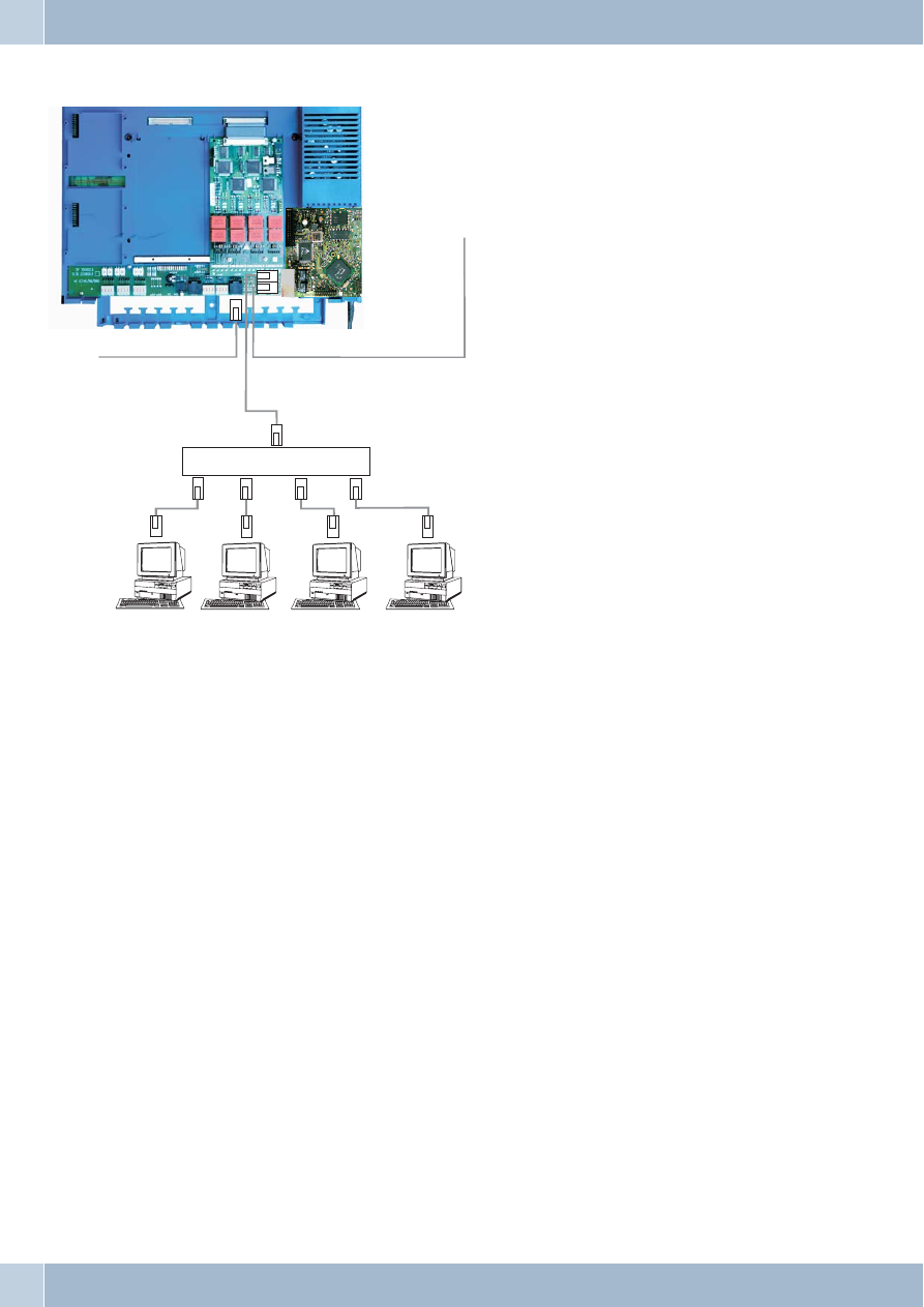
Configuration example for a network with DHCP address allocation
Configuration of the PABX system in its initial settings
Configuration examples
Router
21
IP-address of the
PABX:
192.168.1.250
Subnet mask:
255.255.255.0
Start address DHCP:
192.168.1.50
Number of DHCP addresses:
20
PC1.
IP via DHCP:
192.168.1.50 transmitted automatically via DHCP.
Gateway:
transmitted automatically via DHCP.
DNS server:
transmitted automatically via DHCP.
Subnet mask:
transmitted automatically via DHCP.
PC2.
IP via DHCP:
192. 168. 1. 51 transmitted automatically via DHCP.
Gateway:
transmitted automatically via DHCP.
DNS server:
transmitted automatically via DHCP.
Subnet mask:
transmitted automatically via DHCP.
PC3.
IP over DHCP:
192. 168. 1. 52 transmitted automatically via DHCP.
Gateway:
transmitted automatically via DHCP.
DNS server:
transmitted automatically via DHCP.
Router
Configuration examples
22
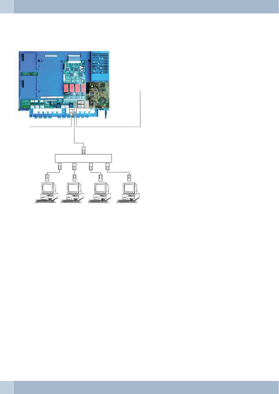
HUB / Switch
ISDN
WAN/xDS
PC1
PC2
PC3
PC4
Modul Router

Subnet mask:
transmitted automatically via DHCP.
PC4.
IP via DHCP:
192.168.1.53 transmitted automatically via DHCP.
Gateway:
transmitted automatically via DHCP.
DNS server:
transmitted automatically via DHCP.
Subnet mask:
transmitted automatically via DHCP.
In the example given here, the IP addresses for the clients (PCs) can lie within a range from IP 192. 168. 1. 50 to 192.
168. 1. 69. The IP addresses are assigned in the order that the clients (PCs) request them (for example by switching on
the PCs). If an IP address is released (for example by switching off a PC) that IP address is then available to be re-as-
signed again.
Configuration examples
Router
23
Address assignment without DHCP (set / mixed IP addresses)
You can dispense with a DHCP server in a network or also configure LAN clients (PCs) with set IP addresses as an ad-
dition to the DHCP clients.
Hinweis:
Much more time and effort is involved for configuring the network if a configuration is chosen without DHCP. If
you are relatively new to Windows network configuration, we recommend a configuration using DHCP.
Things to note for this configuration.
PABX:
You can de-activate the DHCP server for the PABX system using the »Professional Configurator« programme.
Hinweis:
You may have to adapt the IP addresses and subnetworks of the PABX system to the settings present on the LAN
clients (PCs). For information about this use the online Help function of the Configurator.
LAN-Client (PC) Configuration:
You must make the following minimum settings
manually:
IP address for the LAN client (PC)
Netmask / Subnet mask (which is also entered in
the PABX router)
IP address of the PABX system as the gateway
(interface to other networks, for example
Internet)
IP address of the PABX system as the DNS server
(server that converts the Internet addresses into
IP addresses)
Observe the instructions for address assignment
given on the previous pages.
PC settings in Windows operating system
The procedures described below deal only with
examples which may differ somewhat depending
on the operating system used and the configura-
tion of the PC.
Hinweis:
Please keep in mind that any changes made to the Windows network settings may have serious effects on the LAN
clients (PCs). Other methods of connection or applications may also be affected by these changes. In the event that
your network settings have already been changed contact your system administrator. You may have to backup all of
your data. The configuration presented in the following represents only one of many possibilities. These settings
are recommended. However, depending on the infrastructure of your environment, it may be meaningful to choose
a different configuration.
Router
Address assignment without DHCP (set / mixed IP addresses)
24
HUB / Switch
ISDN
WAN/xDS
PC1
PC2
PC3
PC4
Modul Router

Example Windows 98SE and Windows ME:
·
Open the Control Panel from the Windows Start Menu.
·
Open the »Network« folder
·
Select »TCP/IP« and click »Properties«.
·
Now select whether the PC is to receive its address automatically from a DHCP server, or if it is to
be assigned as permanent IP address. Edit or supplement the settings for network mask, gateway
and DNS server as appropriate. Refer to the parameters that are to be set in the sample configura-
tion with mixed address assignment, or in the sample configuration with set address assignment
on the following pages.
·
Confirm your settings by clicking OK.
Example Windows 2000 and Windows XP:
·
Open the Control Panel from the Windows Start Menu.
·
Under Windows 2000 open the folder »Network and Dial-up Connections«.
·
Under Windows XP open the folder »Network connections«.
·
Right-click on »LAN connection« and then click on »Properties«.
·
Select »TCP/IP« and click »Properties«.
·
Now select whether the PC is to receive its address automatically (from a DHCP server), or if it is
to be assigned as set (permanent) IP address. Edit or supplement the settings for network mask,
gateway and DNS server as appropriate. Refer to the parameters that are to be set in the sample
configuration with mixed address assignment, or in the sample configuration with set address as-
signment on the following pages.
·
Confirm your settings by clicking OK.
Also follow the instructions given in the documentation and the Help function of your operating system.
Hinweis:
A further option available is assigning a portion of the IP addresses manually and having the remaining addresses
allocated by DHCP. Ensure that the IP address for the router and any manually assigned IP addresses are not located
in the range for available DHCP addresses.
Address assignment without DHCP (set / mixed IP addresses)
Router
25
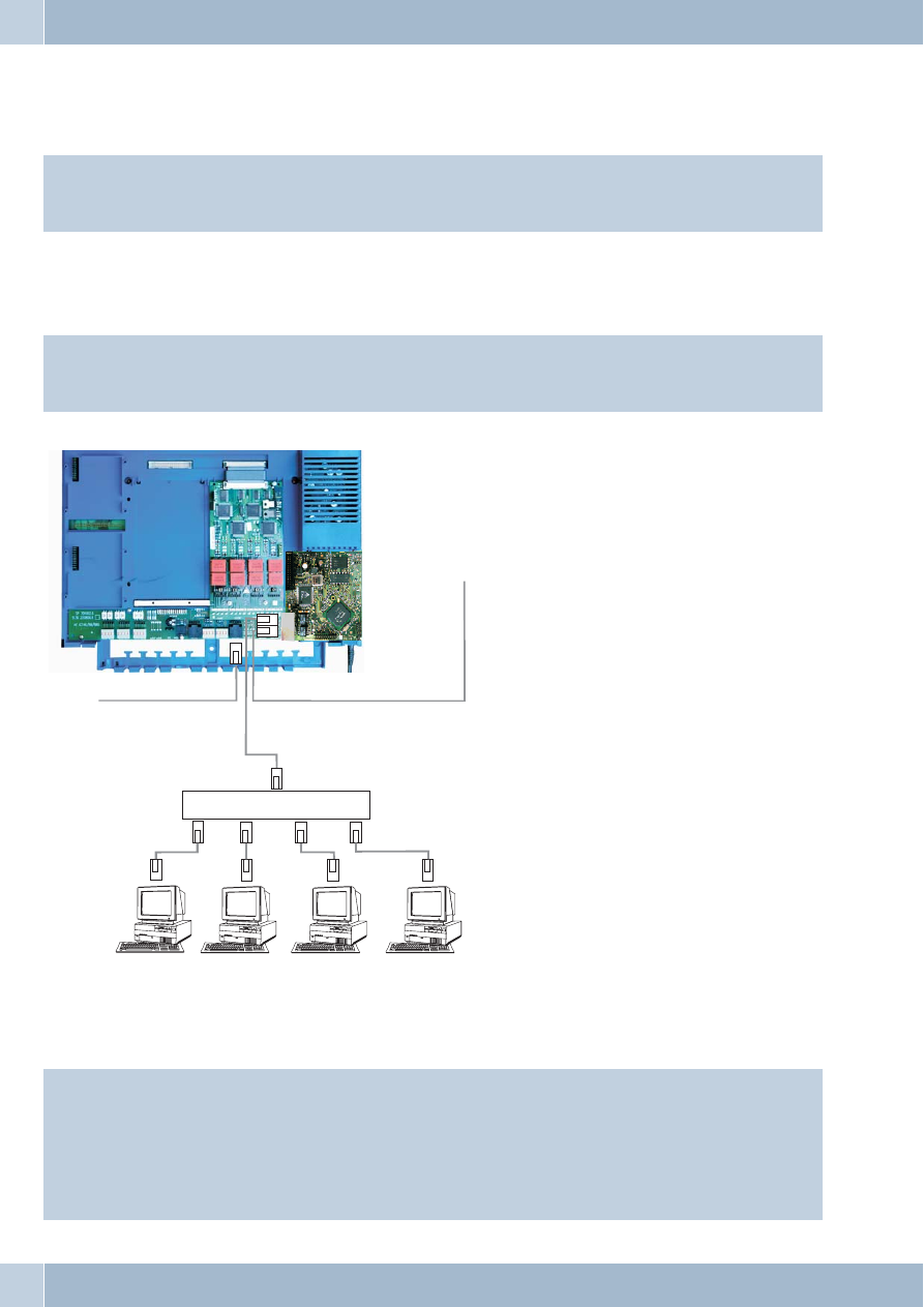
Sample configuration of a network with mixed address assignment
Set IP addresses and IP addresses allocated by DHCP
IP address of the
PABX:
192.168.1.250
Subnet mask:
255.255.255.0
Start address DHCP:
192.168.1.50
Number of DHCP addresses:
20
PC1.
Permanent IP:
192.168.1.92
Gateway:
192.168.1.250
DNS server:
192.168.1.250
Subnet mask:
255.255.255.0
PC2.
Permanent IP:
192.168.1.93
Gateway:
192.168.1.250
DNS server:
192.168.1.250
Subnet mask:
255.255.255.0
Router
Sample configuration of a network with mixed address assignment
26
HUB / Switch
ISDN
WAN/xDS
PC1
PC2
PC3
PC4
Modul Router

PC3.
IP over DHCP:
192.168.1.50 transmitted automatically via DHCP.
Gateway:
transmitted automatically via DHCP.
DNS server:
transmitted automatically via DHCP.
Subnet mask:
transmitted automatically via DHCP.
PC4.
IP via DHCP:
192. 168. 1. 51 transmitted automatically via DHCP.
Gateway:
transmitted automatically via DHCP.
DNS server:
transmitted automatically via DHCP.
Subnet mask:
transmitted automatically via DHCP.
Sample configuration of a network with set address assignment
IP address of the
PABX:
192.168.1.250
Subnet mask:
255.255.255.0
Start address DHCP:
DHCP server is off.
Number of DHCP addresses:
DHCP server is off.
PC1.
Permanent IP:
192.168.1.81
Gateway:
192.168.1.250
DNS server:
192.168.1.250
Subnet mask:
255.255.255.0
PC2.
Permanent IP:
192.168.1.82
Gateway:
192.168.1.250
DNS server:
192.168.1.250
Subnet mask:
255.255.255.0
PC3.
Permanent IP:
192.168.1.83
Gateway:
192.168.1.250
DNS server:
192.168.1.250
Subnet mask:
255.255.255.0
PC4.
Permanent IP:
192.168.1.84
Gateway:
192.168.1.250
DNS server:
192.168.1.250
Subnet mask:
255.255.255.0
Sample configuration of a network with set address assignment
Router
27

Checking the LAN clients (PCs)
Configuration for Windows 98SE/ME/2000/XP
If a connection to the PABX system, or to the Internet can not be set up you can check the configuration of the LAN
clients (PCs) based on the following information.
Hinweis:
The procedure described here assumes that you are using the recommended configuration with address as-
signment by DHCP.
The PC is linked to the PABX system via Ethernet (LAN1 or LAN2 jack).
·
Check to ensure that the network adapter installed in the LAN client (PC) is connected properly
to the PABX system. The connection status is displayed by the LEDs of the router module. A de-
scription of the LEDs is given in the operator’s manual for the PABX system.
·
Check to ensure that the PABX system has assigned an IP address to the LAN-Client (PC) (see
page in section »Checking the TCP/IP Configuration».
·
Check to ensure that an Internet service provider (ISP) has been configured in your PABX (see
operator’s manual for the PABX, leaflet »On the fast track to the Internet« or the online Help
function of your PABX system).
·
Check to ensure that the Internet browser(s) has(have) been configured correctly in your PC (see
Page in section »Internet Explorer settings / Windows Internet options«).
·
If you have made the settings as described above, the telephone system will establish a connection
to the Internet automatically (e. g. by opening the Internet Explorer, inputting an Internet URL
and confirming with “Enter”) when requested to do so by an application (default setting).
·
Check to ensure that automatic connection to the Internet has been de-activated (see
Configurator Network«, »Internet«); the connection must then be established manually via the
elmeg ControlCenter.
Router
Checking the LAN clients (PCs)
28
Checking the TCP/IP Configuration
The examples described below are base on the recommended network configuration with automatic address alloca-
tion. What this means is that the LAN clients get their IP address via DHCP (»IP address fetched automatically«) and
that the DHCP server in the PABX system is switched on (initial setting).
Windows 2000
·
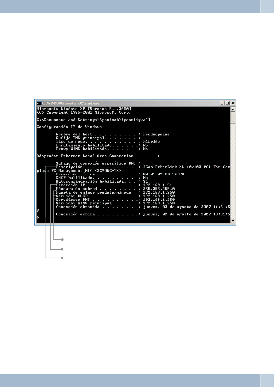
Start the program ipconfig.
Select »Run. . . « in the Windows start menu. Enter »cmd« and then click OK to confirm. Enter the
command »ipconfig/all« and then press Enter to confirm.
·
Current IP address of the pabx as gateway, DHCP server and DNS server.
·
Current IP address of the network adapter (client).
·
Select the network adapter connected to the pabx.
·
The values shown in the screen shot are set as defaults for the initial settings of the PABX system.
Depending on how many clients (PCs) are connected, the IP address lies within a range from 192.
168. 1. 50 to 192. 168. 1. 69. When these values are displayed, the network adapter and the Win-
dows network settings have been configured correctly.
·
The value for the physical address is different for each network adapter. The values for the lease
depend on when the PC is switched on.
·
If other data are shown, this may be due to the following reasons:
·
Changes have already been made to the initial setting for the PABX system in the Professional
Configurator.
Checking the TCP/IP Configuration
Router
29
·
The Windows network configuration for the client (PCs) does not correspond to the factory set-
tings Default setting.
·
Current IP address of the pabx as gateway, DHCP server and DNS server. Check your installation
as described in the operator’s manual for the PABX system (Installation and Commissioning sec-
tion).
·
The TCP/IP protocol is not installed on the PC, or it has no link to the network adapter connected
to the PABX system.
Windows XP
·
Open the Windows XP network connections.
Select the network adapter connected to the pabx by pressing the right mouse button. Then click
»Status«.
·
The values shown in the screen shot are set as defaults for the initial settings of the PABX system.
Depending on how many clients (PCs) are connected, the IP address lies within a range from 192.
168. 1. 50 to 192. 168. 1. 69. When these values are displayed, the network adapter and the Win-
dows network settings have been configured correctly. If other values are shown click the button
»Repair«.
·
The value for the physical address is different for each network adapter. The values for the lease
depend on when the PC is switched on.
Router
Checking the TCP/IP Configuration
30

If other data continues to be shown this may be due to the following reasons:
·
Changes have already been made to the initial setting for the PABX system in the Professional
Configurator.
·
The Windows network configuration for the client (PCs) does not correspond to the factory set-
tings Default setting.
·
Faulty installation of the network adapter in the client (PC), or the network adapter is not con-
nected properly with the PABX system. Check your installation as described in the operator’s
manual for the PABX system (Installation and Commissioning section).
·
The TCP/IP protocol is not installed on the PC, or it has no link to the network adapter connected
to the PABX system.
Configuring Internet Access on a PC
If you have used the Windows dial-up network for Internet access up to now, this connection was always established
as a »Dial-up connection« (analog or ISDN). Set-up and termination of an Internet connection was initiated auto-
matically by the programmes.
If you set up an Internet connection via the PABX system router, this represents a normal network connection for
each PC. If a PC wants to use an Internet connection the network router, which acts as a gateway and establishes con-
nections to other networks, is informed of this. The router, in our example here the PABX system, then sets up a con-
nection to one of the Internet service providers that has been configured. As defined in the configuration for the
PABX system, this connection is established/terminated automatically. The Internet service provider is configured
using the PABX system’s Configurator.
Internet Explorer settings / Windows Internet options
The following description illustrates the settings for Internet connections for the various operating systems. Proceed
as described below for your operating system and activate the corresponding option.
Windows 98SE:
Start Menu - Settings - Control Panel - Internet Options - Connections
Windows ME:
Start Menu - Settings - Control Panel - Internet Options - Connections
Windows 2000:
Start Menu - Settings - Control Panel - Internet Options - Connections
Windows XP:
Start Menu—-> Settings —-> Control Panel —-> Network and Internet Connections —-
Internet Options —- Connections
Configuring Internet Access on a PC
Router
31
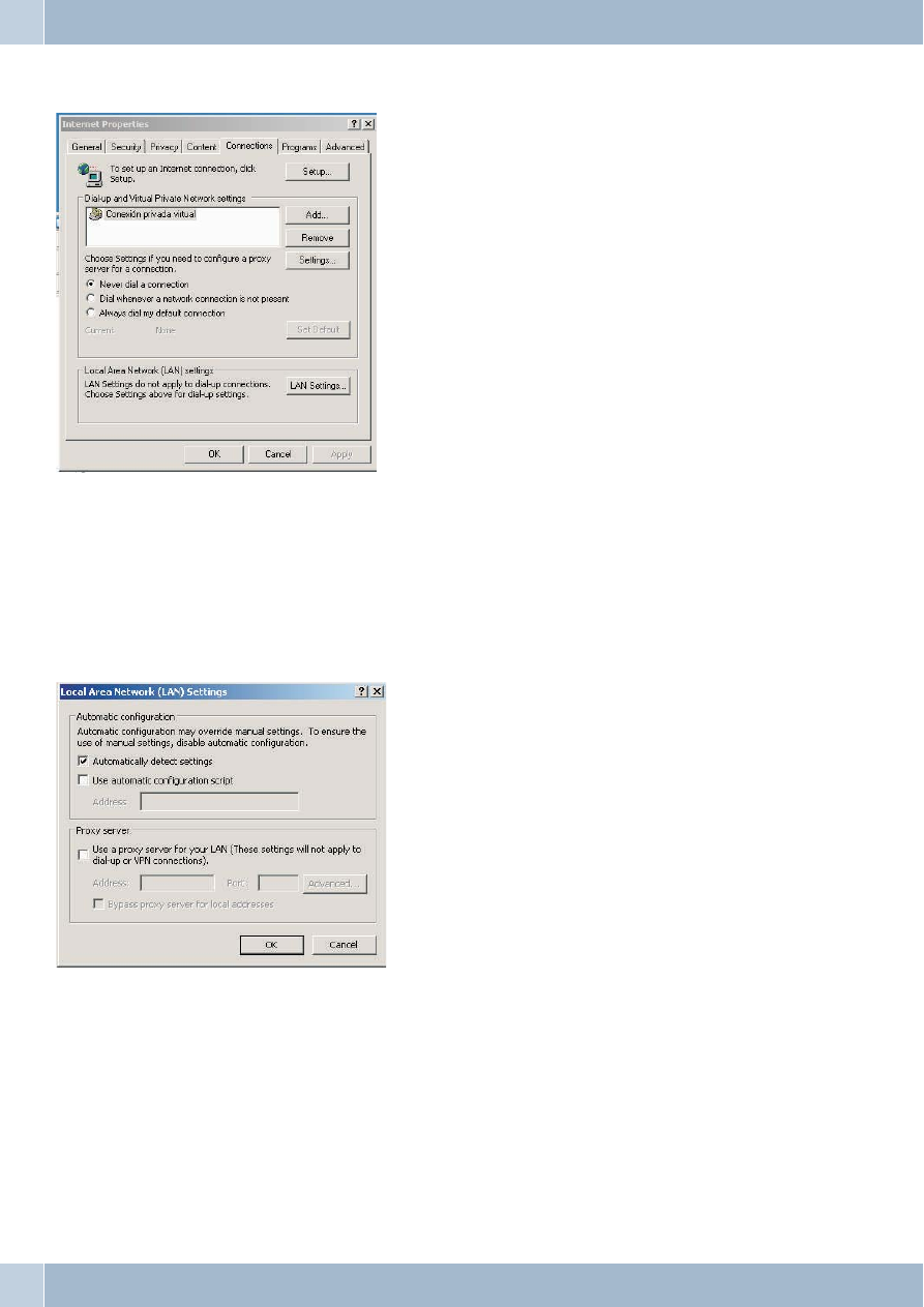
Dial-up connections configured at the client are displayed here. These connections are not required for accessing the
Internet with the pabx.
Check »Never«. You can use other devices besides your PABX system to hook up to the Internet. You may have to se-
lect the option »Dial whenever a network connection is not present«.
There are no settings required under »LAN Settings«.
Costs for Internet connections
The PABX saves several call data records. This data is not lost in the event of a loss of power.
Router
Costs for Internet connections
32

The PABX system also generates a call date record for connections made by the router. These data records contain
detailed information on a call. For ex.: Date and time, duration, number of caller and of party being called, type of
connection and data volume transferred (data sent / received).
Hinweis:
Please note that only the network service provider is authorized for binding connection/call cost logging.
Information about Data Security when Surfing the Internet
You should use a virus scanner on all LAN clients to protect your personal data. Use of this type of software is indis-
pensable for safeguarding personal data.
Information about Data Security when Surfing the Internet
Router
33

Funkwerk Enterprise Communications GmbH
Südwestpark 94
D-90449 Nürnberg
For information on support and service offerings please visit our Website at
www.Funkwerk-ec.com where, you will find a Service / Support area
Subject to modifications
Ausgabe 4 / 010109
Document Outline
- Table of contents
- Router 1
- Router of the ICT PABX system 1
- Default settings of the router 3
- Router functions 5
- Configuration of the Internet Service Provider (ISP) 8
- Configuring DHCP server and IP address allocation 10
- Configurating the Packet Filter Firewall 12
- Filter Wizard 15
- Configuring the PCs 20
- Configuration examples 20
- Address assignment without DHCP (set / mixed IP addresses) 24
- Sample configuration of a network with mixed address assignment 26
- Sample configuration of a network with set address assignment 27
- Checking the LAN clients (PCs) 28
- Checking the TCP/IP Configuration 29
- Configuring Internet Access on a PC 31
- Costs for Internet connections 32
- Information about Data Security when Surfing the Internet 33
- Router 1
Wyszukiwarka
Podobne podstrony:
Manual ICT 090101 Uk
ford km tool can bus user manual carsets co uk
Manuale configurazione router ( Sitecom PPPoE ) (1)
Short manual MI 3100 MI 3002 UK
BIOS Manual D27xx UK
uk ad pokarmowy
MonikiKamica uk éadu moczowego
Wybrane choroby nerek i uk adu oddechowego
PANsound manual
als manual RZ5IUSXZX237ENPGWFIN Nieznany
hplj 5p 6p service manual vhnlwmi5rxab6ao6bivsrdhllvztpnnomgxi2ma vhnlwmi5rxab6ao6bivsrdhllvztpnnomg
BSAVA Manual of Rabbit Surgery Dentistry and Imaging
Okidata Okipage 14e Parts Manual
Bmw 01 94 Business Mid Radio Owners Manual
Manual Acer TravelMate 2430 US EN
manual mechanika 2 2 id 279133 Nieznany
4 Steyr Operation and Maintenance Manual 8th edition Feb 08
więcej podobnych podstron