
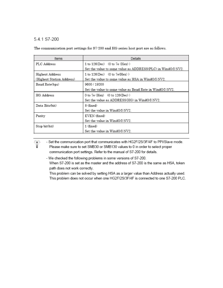
Communication Settings for
Siemens S7-200 (CPU 212)
and
IDEC Touchscreens
(5.7”HG2F, 10.4” HG3F, 12.1” HG4F)
Introduction
The information here will help you configure IDEC touchscreens (5.7” HG2F, 10.4”
HG3F, or 12.1” HG4F) and the Siemens S7-200 PLC using S7-200(PPI) protocol. For
other supported Siemens PLCs and communication settings/range of addresses, please
refer to the WindO/I-NV2 manual (click the link below). Select “Host Interface,” then
Connection to a PLC.
http://www.idec.com/Products/ENG/PDF/manuals/WindOI/V282/English/mainmenue.pd
f
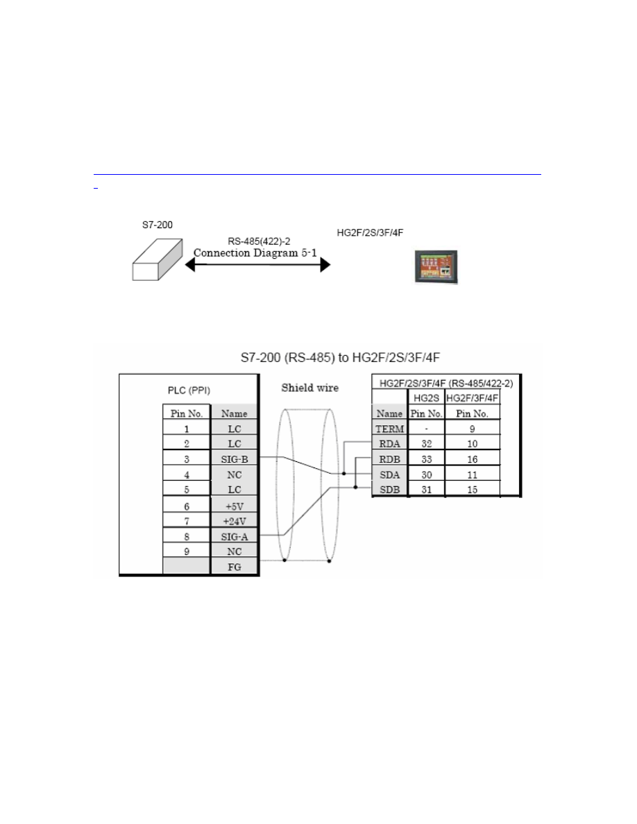
Cable information between S7-200 (CPU 212) to HG2F/3F/4F
Part number: HG9Z-2C155A
Wiring Diagram:
9 Pin Male Connector
25 Pin Male Connector
2
Communication Settings
3
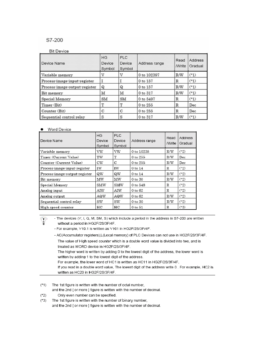
Available Addressing
4
Requirements for testing
1. Cable part no. HG9Z-XCM1A (programming cable between PC and HG2F/3F/4F)
2. Cable part no. HG9Z-2C155A (cable between Siemens S7-200 and HG2F/3F/4F)
3. Cable part no. PC/PP1 ( programming cable between PC and Siemens S7-200 )
4. HG9Y-ZSS2W (WindO/I-NV2 programming software for HG2F/3F/4F)
5. Siemens programming software called Step 7 Micro/WIN 32 (Windows-based )
Step 1: Software for Siemens S7-200 (Step 7 Micro/Win 32)
1. Siemens PLC used in this program: S7-200 CPU212
a) Connect part number PC/PPI cable from PC to Siemens S7-200.
The cable dip switches are set to 1=off, 2=on, 3=off, 4=off, 5=off.
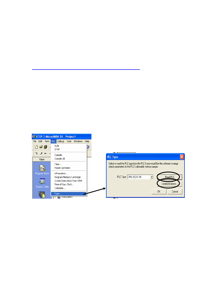
2. Launch Siemens programming software.
3. Select PLC – Type.
4. Next, click on the Read PLC button to read your PLC type.
5. Click on the Communications button and the settings should appear.
5
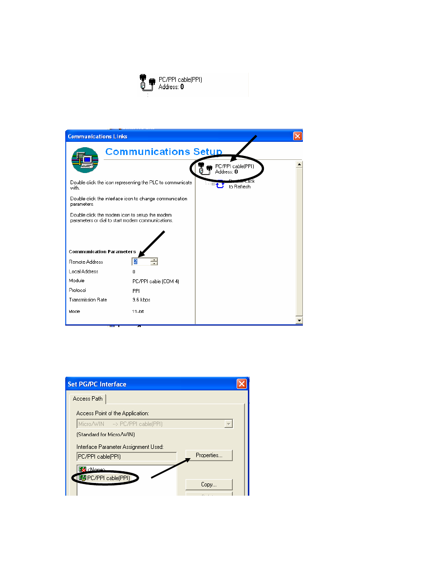
6. Assign the Remote Address ( in this testing, #2 is assigned).
7. Double click
8. In the Access Path, select PC/PPI cable (PPI).
a) Click the Properties button.
6
9. Local Connection:
a) Assign the COM Port. Check your COM port before assigning the
number.
10. PPI :
a) Assign the station address (#0 is assigned for this test)
b) Set the transmission rate at 9.6kbps
c) Highest node address is 31
d) Click the OK button to exit from the Properties dialogue box
11. Now, create a simple logic by clicking on the normally open contact / output coil
7
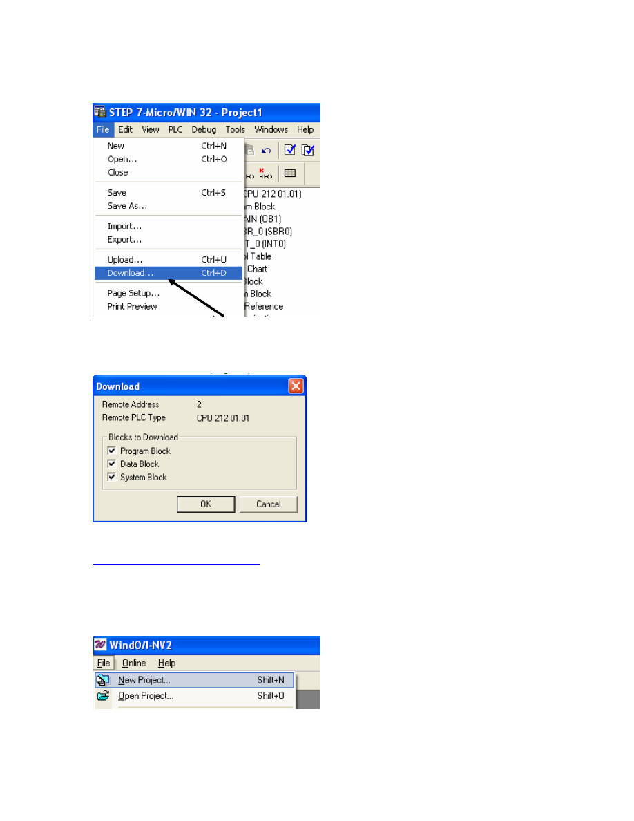
12. Download the project by selecting File-Download.
13. In the Download dialog box, follow all settings as shown in the image below and
then click the OK button to download.
Step 2: WindO/I-NV2 Software
1. Connect programming cable to PC and HG2F/3F/4F
2. Launch WindO/I-NV2
3. Select File/New Project
8
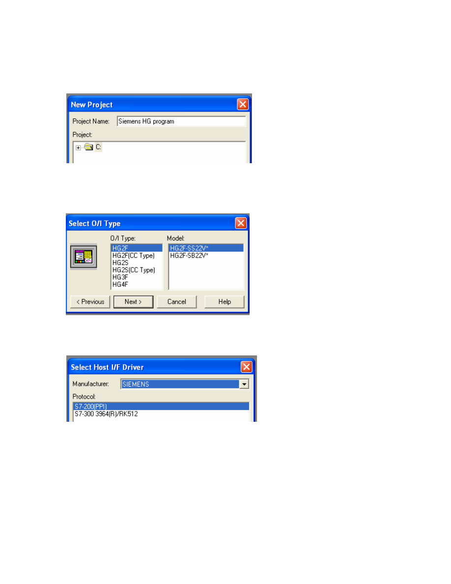
4. Create a project name. In this example, the project name is Siemens HG program.
Select the Next button to continue. It will tell you to “create project.” Select the
OK button.
5. Select the O/I and Model type. For testing purposes, HG2F is selected. Select the
Next button to continue.
6. In the Host I/F Driver, Siemens is selected for manufacturer and S7-200(PPI) for
protocol. Click the OK button.
7. In the Project Settings, select the Communication Interface tab.
- Under the Interface Configuration, select Serial 1 Host Communication.
- The Interface Settings are shown in the image below.
9
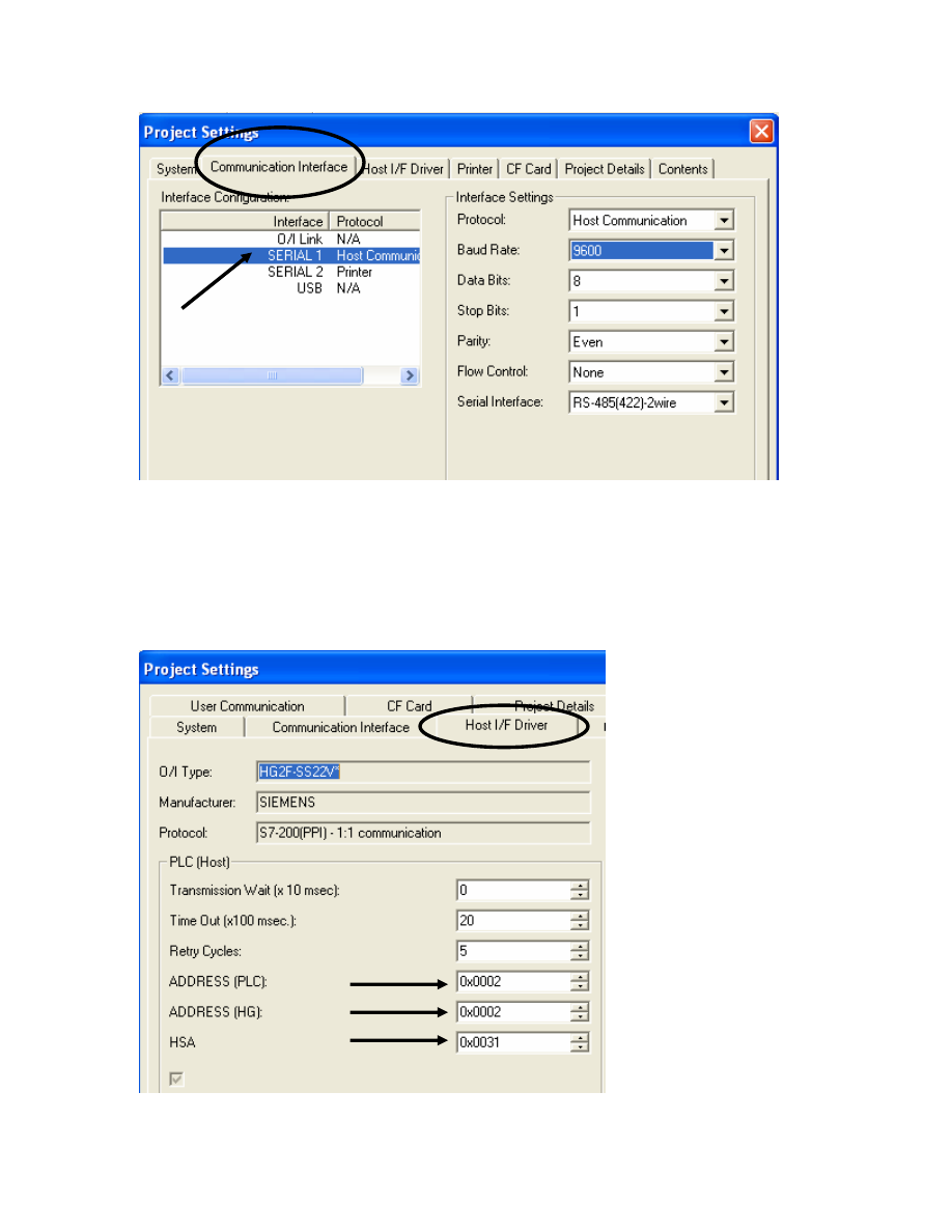
7. Next, select the Host/IF Driver tab.Make sure the settings in the Address [PLC],
Address [HG] and HSA match with the settings in the Siemens PLC. In this
example, the Address PLC and HG are assigned #2 and the HSA is # 31. These
are the settings from the PLC (see Step 7 & 10 above).
8. Select OK button to continue.
10
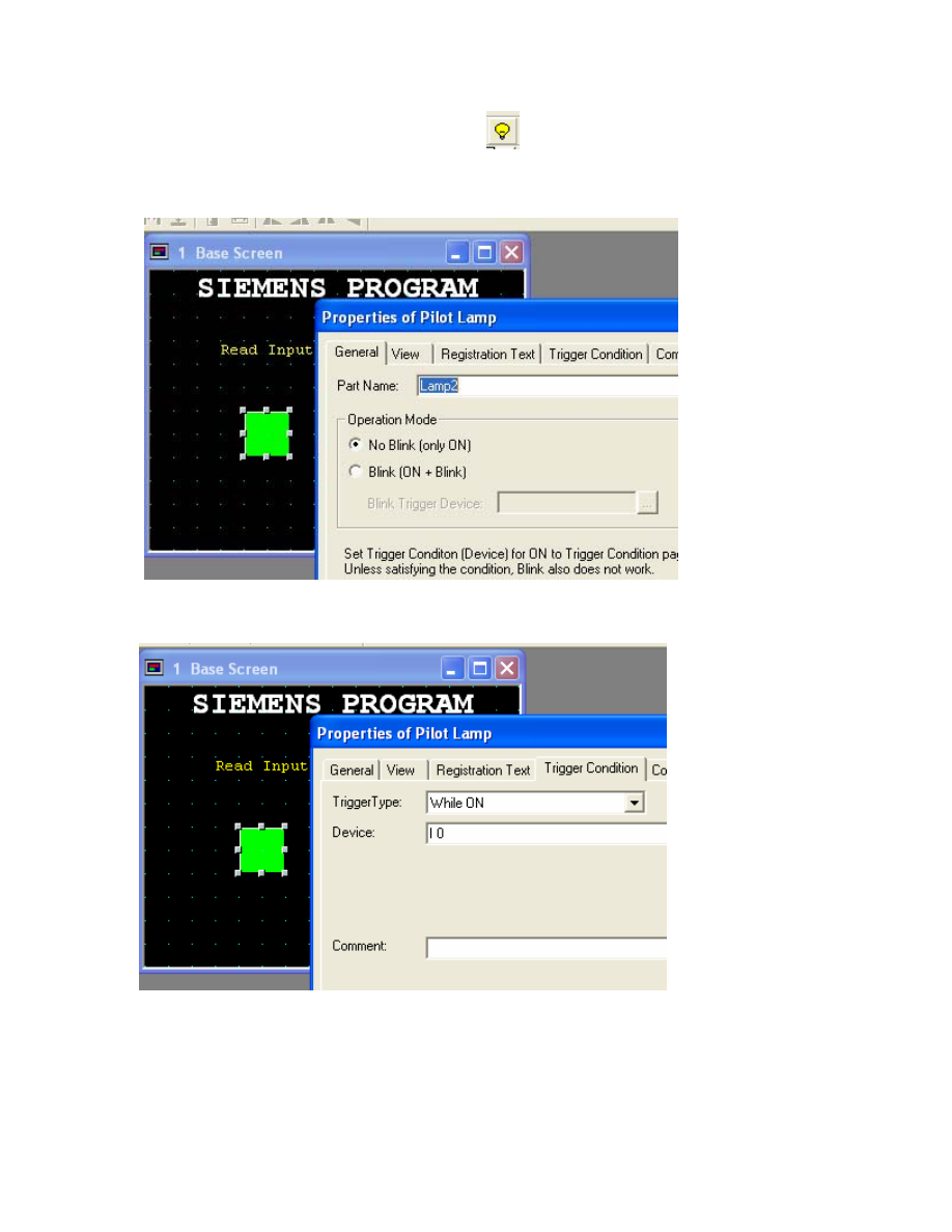
9. In Base Screen 1, select Pilot Lamp device
and drop it on the screen.
Double click on the device to set the properties. In the General tab under Operation
Mode, select No Blink.
10. In the Trigger Condition tab, select While ON and for Device select I0.
11

11. Once the settings are done, select the OK button to exit.
12. DOWNLOAD the project to the HG2F/3F/4F. Select Online-Download.
13. Now connect cable partnumber HG9Z-2C155A between the HG2F/3F/4F to
Siemens PLC.
If you are able to view the pilot lamp switching on/off based on the Input from the
PLC then the communication is successful. You may now continue with your project.
12
Wyszukiwarka
Podobne podstrony:
sterownik siemens s7 200
S7-200 - HSC, Automatyka, Siemens SIMATIC, S7-200, Programowanie
Basic setting for caustics effect in C4D
3 1 Pierwsze uruchomienie S7 200
general settings for user authentication and accounting
9 Sterowanie logiczne na bazie sterownika SIMATIC S7 200 oraz modelu przejścia dla pieszych
S7 200
MicroSystem S7 200
Nowości S7 200
Komunikacja PROFIBUS, S7 200, S7 300(1)
Programowanie sterownika PLC S7 200
kat skr S7 200 08 2008
Komunikacja MPI, S7 200, S7 300
Basic setting for caustics effect in C4D
3 1 Pierwsze uruchomienie S7 200
SIEMENS S7 300
więcej podobnych podstron