
Table of Contents
MS45 - E85 with M54 Engine
Subject
Page
Objectives of the Module . . . . . . . . . . . . . . . . . . . . . . . . . . . . . . . . . . . . . . .2
Purpose of the System . . . . . . . . . . . . . . . . . . . . . . . . . . . . . . . . . . . . . . . . .3
System Components . . . . . . . . . . . . . . . . . . . . . . . . . . . . . . . . . . . . . . . . . .4
Principle of Operation . . . . . . . . . . . . . . . . . . . . . . . . . . . . . . . . . . . . . . . . . .7
Workshop Hints . . . . . . . . . . . . . . . . . . . . . . . . . . . . . . . . . . . . . . . . . . . . . .8
Tools and Equipment . . . . . . . . . . . . . . . . . . . . . . . . . . . . . . . . . . . . . . . . . .9
Principle of Operation . . . . . . . . . . . . . . . . . . . . . . . . . . . . . . . . . . . . . . . . . .18
Workshop Hints . . . . . . . . . . . . . . . . . . . . . . . . . . . . . . . . . . . . . . . . . . . . . .22
Tools and Equipment . . . . . . . . . . . . . . . . . . . . . . . . . . . . . . . . . . . . . . . . . .25
Fuel Management . . . . . . . . . . . . . . . . . . . . . . . . . . . . . . . . . . . . . . . . . . . . .26
Principle of Operation . . . . . . . . . . . . . . . . . . . . . . . . . . . . . . . . . . . . . . . . . .32
Workshop Hints . . . . . . . . . . . . . . . . . . . . . . . . . . . . . . . . . . . . . . . . . . . . . .38
Tools and Equipment . . . . . . . . . . . . . . . . . . . . . . . . . . . . . . . . . . . . . . . . . .42
Ignition Management . . . . . . . . . . . . . . . . . . . . . . . . . . . . . . . . . . . . . . . . . .43
Principle of Operation . . . . . . . . . . . . . . . . . . . . . . . . . . . . . . . . . . . . . . . . . .48
Workshop Hints . . . . . . . . . . . . . . . . . . . . . . . . . . . . . . . . . . . . . . . . . . . . . .52
Tools and Equipment . . . . . . . . . . . . . . . . . . . . . . . . . . . . . . . . . . . . . . . . . .58
Emissions Management . . . . . . . . . . . . . . . . . . . . . . . . . . . . . . . . . . . . . . . .60
Evaporative Emissions . . . . . . . . . . . . . . . . . . . . . . . . . . . . . . . . . . . . . . . . .60
Exhaust Emissions . . . . . . . . . . . . . . . . . . . . . . . . . . . . . . . . . . . . . . . . . . . .64
Principle of Operation . . . . . . . . . . . . . . . . . . . . . . . . . . . . . . . . . . . . . . . . . .70
Workshop Hints. . . . . . . . . . . . . . . . . . . . . . . . . . . . . . . . . . . . . . . . . . . . 81
Tools and Equipment . . . . . . . . . . . . . . . . . . . . . . . . . . . . . . . . . . . . . . . . 83
Performance Controls . . . . . . . . . . . . . . . . . . . . . . . . . . . . . . . . . . . . . . . . . .84
Tools and Equipment . . . . . . . . . . . . . . . . . . . . . . . . . . . . . . . . . . . . . . . . 91
Review Questions . . . . . . . . . . . . . . . . . . . . . . . . . . . . . . . . . . . . . . . . . . . 92

2
MS45
Objectives of the Module
After completing this module, you will be able to:
• Describe the Power Supply for the Fuel Injectors and Ignition Coils.
• Understand the EDK and Idle Air Actuator Operation.
• Name the Differences of the MS45 Fuel Supply System.
• List the Inputs Required for Fuel Injector Operation.
• Describe Emission Optimized Function.
• Name the Two Types of Emissions the ECM Controls.
• Explain Why Two Sensors are Used to Monitor Accelerator Pedal Movement.
• Understand DM TL Evaporative Leak Testing.
• Describe How the Ignition System is Monitored.
MS45
Models: E85 Z4 - with M54 Engine
Production Date: Start of Production MY 2003
Manufacturer: Siemens
Pin Connector: 134 Pins - 5 Modular Connectors
3
MS45
MS45
Purpose of the System
The MS45 system is an evolution of the MS43 system and manages the following func-
tions:
DME
Air:
• Idle Speed Valve
• Electronic Throttle
• Hot Film Air Mass Meter
• Resonance-Turbulence
Intake Control
Fuel:
• Fuel Supply (Non-Return)
• Fuel Injection
Ignition:
• Direct Ignition/Optimized
• Knock Control
• Ignition Monitoring
Emissions:
• OBD Compliant
• Secondary Air Injection
• Pre and Post Oxygen Sensors
• Oxygen Sensor Heating
• MAP Thermostat
• Misfire Detection
• Evaporative Emission Control and Leak
Detection
• Ambient Pressure Sensing
• Malfunction Indicator Light
Performance Controls:
• Dynamic Driving Control “Sport” Mode
• Dual VANOS Control
• Electric Cooling Fan
• Ebox Fan Control
• PT CAN Bus Communication
• EWS III (3.3)
• Cruise Control
• Alternator Interfacing (BSD)
• ECM Programming
MS45
4
MS45
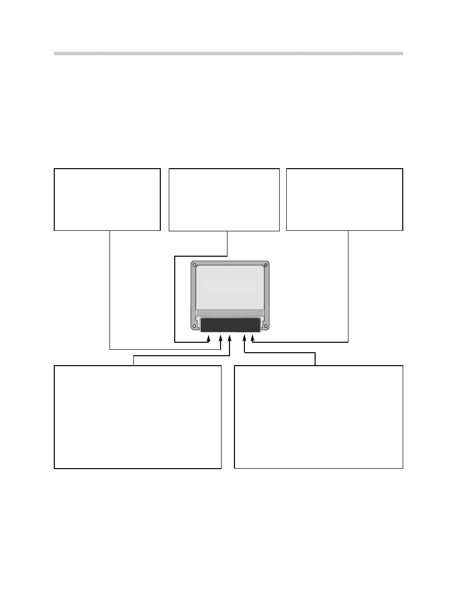
System Components
MS45 Engine Control Module: The Engine Control Module (ECM) features a single
printed circuit board with two 32-bit microprocessors.
The task of the first processor is to control:
• Engine Load
• Electronic Throttle
• Idle Actuator
• Ignition
• Knock Control
The task of the second processor is to control:
• Air / Fuel Mixture
• Emission Control
• Misfire Detection
• Evaporative Leak Detection
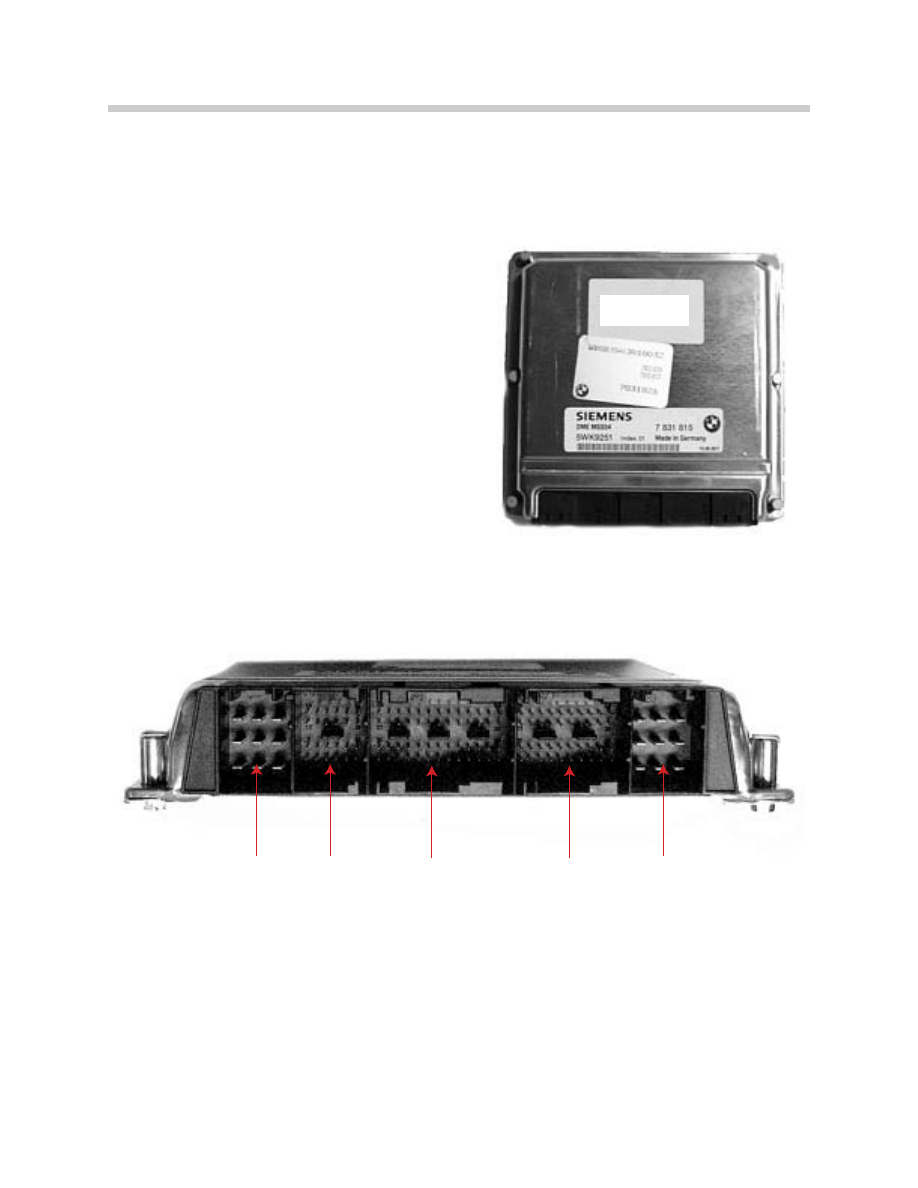
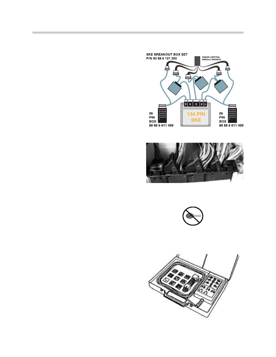
The 134 pin ECM is manufactured by Siemens to BMW specifications. The ECM is the SKE
(standard shell construction) housing and uses 5 modular connectors. For testing, use the
Universal Adapter Set (break-out box) Special Tool # 90 88 6 121 300.
X60001
9 - Pin
X60002
24-Pin
X60003
52 - Pin
X60004
40 - Pin
X60005
9 - Pin
12550000.tiff
MS45
5
MS45
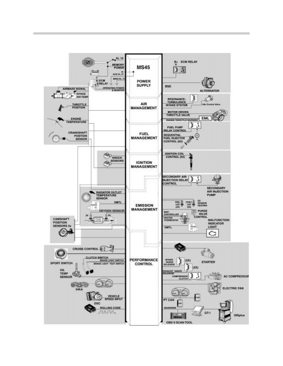
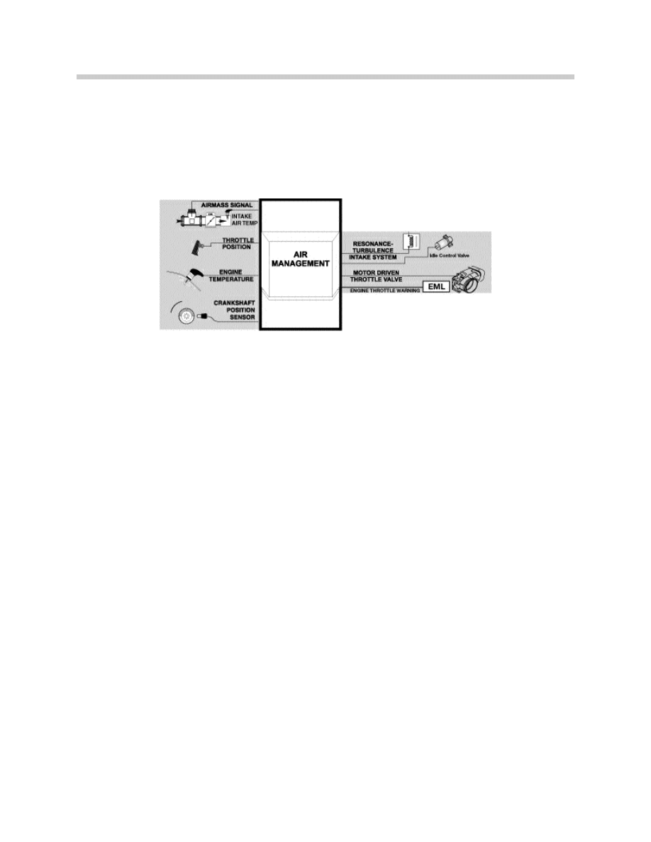
System Components: Inputs - Processing - Outputs
45-02-01
6
MS45 Power Supply
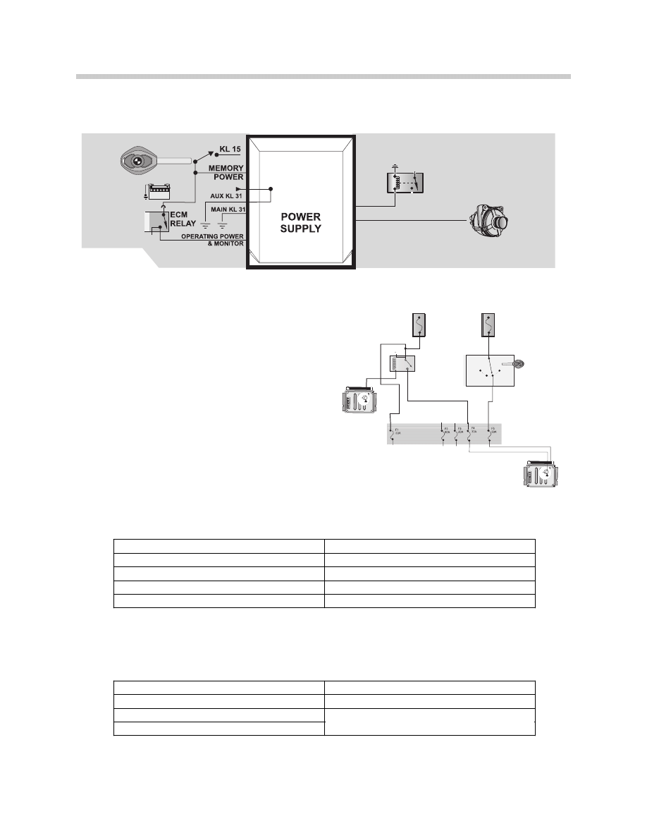
Power Supply
KL30 - Battery Voltage: B+ is the main supply of operating voltage to the ECM.
Power Supplies: The power supplies (KL15
and ECM Relay) are fused to the MS45 ECM.
The fuses are housed in the Engine Fuse Block
located in the Electronics Box.
KL15 - Ignition Switch: When the ignition is
switched “on” the ECM is informed that the en-
gine is about to be started. KL15 (fused) sup-
plies voltage to the Engine Control Module
Relay and the Fuel Injector Relay. Switching
KL15 “off” removes the ECM operating voltage.
Engine Control Module Relay: The ECM Relay provides the operating voltage for:
Ground: Multiple ground paths are necessary to complete current flow through the ECM.
ALTERNATOR
B+
BSD
ECM RELAY
MS45
ECM
ECM
ECM Fuses
ECM
Relay
Ignition Switch
F109
80 Amps
F114
50 Amps
0
R
15
50
55-01-01
1. ECM
6. Ignition Coil
2. Fuel Injection
7. Evaporative Leak Detection Pump
3. Idle Air Actuator
8. Camshaft Sensor
4. Evaporative Emission Valve
9. Hot Film Air Mass
5. Fuel Pump Relay
10. Oxygen Sensor Heaters
Connector X60001
Connector X60005
Pin 4 – Ground for ECM
Pin 5 – Ground for ECM
Pin 5 – Ground for ECM
Pin 6 – Ground for ECM (MS42)
Pin 6 – Ground for ECM
45-02-02
7
MS45 Power Supply
Principle of Operation
Battery Voltage is monitored by the ECM for fluctuations. It will adjust the output func-
tions to compensate for a lower (6v) and higher (14v) voltage value. For example, the ECM
will:
• Modify pulse width duration of fuel injection
• Modify dwell time of ignition
When KL15 is switched “on” the ECM is ready for engine management. The ECM will acti-
vate ground to energize the Engine Control Module Relay. The Engine Control Module
Relay supplies operating voltage to the ECM and the previously mentioned operating com-
ponents. Five seconds after the ignition is switched on and the voltage at the KL15 input
is >9 volts, the ECM compares the voltage to the ECM Relay supplied voltage. If the volt-
age difference between the two terminals is greater than 3 volts, a fault code will be set.
When KL15 is switched “off” the ECM operating voltage is removed. The ECM will main-
tain a ground to the Engine Control Module Relay for a few seconds to maintain ignition coil
activation (Emission Optimized) and as long as three minutes to complete the DM TL test.
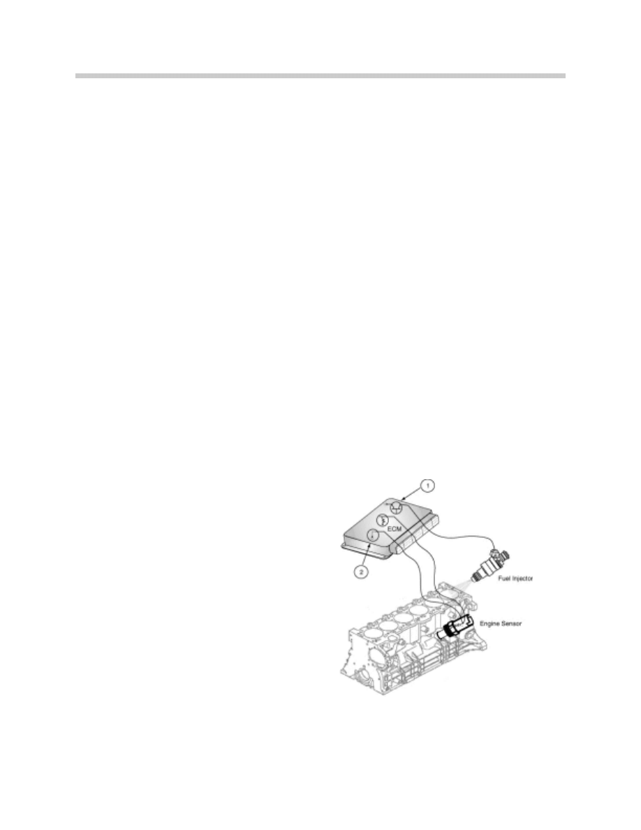
Ground is required to complete the cur-
rent path through the ECM. The ECM also:
• Internal links a constant ground (1) to activate
components
• Switches ground (2) to activate components
55-01-04
8
MS45 Power Supply
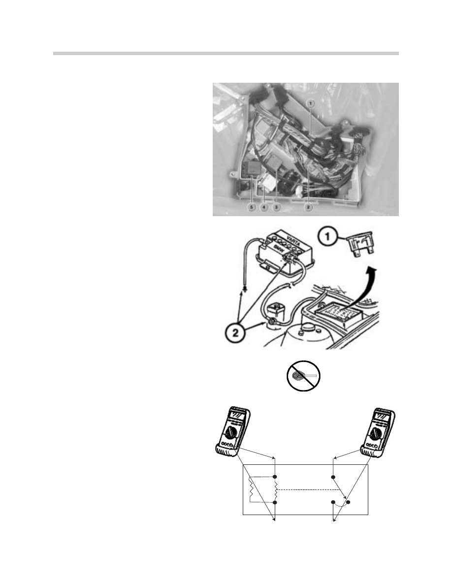
Workshop Hints
Power Supply - Testing
1. ECM (DME)
2. EGS or SMG (if equipped)
3. ECM main relay
4. Fuel injector relay
5. - SMG (if equipped) hydraulic pump relay
- EGS (if equipped) reverse light relay
Inadequate power and ground supply
can result in:
1. No Start
2. Hard Starting (Long Crank Times)
3. Inaccurate Diagnosis Status or ECM (not found)
4. Intermittent/Constant “Engine Emission/EML”
Light
5. Intermittent/Constant Driveability Problems
Power supply including fuses should be
tested.
The ignition (KL15) must be switched off
when removing or installing the ECM
connector to prevent voltage spikes (arc-
ing) that can damage the Control
Module!
The Engine Control Module Relay (locat-
ed in the Electronics Box) should be test-
ed for:
1. Battery Voltage and Switched Ground (1)
2. Resistance (1)
3. Battery Voltage and Voltage Drop (2)
E85 Electronics Box - ECM and Fuses
12550001
1
2
86
30
85
87
12410004
9
MS45 Power Supply
Tools and Equipment
Power Supply
When testing power supply to an ECM, the
DISplus/GT1 multimeter function as well as a
reputable hand held multimeter can be used.
It is best to make the checks at the ECM con-
nection, this method includes testing the wiring
harness.
The correct Universal Adapter for the MS45
application should be used (#90 88 6 121 300).
This will ensure the pin connectors and the har-
ness will not be damaged.
When installing the Universal Adapter to the
ECM (located in the Electronics Box in the
engine compartment), make sure the ignition is
switched off.
NOTE for MS45: Allow at least 3 minutes to
elapse after the key was set to the “OFF” posi-
tion before disconnecting the ECM/ TCM.
This will allow sufficient time to complete the
DM TL test. Voltage may be present (up to 3
minutes) causing damage to the ECM/TCM if
they are disconnected during this time period
(arcing).
The Engine Control Module Relay should be
tested using the relay test kit (P/N 88 88 6 613
010) shown on the right.
This kit allows testing of relays from a remote
position. Always consult the ETM for proper
relay connections.
12550001
16550020
12550003
10
MS45 Air Management
Air Management
Throttle Valve: The throttle valve plate is electronically operated to regulate intake air flow
by the ECM. The purpose is for precision throttle operation, OBD compliant for fault moni-
toring, DSC and Cruise Control. This integrated electronic throttle reduces extra control
modules, wiring, and sensors. Adjusting electronic throttles is not permitted, the throttle
assembly must be replaced as a unit. The adaptation values must be cleared and adapta-
tion procedure must be performed using the DISplus/GT1.
The throttle assembly for the MS45 system is
referred to as the EDK. The EDK is distin-
guished by:
• EDK does not contain a PWG, It is remotely mounted
(integrated in the accelerator pedal assembly).
• The accelerator pedal is not mechanically “linked” to the
EDK.
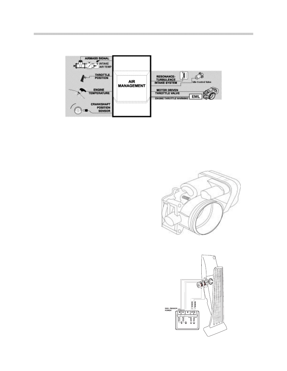
Throttle Position Sensor: The accelerator
pedal module provides two variable voltage sig-
nals to the ECM that represents accelerator
pedal position and rate of movement.
Dual Hall Sensors are integral in the accelerator
pedal module. The ECM compares the two val-
ues for plausibility. The module contains internal
springs to return the accelerator pedal to the
rest position.
16550007
MS S54
13550011.eps
45-02-03
11
MS45 Air Management
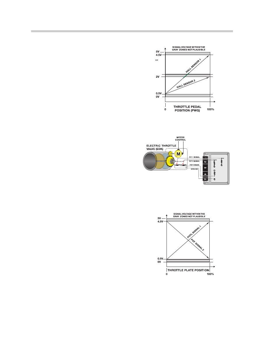
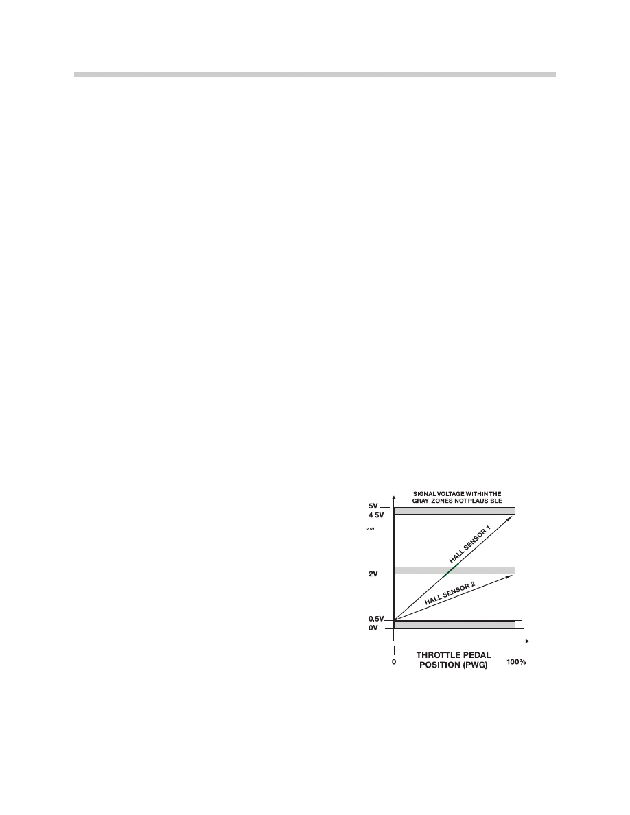
The ECM provides voltage (5v) and ground for
the Hall sensors. As the accelerator pedal is
moved from rest to full throttle, the sensors pro-
duce a variable voltage signal.
• Hall sensor 1(request) = 0.5 to 4.5 volts
• Hall sensor 2 (plausibility) = 0.5 to 2.0 volts
If the signals are not plausible, the ECM will use
the lower of the two signals as the requested
input. The throttle response will be slower and
the maximum throttle response will be reduced.
Throttle Motor and Feedback Position: The
MS45 ECM powers the EDK motor using pulse
width modulation for opening and closing the
throttle plate. The throttle plate is also closed by
an integrated return spring.
Two integrated potentiometers provide voltage
feedback signals to the ECM as the throttle plate
is opened and closed.
• Feedback signal 1 provides a signal from 0.5v (closed) to
4.5 V (Full Throttle)
• Feedback signal 2 provides a signal from 4.5v (closed) to
0.5V (Full Throttle)
Potentiometer 1 is the primary feedback signal
of throttle plate position and signal 2 is the plau-
sibility cross check through the complete throt-
tle plate movement.
13550012
13550002
13550005
12
MS45 Air Management
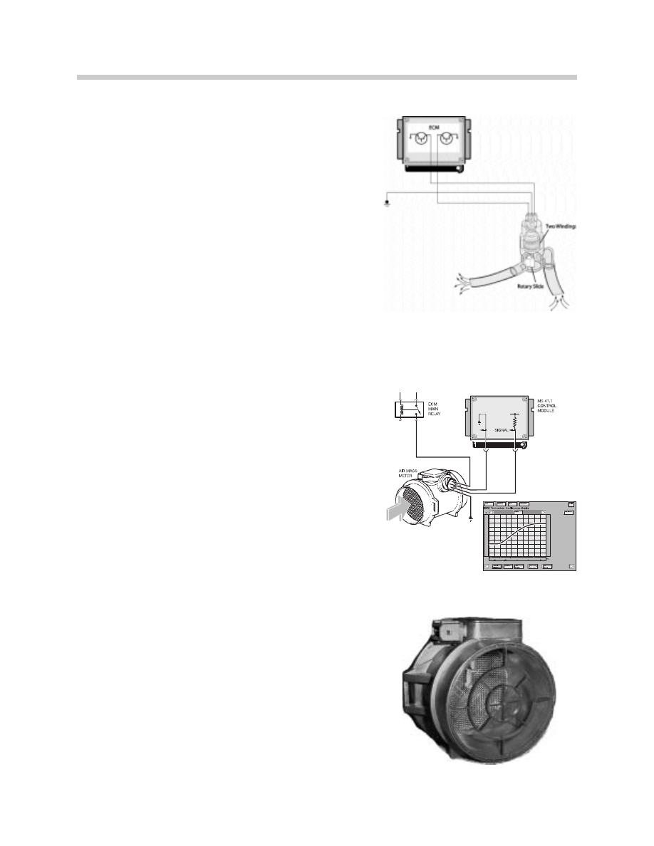
Idle Air Actuator: This valve regulates air by-passing
the throttle valve to control the engine idle/low speed.
The valve is supplied with battery voltage from the ECM
Relay. The Idle Air Actuator is a two-coil rotary actua-
tor. The ECM is equipped with two final stage transis-
tors which will alternate positioning of the actuator.
The final stages are "pulsed" simultaneously by the
ECM which provides ground paths for the actuator.
The duty cycle of each circuit is varied to achieve the
required idle RPM.
If this component/circuits are defective, a fault code will
be set and the “Malfunction Indicator Light” will be illu-
minated when the OBD II criteria is achieved.
Hot-Film Air Mass Meter (HFM): The air volume
input signal is produced electronically by the HFM
which uses a heated metal film (180º C above intake air
temperature) in the air flow stream.
The ECM Relay provides the operating voltage. As air
flows through the HFM, the film is cooled changing the
resistance which affects current flow through the cir-
cuit. The sensor produces a 1-5 volt varying signal.
Based on this change the ECM monitors and regulates
the amount of injected fuel.
If this input is defective, a fault code will be set and the
“Malfunction Indicator Light” will be illuminated when
the OBD II criteria is achieved. The ECM will operate
the engine using the Throttle Position and Engine RPM
inputs.
NOTE: The HFM is non-adjustable.
16550008
7
8
13550017
13550004

13
MS45 Air Management
Air Temperature Signal: The HFM contains an integral air temperature sensor. This is a
Negative Temperature Coefficient (NTC) type sensor. This signal is required by the ECM to
correct the air volume input for changes in the intake air temperature (air density) affecting
the amount of fuel injected, ignition timing and Secondary Air Injection activation.
The ECM provides the power supply to the sensor which decreases in resistance as the
temperature rises and vice versa. The ECM monitors an applied voltage to the sensor that
will vary as air temperature changes the resistance value.
If this input is defective, a fault code will be set and the
“Malfunction Indicator Light” will be illuminated when the OBD
II criteria is achieved. The ECM will operate the engine using
the Engine Coolant Sensor input as a back up.
Notes:
13550004
14
MS45 Air Management
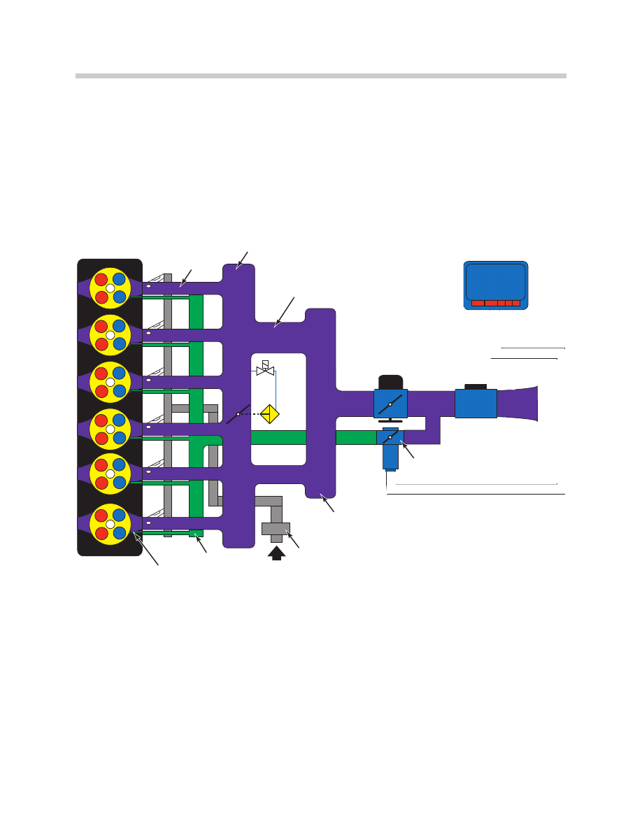
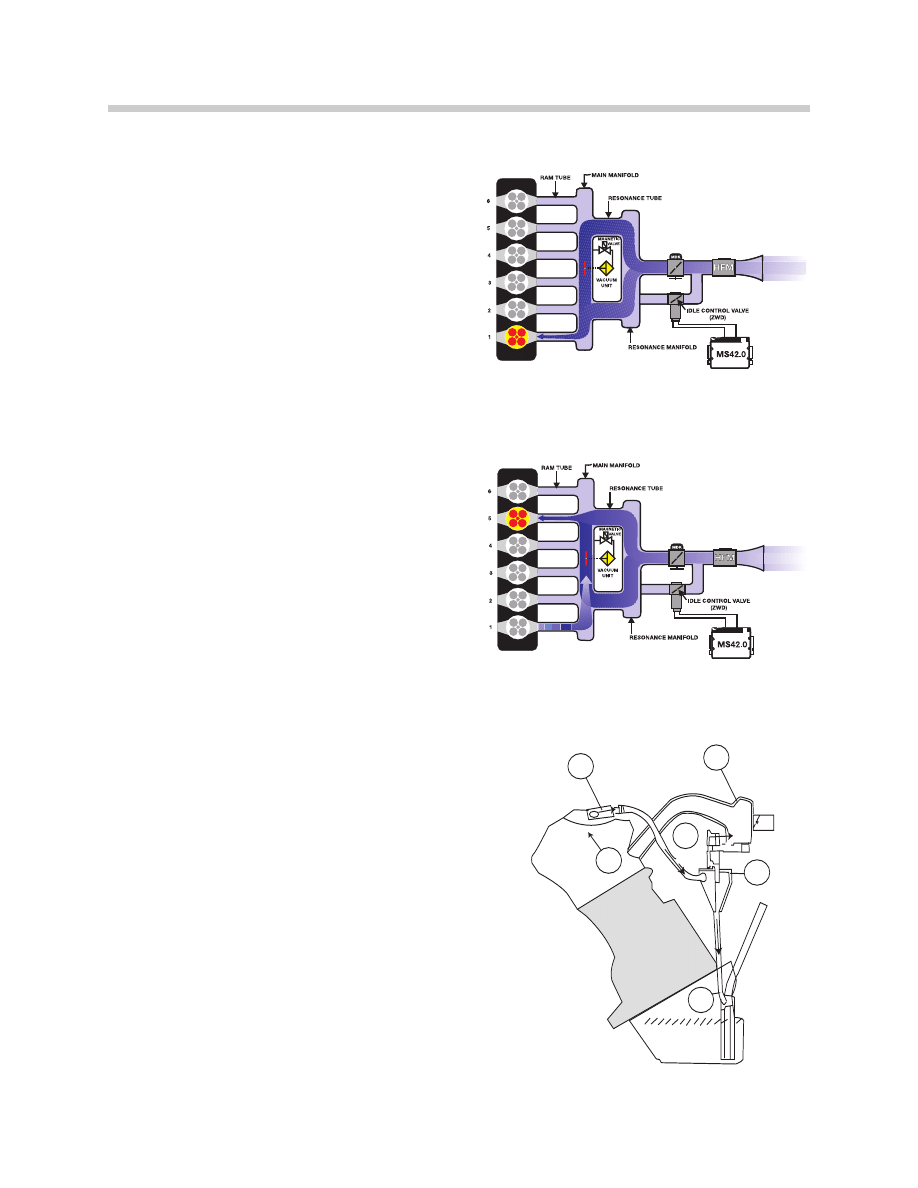
Resonance/Turbulence Intake System: On the M54, the intake manifold is split into two
groups of three (runners) which increases low end torque. The intake manifold also has
separate (internal) turbulence bores which channels air from the idle speed actuator direct-
ly to one intake valve of each cylinder (matching bore of 5.5mm in the cylinder head).
Routing the intake air to only one intake valve causes the intake to swirl in the cylinder.
Together with the high flow rate of the intake air due to the small intake cross sections, this
results in a reduction in fluctuations and more stable combustion.
Resonance System: The resonance system provides increased engine torque at low
RPM, as well as additional power at high RPM. Both of these features are obtained by
using an ECM controlled resonance flap (in the intake manifold).
During the low to mid range rpm, the resonance flap is closed. This produces a long/sin-
gle intake tube which increases engine torque.
During mid range to high rpm, the resonance flap is open. This allows the intake air to draw
through both resonance tubes, providing the air volume necessary for additional power at
the upper RPM range.
MDK
HFM
MAGNETIC
VALVE
VACUUM
UNIT
MS42.0
RAM TUBE
MAIN MAINIFOLD
RESONANCE TUBE
IDLE AIR CONTROL VALVE
(ZWD)
RESONANCE MANIFOLD
CRANKCASE VENTILATION
TURBULENCE MANIFOLD
TURBULENCE BORE 0:5.5mm
135500011
15
MS45 Air Management
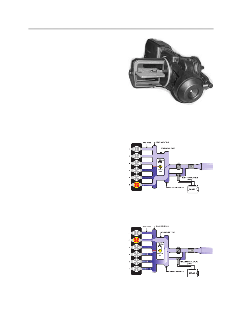
The Resonance Flap (shown on the right) is
closed when vacuum is applied and sprung
open. This is a unitized assembly that is bolted
into the intake manifold.
The ECM controls a solenoid valve for reso-
nance flap activation. At speeds below 3750
RPM, the solenoid valve is energized and vac-
uum supplied from an accumulator closes the
resonance flap. This channels the intake air
through one resonance tube, but increases the
intake velocity.
When the engine speed is greater than 3750
RPM (which varies slightly - temperature influ-
enced), the solenoid is de-energized. The reso-
nance flap is sprung open, allowing flow through
both resonance tubes, increasing volume.
When the flap is closed, this creates another
“dynamic” effect.
• #1 Cylinder Intake Valve open low to Mid Range RPM
(<3750 RPM).
• #1 Cylinder Intake Valve closes #5 Intake Valve Open =>
Intake Air Bounce Effect low to Mid Range RPM (<3750
RPM).
As the intake air is flowing into cylinder #1, the
intake valves will close.
This creates a “block” for the in rushing air. The
air flow will stop and expand back (resonance
wave back pulse) with the in rushing air to cylin-
der #5.
• #1 Cylinder Intake Valve closes #5 Intake Valve Open =>
Intake Air Bounce Effect Low to Mid Range RPM (<3750
RPM)).
The resonance “wave”, along with the intake
velocity, enhances cylinder filling.
135500012
13550010
13550009
16
MS45 Air Management
When the engine speed is greater than 3750
RPM the solenoid is de-energized. The reso-
nance flap is sprung open, allowing flow through
both resonance tubes, increasing volume.
• #1 Cylinder Intake Valve Open - Intake air drawn from both
resonance tubes. Mid to High Range (>3750 RPM)
• #5 Cylinder Intake Valve Open - Intake air drawn from both
resonance tubes. Mid to High Range RPM (>3750 RPM).
The resonance “wave”, along with the intake
volume, enhances cylinder filling.
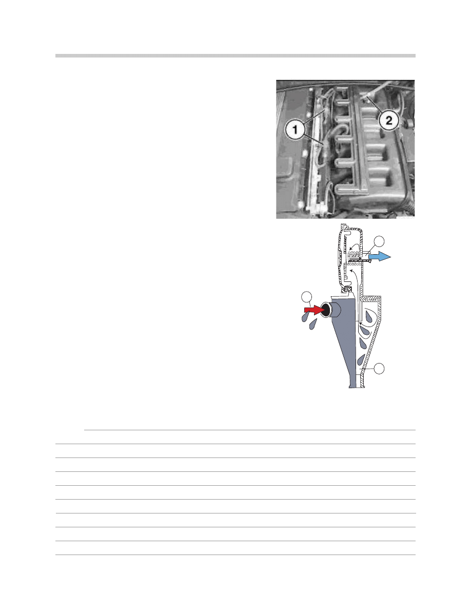
Pressure Control Valve: The pressure control
valve varies the vacuum applied to the
crankcase ventilation depending on engine
load. The valve is balanced between spring
pressure and the amount of manifold vacuum.
The oil vapors exit the separator labyrinth (2) in
the cylinder head cover (1). The oil vapors are
drawn into the cyclone type liquid/vapor sepa-
rator (3) regulated by the pressure control valve
(5).
The oil vapors exit the pressure control valve
into the intake manifold. The collected oil will
drain back into the oil pan (4).
13550008
13550000007
1
2
6
5
3
4
11550006
17
MS45 Air Management
The vapors exit the pressure control valve and are
drawn into the intake manifold through an external dis-
tribution tube (2). The tube has a splice at the front to
equally distribute vapors to the back.
As the vapors exit the pressure control valve, they are
drawn into the intake manifold through this external
tube for even distribution.
At idle when the intake manifold vacuum is high, the
vacuum reduces the valve opening allowing a small
amount of crankcase vapors to be drawn into the
intake manifold.
At part to full load conditions when intake manifold
vacuum is lower, the spring opens the valve and addi-
tional crankcase vapors are drawn into the intake man-
ifold.
1. Engine Oil Vapors
2. Collective Drain Back Oil
3. Oil Vapors to the Intake Manifold
Notes:
1
3
2
11550007
135500021
18
MS45 Air Management
Principle of Operation
Air flow into the engine is regulated by the Throttle Valve and/or the Idle Air Actuator. Both
of these air “passages” are necessary for smooth engine operation from idle to full load. On
the MS45 system, the Throttle Valve and the Idle Air Actuator are electrically controlled. All
of the ECM monitoring, processing and output functions are a result of regulated air flow.
The Accelerator Pedal Position (PWG) is monitored by the ECM for pedal angle posi-
tion and rate of movement. As the accelerator is moved, a rising voltage signal from the
potentiometers/Hall sensors requests acceleration and at what rate. The ECM will increase
the volume of fuel injected into the engine, advance the ignition timing and open the Throttle
Valve and/or Idle Air Actuator.
The “full throttle” position indicates maximum acceleration to the ECM, and in addition to
the functions just mentioned, this will have an effect on the air conditioning compressor
(covered in Performance Controls).
As the accelerator pedal is released (integral springs), a decrease in voltage signals the
ECM to activate fuel shut off if the RPM is above idle speed (coasting). The Throttle Valve
will be closed and Idle Air Actuator Valve will open to maintain idle speed.
The ECM monitors the engine idle speed in addition to the accelerator pedal position and
throttle position voltage. If the voltage values have changed (mechanical wear of throttle
plate or linkage), the ECM will adjust the Idle Air Actuator to maintain the correct idle speed.
The potentiometers/Hall sensors are non-adjustable because the ECM “learns” the throttle
angle voltage at idle speed. If the throttle housing/accelerator pedal module is replaced, the
adaptations must be cleared and adaptation procedure must be performed using the
DISplus/MoDIC. If this is not performed, the vehicle will not start, or run in “fail-safe” mode.
If this input is defective, a fault code will be stored and the “Malfunction Indicator and/or
EML” Light will be illuminated. Limited engine operation will be possible.
45-02-02
19
MS45 Air Management
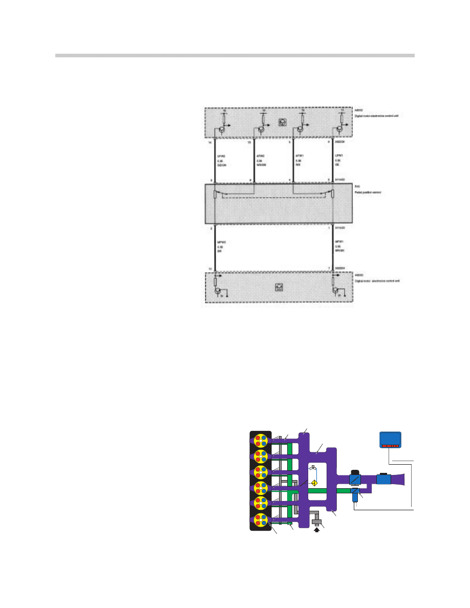
The MS45 PWG pedal position sensor consists of two separate Hall sensors with differ-
ent voltage characteristics and independent power supply (located in the accelerator pedal
module).
The pedal position sensor is mon-
itored by checking each individual
sensor circuit and comparing the
two pedal values. Monitoring is
active as soon as the sensors
receive voltage (KL15). The ECM
decides what operating mode the
pedal position sensor is to
assume.
• Mode = Pedal position sensor fully
operable.
• Mode 1 = Failure of one pedal position
position sensor (maximum engine speed
is limited).
• Mode 2 = Failure of both pedal position
sensors (engine speed limited to 1500
rpm).
The Idle Air Actuator is controlled by the ECM modulating the ground signals (PWM at
100 Hz) to the valve. By varying the duty cycle applied to the windings, the valve can be
progressively opened, or held steady to maintain the idle speed.
The ECM controls the Idle Air Actuator to supply the necessary air to maintain idle speed.
When acceleration is requested and the engine load is low (<15%), the actuator will also
supply the required air.
The basic functions of the idle speed control
are:
• Control the initial air quantity (air temp <0° C, EDK is simul-
taneously opened).
• Variable preset idle based on load and inputs.
• Monitor RPM range intake for each preset position.
• Vaccum Limitation
• Smooth out the transition from acceleration to decelera-
tion.
12550001
MDK
HFM
MAGNETIC
VALVE
VACUUM
UNIT
MS42.0
RAM TUBE
MAIN MAINIFOLD
RESONANCE TUBE
IDLE AIR CONTROL VALVE
(ZWD)
RESONANCE MANIFOLD
CRANKCASE VENTILATION
TURBULENCE MANIFOLD
TURBULENCE BORE 0:5.5mm
135500011

20
MS45 Air Management
Under certain engine operating parameters, the EDK throttle control and the Idle Air
Actuator are operated simultaneously. This includes all idling conditions and the transition
from off idle. As the request for load increases, the idle valve will remain open and the EDK
will supply any additional air volume required to meet the demand.
Backup Operation of Idle Air Actuator:
If a fault is detected with the Idle Air Actuator, the ECM will initiate failsafe measures
depending on the effect of the fault (increased air flow or decreased air flow). If there is a
fault in the Idle Air Actuator/circuit, the EDK will compensate to maintain idle speed. The
“Malfunction Indicator and/or EML” Light will be illuminated to inform the driver of a fault.
If the fault causes increased air flow (actuator failed open), VANOS and Knock Control are
deactivated which noticeably reduces engine performance.
The MS45 EDK Feedback Signal Monitoring/Backup Operation when a fault is detected in
the system is as follows:
• The EDK provides two separate signals from two integrated potentiometers (Pot 1 and Pot 2) representing the
exact position of the throttle plate.
• EDK Pot 1 provides the primary throttle plate position feedback. As a redundant safety feature, Pot 2 is continu-
ously cross checked with Pot 1 for signal plausibility.
• If plausibility errors are detected between Pot 1 and Pot 2, MS45 will calculated the inducted engine air mass
(from HFM signal) and only utilize the potentionmeter signal that closely matches the detected intake air mass.
- The MS 43.0 uses the air mass signaling as a “virtual potentiometer” (Pot 3) for a comparative source
to provides failsafe operation.
- If MS 43.0 cannot calculate a plausible conclusion from the monitored Pots (1 or 2 and virtual 3) the EDK
motor is switched off and fuel injection cut out is activated (Failsafe operation if not possible).
• The EDK is continuously monitored during all phases of engine operation. It is also briefly activated/adapted
when KL 15 is initially switched on as a “preflight check” to verify it’s mechanical integrity (no binding,
appropriate return spring tension, etc). This is accomplished by monitoring both the motor control amperate
and the reaction speed of the EDK feedback potentiometers. If faults are detected the EDK motor is switched
off and the fuel injection cut off is activated (failsafe operation is not possible). The engine does however
continue to run extremely rough at idle speed.
• When in emergency operation, the engine speed is always limited to 130 RPM by fuel injector cutout, and
activation of the “EML” light to alert the driver of a fault.
• When in emergency operation, the engine speed is always limited to 1300 RPM by fuel injector cutout, and
activation of the “EML” light to alert the driver of a fault.
• When a replacement EDK is installed, the MS45 adapts to the new component (required amperage draw for motor
control, feedback pot tolerance difference, etc). This occurs immediately after the next cycle of KL15 for approximately
30 seconds. During this period of adaptation, the maximum opening of the throttle plate is 25%.

21
MS45 Air Management
The Total Intake Air Flow Control is performed by the ECM simultaneously operating the
EDK throttle control and the Idle Air Actuator.
The ECM detects the driver’s request from the potentiometers/Hall Sensors monitoring the
accelerator pedal position. This value is added to the Idle Air control value and the total is
what the ECM uses for EDK activation. The ECM then controls the Idle Air Actuator to sat-
isfy the idle air “fill”. In addition, the EDK will also be activated = pre-control idle air charge.
Both of these functions are utilized to maintain idle RPM.
The EDK is electrically held at the idle speed position, and all of the intake air is drawn
through the Idle Air Actuator. Without a load on the engine (<15%), the EDK will not open
until the extreme upper RPM range. If the engine is under load (>15%), the Idle Air Actuator
is open and the EDK will also open.
The Hot-Film Air Mass Meter (HFM) varies voltage monitored by the ECM representing
the measured amount of intake air volume. This input is used by the ECM to determine the
amount of fuel to be injected.
The heated surface of the hot-film in the intake air stream is regulated by the ECM to a con-
stant temperature of 180º C above intake air temperature. The incoming air cools the film
and the ECM monitors the changing resistance which affects current flow through the cir-
cuit. The hot-film does not require a “clean burn”, it is self cleaning due to the high operat-
ing temperature for normal operation.
If this input is defective, a fault code will be set and the “Malfunction Indicator Light” will illu-
minate when the OBD II criteria is achieved. The ECM will maintain engine operation based
on the Throttle Position Sensors and Crankshaft Position/Engine Speed Sensor.
The Air Temperature signal allows the ECM to make a calculation of intake air tempera-
ture. The varying voltage input from the NTC sensor indicates the larger proportion of oxy-
gen found in cold air, as compared to less oxygen found in warmer air. The ECM will adjust
the amount of injected fuel because the quality of combustion depends on oxygen sensing
ratio.
The ignition timing is also affected by air temperature. If the intake air is hot the ECM retards
the base ignition timing to reduce the risk of detonation. If the intake air is cooler, the base
ignition timing will be advanced. The ECM uses this input as a determining factor for
Secondary Air Injection activation (covered in the Emissions section).
If this input is defective, a fault code will be set and the “Malfunction Indicator Light” will illu-
minate when the OBD II criteria is achieved. The ECM will maintain engine operation based
on the HFM and Engine Coolant Temperature sensor.
22
MS45 Air Management
Workshop Hints
Air Management
Unmetered air leaks can be misleading when diagnosing faults causing “Malfunction
Indicator Light”/driveability complaints.
Crankcase Ventilation System
A fault in this system can often “mislead” diagnosis. This type of fault can produce:
Please refer to the following Service Information Bulletins for details on the Crankcase
Ventilation System:
• Mixture/misfire detected codes
• Whistling noise
• Performance/driveability complaints
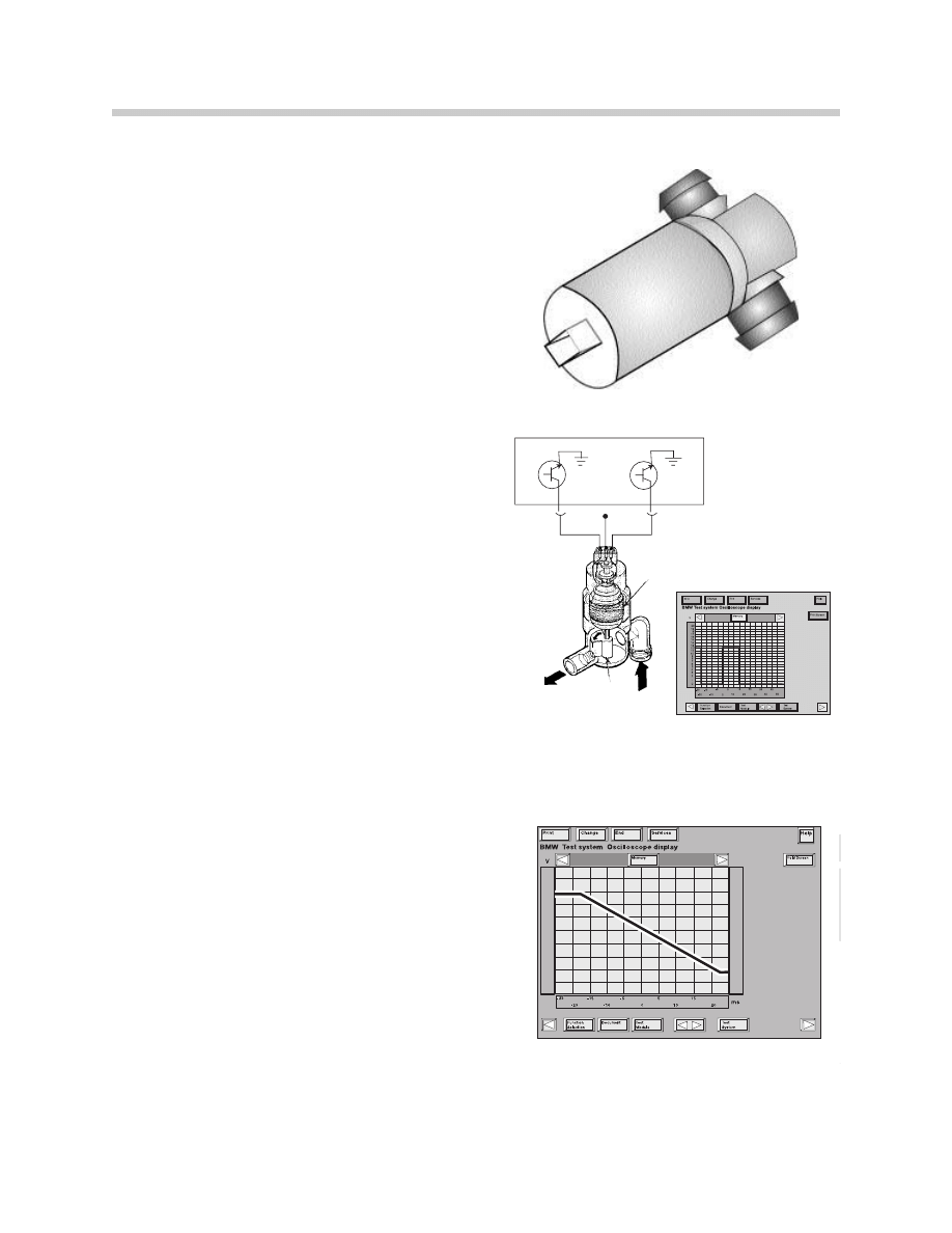
Throttle Position Sensors - Testing
The Throttle Position Sensors can be tested with the following methods:
• DISplus Status Page (appox. 0.5v. to 4.5v)
• DISplus Oscilloscope - Select from the Present measure-
ment which requires taking the measurement with the
ECM and the Universal Adapter connected to the cirucuit
as shown on the right).
13410067
23
MS45 Air Management
Idle Air Actuator Valve - Testing
• The Idle Air Actuator Valve and air circuit (passage ways)
should be checked for physical obstructions. Visually
inspect the sealing gasket, mounting bracket and air hose
clamps.
• The resistance of the valve winding should be checked
• The ECM ouput and Idle Speed Control Valve operation
can be tested by “Component Activation” on the DISplus/
GT1.
• The Pulse Width Modulation ground outputs from the ECM
can be tested using the DISplus/GT1 Oscillloscope.
• Consult Technical Data for specified idle speed.
NOTE: If the valve is blocked or contaminated,
an HFM fault code can also be present.
Air Temperature Signal - Testing
The HFM contains an integral air temperature
sensor. NTC sensors decrease in resistance as
the temperature rises and vice versa. The ECM
monitors the sensor voltage which varies as
temperature changes the resistance value. For
example, as temperature rises:
• Resistance through the sensor decreases.
• Voltage drop across the sensor decreases.
• Input signal voltage also decreases (5-0v).
This sensor should be tested using:
• DISplus/GT1 Status Page
• DISplus/GT1 Multimeter (ohms)
Two Winding
Rotary
Slide
B+
13550009
13550011
12550016
24
MS45 Air Management
Hot-Film Air Mass Sensor
This component is non-adjustable and tampering is not permitted. A faulty Hot-Film Air
Mass Sensor can produce the following complaints:
• Difficult To Restart When Engine Is Hot
• Engine Starts Then Stalls
• “Malfunction Indicator Light” Illuminated
• Engine Starts and Runs Only With
Accelerator Pedal Depressed
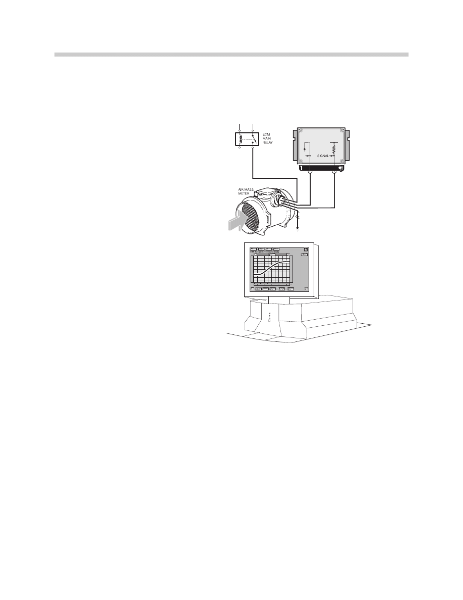
Testing: The Hot-Film Air Mass
Sensor can be tested with the fol-
lowing methods:
• DISplus/GT1 Fault Code and
Component Testing.
• DISplus/GT1 Status Page
• DISplus/GT1 Oscillloscope-which requires taking
the measurement with the ECM and the
Universal Adapter connected to the circuit
(engine running).
NOTE: Visually inspect the sensor for damaged, missing or blocked screens. The screens
affect air flow calibration. Also inspect the sealing rings where the sensor inserts in the air
filter housing and intake boot. Ensure the pin connections are tight.
16550010
25
MS45 Air Management
Tools and Equipment
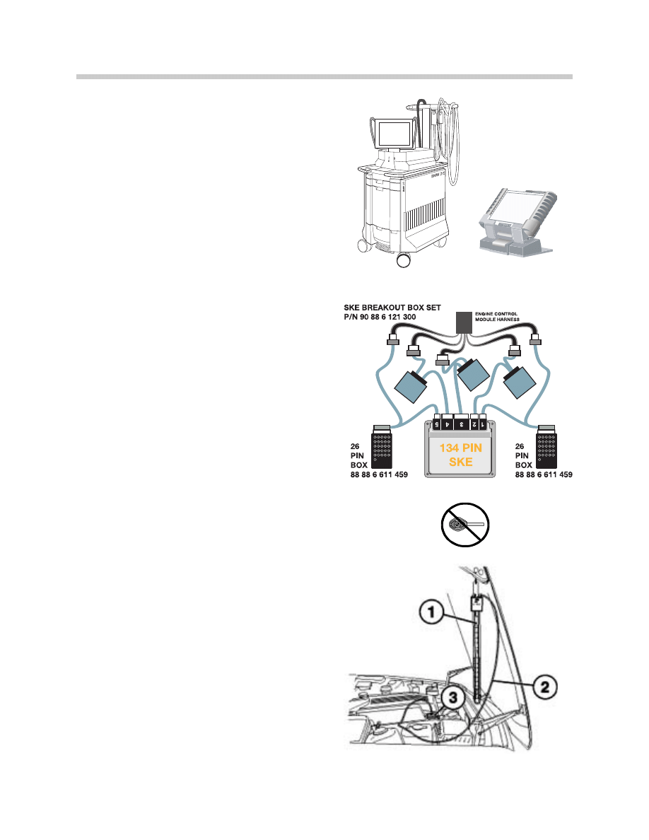
The DISplus/GT1 as well as a reputable hand
held multimeter can be used when testing
inputs/components.
It is best to make the checks at the ECM con-
nection, this method includes testing the wiring
harness.
The correct Universal Adapter for the MS45
application should be used (#90 88 6 121 300).
This will ensure the pin connectors and the har-
ness will not be damaged.
When installing the Universal Adapter to the
ECM (located in the Electronics Box in the
engine compartment), make sure the ignition is
switched off.
NOTE for MS45: Allow at least 3 minutes to
elapse after the key was set to the “OFF” posi-
tion before disconnecting the ECM/ TCM.
This will allow sufficient time to complete the
DM TL test. Voltage may be present (up to 3
minutes) causing damage to the ECM/TCM if
they are disconnected during this time period
(arcing).
The Slack Tube Manometer Test Tool (#99 00 0
001 410) should be used to troubleshoot
crankcase ventilation valves.
DISplus
GT-1
12550002
16550019
16550020
Document Outline
- Main Menu
- E85 Complete Vehicle
- E85 BodyShell
- M54 Engine
- MS45 DME Part 1
- MS45 DME Part 2
- MS45 DME Part 3
- MS45 DME Part 4
- E85 Driveline
- E85 Chassis Dynamics
- E85 Heating & Air Conditioning
- E85 Power Supply
- E85 Driver Information
- E85 Central Body Electronics
- E85 Communications
- E85 Updates
Wyszukiwarka
Podobne podstrony:
04c MS45 DME Part 4
2014 05 04 THE ESSENTIALS OF A HEALTHY FAMILY part 3
AlemĂŁo urgente! Para brasileiros 04 PartĂculas de ĂŞnfase
(sadryści vs rząd part 04) Rośnie liczba ofiar walk w Bagdadzie
part 04 bis
part 04
2014 05 04 THE ESSENTIALS OF A HEALTHY FAMILY part 3
part 04 bis
Wykład 04
04 22 PAROTITE EPIDEMICA
04 Zabezpieczenia silnikówid 5252 ppt
GbpUsd analysis for July 06 Part 1
Wyklad 04
Wyklad 04 2014 2015
~$Production Of Speech Part 2
04 WdK
więcej podobnych podstron