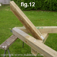
Huśtawka


Introduction (scroll down for Plans)
0x01 graphic

The footprint (ground area) of this swing seat support frame is 2700mm (9ft) x 2100mm (7ft).
The overall height is 2025mm (81").
0x01 graphic

Although this support frame is purpose-made for a particular swing seat, it can also be used to support numerous other utilities such as swings or maybe a glide-ride, and is even capable of accommodating certain types of gym equipment.
0x01 graphic

It is a very solid frame and basically consists of two end A-frames designed to minimize front and back movement, a beam which sits on top and two braces designed to minimize sideways movement.
0x01 graphic

The lumber used in this project is 100 by 100 (4x4) stock, which means that the lumber is 100 millimeters (4") wide by 100 millimeters (4") thick. This is a very common stock size and should be readily obtainable from most lumber or building supply yards. If you prefer to use smooth lumber as opposed to rough, that generally means that the wood has been planed or dressed and therefore the size of the lumber will be slightly smaller, but that does not matter. Most important is that the lumber is suitable for outside use and strong enough for the job, which basically means the stock should be reasonably straight-grained and contain very few knots - definitely no big knots. Your local lumber supplier will be able to advise you on the most suitable types of lumber available and also what safety precautions might need to be taken while working with any particular type of lumber. For example, when working with treated lumber you will need to wear appropriate clothing, gloves and mask while cutting or shaving and certain waste disposal and clean up rules must be adhered to.
0x01 graphic

Below are the plans followed by a description of each member.
0x01 graphic

0x01 graphic

0x01 graphic

Individual pieces
0x01 graphic

[a] A-frame leg 100x100 (4x4) stock suitable for exterior use. Cut 4 pieces to length as shown above. Angle cut each end 26.6 degrees off square. There is more information on how to mark and cut the angles in the instruction page.
0x01 graphic

[b] Horizontal brace 100x100 (4x4) stock suitable for exterior use. Cut two pieces to length as shown above. Angle cut each end 26.6 degrees off square.
0x01 graphic

[c] Diagonal brace 100x100 (4x4) stock suitable for exterior use. Cut two pieces to length as shown above. Angle cut each end 45 degrees off square.
0x01 graphic

[d] Beam 100x100 (4x4) stock suitable for exterior use. Cut one piece to length as shown above.

Materials list and fastening detail
You will need....
All the lumber listed below is 100x100 (4x4) stock and should be suitable for exterior use.
0x01 graphic
4 pieces at 2400 (8ft) long. Cut the legs from this.
0x01 graphic
1 piece at 2700 (9ft) long. For the beam.
0x01 graphic
1 piece at 3000 (10ft) long. Cut the braces from this.
0x01 graphic

You will also need....
0x01 graphic
Galvanized nail-on plate. 2 at 100x100 (4x4); 10 at 125x50 (2x5); 2 at 150x50 (2x6).
All of the above can be cut out of bigger size plates if necessary.
0x01 graphic
Four 12mm (1/2") galvanized bolts 220mm (8 3/4") long.
0x01 graphic
Two 10mm (3/8") galvanized bolts 150mm (6") long. To hang the swing seat chain off.
0x01 graphic
140 50mm (2") flathead galvanized nails.
0x01 graphic
A handful of 100mm (4") galvanized nails.

Fastening detail
Use galvanized nail-on plate or similar, to securely fasten all the frame members to each other.
0x01 graphic

The sizes listed above can be cut out of larger pieces with a pair of tin snips or other type of plate cutters. See
fig.1 and fig.2.
0x01 graphic

Fix the plates as shown in
fig.3 with five 50mm (2") flathead galvanized nails into each member. That is, ten nails for each nail-on plate.

Making two galvanized U-shaped nail-on plates
The top of each "A" frame requires a U-shaped nail-on plate as shown in
fig.6.
0x01 graphic

Each U-shaped plate can be made by clamping a 150x50 (2x6) nail-on plate between two 100x100 (4x4) pieces of lumber (
fig.4) and then by hammering down the parts that jut out, as shown in fig.5.
0x01 graphic

Each U-shaped plate can then be fixed to the top of the two "A" frames (as shown in
fig.6) with 50mm (2") flathead galvanized nails.

Other Fastening
Use 12mm (1/2") galvanized bolts 220mm (8 3/4") long to fasten the horizontal braces to the legs.
0x01 graphic

Use 100mm (4") galvanized nails to secure members together where needed.
0x01 graphic

Use two 10mm (3/8") galvanized bolts 150mm (6") long to hang the swing seat chain off.


0x01 graphic

0x01 graphic

0x01 graphic

0x01 graphic

0x01 graphic

0x01 graphic

Step 1. Cut all the members
Cut all the members to length and with the angle cuts as described in the
Individual Pieces (and also as shown in the Plans on page one).
0x01 graphic
All the lumber used is 100x100 (4x4) stock and all the angle cuts are 26.6 degrees off square except for the two diagonal braces which are cut at 45 degrees both ends.
0x01 graphic
There are directions below on how to make the angles if you do not have any type of angle marking tool.
0x01 graphic
fig.7 shows the cut lines at the top of the legs. fig. 9 below shows how to mark the cut lines at the top of the legs and fig.8 shows how to mark the cut lines at the bottom of the legs

0x08 graphic
How to mark the 26.6° cut line at the bottom of the legs
(1) Square a line from x to y (fig.8) across the leg.
0x01 graphic
(2) Mark point z along the leg. The distance from z to x should be exactly half of the distance from x to y.
For example: if the distance from
x to y is 100mm (4"), then the distance from z to x should be 50mm (2").
0x01 graphic
(3) Draw a line from z to y. This is the cut line and is 26.6° off square.

0x08 graphic
How to mark the 26.6° cut lines at the top of the legs
(1) Square a line from x to y (fig.8) across the leg.
0x01 graphic
(2) Mark point z along the leg. The distance from z to x should be exactly half of the distance as that from x to y.
For example: if the distance from
x to y is 100mm (4"), then the distance from z to x should be 50mm (2").
0x01 graphic
(3) Draw a line from z to y.
0x01 graphic
(4) Mark point u 50mm (2") from z along line zy. See fig.9.
0x01 graphic
(5) Square a line from u to v (fig.9) across the leg.
0x01 graphic
(6) Mark point w. The distance from w to v should be exactly twice the distance as that from u to v. 0x01 graphic

(7) Draw a line from w to u. This line should be at right angles to line zy.

0x08 graphic
Step 2. Lay the legs on stools
Lay a pair of legs out in "A" frame position on three stools or supports. See
fig.10.
0x01 graphic

Position the horizontal brace on top of the two legs.
0x01 graphic

The bottom of the horizontal brace should be 600mm (2ft) down from the top of the "A" frame.
0x01 graphic

Refer to the
plans on page one for more positioning dimensions.

0x08 graphic
Step 3. Fix the "A" frame
When the "A" frame members (two legs and one horizontal brace) are correctly positioned, they can then be secured together.
0x01 graphic

Use a 100x100 (4x4) nail-on plate where the two legs join and fix a U-shaped nail-on plate to the top of the "A" frame. See
fig.11. Also see making a U-shaped nail-on plate
0x01 graphic

Use galvanized bolts to fix the horizontal brace to the legs, one at each meeting.
0x01 graphic

Hold the horizontal brace to the legs with a couple of clamps prior to drilling the bolt holes.

0x08 graphic
Step 4. Add a brace
Fasten a diagonal brace to the horizontal brace of the "A" frame as shown in
fig.12.
0x01 graphic

Secure with a couple of 100mm (4") galvanized nails and a nail-on plate.
0x01 graphic

Next make up the second "A" frame BUT WITHOUT ADDING THE DIAGONAL BRACE, as that brace will be added when the (almost) complete frame is standing upright.

0x08 graphic
Fix the beam to an "A" frame
Tilt an "A" frame against the beam in a sort of a 3-sided pyramid shape so that the beam, "A" frame top and diagonal brace all align.
0x01 graphic

Ensure that the top end of the beam is overhanging the "A" frame by 100mm (4") and that the beam is at right angles (90°) to the "A" frame. Refer to the
plan if necessary.
0x01 graphic

Then, fix the beam to the "A" frame with galvanized nail-on plates.
See fastening details and fig.13.

0x08 graphic
Stand the frame upright
Stand the frame upright and balance the beam on the top of the other "A" frame with the beam overhanging 100mm (4"). See
fig.14.
0x01 graphic

Ensure that the beam is at right angles (90°) to the "A" frame and then secure by nailing through the U-shaped nail-on bracket into the beam.

0x08 graphic
Add a brace and make secure
Add the diagonal brace and fix in place with 100mm (4") galvanized nails and nail-on plates. See
fig.15.
0x01 graphic

For further reference on fixing and nail-on plates go to
fastening details

0x08 graphic
Attach the seat chain
Now it's just simply a matter of hanging the swing seat.
0x01 graphic

Insert two 150mm (6") bolts through the beam above the swing seat, one at each end.
0x01 graphic

The bolts will protrude above the top of the beam by about 50mm (2").
A chain link can then be fitted over each bolt shank on top of the beam and held in place with washers and nuts.
See fig.16.
0x01 graphic

For plans and instructions on how to make a swing seat
click here

The Porch Swing.
This seat has an adjustable seat-back which angles back to give varying degrees of comfort depending on whether or not you want to sit up straight or lie back a little.
As with other Buildeazy projects, it designed with the home handyman or DIYer in mind. All joins are secured with bolts and/or screws and nails. Because of this, the project only requires the most basic of tools to undertake a professional job.

A bit about the lumber.
All dimensions are in both millimeters and inches. The inch dimensions are in brackets ( ).
0x01 graphic

There are two different types of lumber used for this project. 90 x 35 (1-1/2" x 3-1/2") treated pine for the frame and 90 x 20 (3/4" x 3-1/2") hardwood for the seat slats and back slats. Also a small amount of 145 x 20 (3/4" x 5-3/4") treated pine for the arm rest.
0x01 graphic
If the sizes vary in your area, just make allowances accordingly.
0x01 graphic
The 45 x 35 (1-1/2" x 1-3/4") pieces required are from 90 x 35 (1-1/2" x 3-3/4") stock ripped (sawn down lengthwise) in half.
Any other smaller members that are required can also be cut from standard stock.
Hardware.
As well as the lumber in the list below, you will also need...
0x01 graphic
Two 3600mm (12ft) lengths of galvanized chain
0x01 graphic
10 galvanized coach (carriage) bolts 10mm (3/8") x 120mm (5") long.
0x01 graphic
A handful of 100mm (4") nails.
0x01 graphic
A few 75mm (3") nails to hold the two end frame members together while drilling and bolting.
0x01 graphic
92 wood screws approx 35mm (1-1/2") long for the seat slats, back slats and arm rests.
The cutting list
All dimensions are in both millimeters and (inches)
0x01 graphic
0x01 graphic

The Instructions

0x08 graphic
Make up the two end frames.
Cut the members (a), (b), (d), (e), (f), (h), and (i) to the dimensions as shown in the lumber list in the
previous page.
Make up the two end frames using the drawings below as a guide. Note that the inner seat frame ends (b) are a different width than the outer seat frame ends (a) by 20mm (3/4") which is the thickness of the seat slats.
First nail and then bolt the horizontal members (a), (b), (f) to the vertical members (d) and (e) with 10mm (3/8") coach (carriage) bolts. The spacers (h) and (i) can be fixed with screws.


0x01 graphic

Make up the seat frame.
Cut the members (c) and (j) to the dimensions as shown in the lumber list in the
previous page.
Nail the front and rear seat frame members(j) to the seat frame end members (a) and (b). Nail in place the two seat frame intermediate members (c) ensuring that they are 20mm (3/4") below the top edge of the front and rear seat frame members (j).

0x01 graphic

0x01 graphic

The back slat support.
Cut member (k) to the dimension as shown in the lumber list in the
previous page.
Round each end. You can use a dinner plate, paint tin or any other circular object as a template to draw a curve.
Bolt the back slat support (k) to the two rear vertical arm supports (e).

0x01 graphic

Fix the seat slats in place.
Place the seat slats in place spread evenly within the seat frame. Members (n) and (m) will need to be checked (cut) out at each end to allow for the chain cavity and vertical arm supports (d) and (e). (See diagram).
Screw the seat slats to the seat frame members (b) and (c). Pre-drill screw holes in the slats slightly bigger that the screw shank.

0x01 graphic

The Instructions

Fix the back slats in place and mark for cutting.

0x01 graphic
 0x01 graphic


Temporarily nail a straight edge to the bottom half of the rear seat frame (j) so the back slats will have something to sit on while they are being fixed in place. Spread the back slats (p) out evenly between the two end frames and fix to the back slat support (k) and the rear seat frame member (j) with screws. Pre-drill screw holes first through the back slats.
When the back slats are fixed in place, you can draw a pattern of your choice at the top of the back slats. Cut with a jig-saw if the pattern has curved lines or a handsaw will do if the pattern only consists of straight lines.

Fit the arm rest.
Cut the arm rest (g) to fit around the rear vertical arm support (e) and fix with screws to the horizontal arm supports (f).
Make holes in the appropriate places for the chain cavities.

0x01 graphic

0x08 graphic
Thread the chain.
Thread the chain through the holes in the arm rests down through the cavities at the bottom of the end frames and back up.
The holes and cavities should be big enough so that the chain can be pulled through freely.
When the seat is held off the ground by the chains (more about that next page), the seat angle can be easily adjusted and locked in place by inserting a "chain stop" through one of the chain link holes just above the front arm rest (g) hole. A "chain stop" can be a small bolt, piece of rod or anything that can fit through a chain link hole and stop the chain from slipping around the end frames.
When you want to re-adjust the seat angle, simply take out the "chain stop", adjust the angle and lock in place again by putting the "chain stop" back.

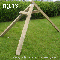
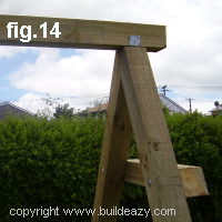
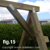
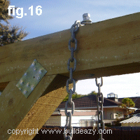
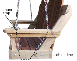
Supporting the swing.
Hang the swing so the seat is approx 400 (16") off the ground. The builder is responsible for ensuring that swing is supported adequately to take the weight of the swing as well as the people that might occupy it.
Have fun!

0x01 graphic

Author: Les Kenny
Editor: Maree Anderson


Wyszukiwarka

Podobne podstrony:
mechanika kinematyka predkosc poczatkowa hustawki
proces produkcji hustawki drewn Nieznany
27 I Bukraba Rylska, Migracje zarobkowe, od obieżyświata do ludzi na huśtawce
Huśtawka emocjonalna, HUŚTAWKA EMOCJI
huśtawka z niedźwiedziem
Bulimia. Huśtawka na wadze, anoreksja ,bulimia, ortoreksja ... -zaburzenia odżywiania
78 Nw 07 Hustawka ogrodowa
Hustawka Emocji u Kobiet
hustawka
dwoje na hustawce
huśtawka z niedźwiedziem 2
Jaźwińska,Okulski Ludzie na huśtawce,Migracje między peryferiami Polski i zachodu rozdz 2,4,
Huśtawka ganku, Stolarstwo
71 NW 08 Lezak hustawka
chlopiec na huśtawce
Reagenty na huśtawce czyli rzecz o równowadze chemicznej
kaczka na huśtawce powiększenie

więcej podobnych podstron