Introducing...
~ The Islander ~
A 7 Watt FM Transmitter
...updated as of July 25th, 2003
On July 25th, I received a letter from a dear friend named Todor. After 4 months of intense pursuit, he finally made 'The Islander' come to life! Here is a portion of his letter...
Yes, yes, yes !!! ... The transmitter is working, it`s working !!! ... Yes, Patrick, finally, this time I am more than sure, that 2SC1971 stage is working: 1. The transistor gets very HOT (I can`t even touch him!) 2. The ampermeter on my DC supply shows a gain of approx. 0,5 A. 3. I tried it with your RF probe (the watt-meter), and it shows me 5,8 watts. Finally...
You may want to read Sir Todor's whole story, from beginning to end, of his challenges with the project. Once read, you may come back to this webpage and continue to read on the construction on this most challenging FM Transmitter. To read Sir Todor's story, just click HERE.
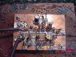
Just click on the above picture for a larger view. My design of the Islander came after one year of intense experimentation. Formally, the last stage had 3 more variable capacitors...but I took them out and adjusted their respective coils to a preset form...thereby eliminating of having to adjust 5 variable capacitors. My PCB design is a 'no hole' component mount. The PCB does look rather worn...that is because much experimentation (changeouts/omissions/add-ons) was done to achieve a more functional unit. All the area around the circuitry has a ground plane (front and back). The copper layout is on the 'same' side as the components. Just click on the above picture for a larger view.
In viewing the unit, please note the way the PCB is made... this is extremely important! But this will be mentioned further down the webpage. Also notice the upper coax...that went to my dipole antenna. The lower coax...which was about 9 inches in length, went to my electret mic. Since the tank circuit was NOT shielded, putting my head too close to the electret mic (mic was previously soldered directly on the PCB), I would offset the 'preset' frequency. So the nine inches of coax made a very stable unit when talking into the microphone. The two upper wires on the right were my 'hot' side and the lower right wire (in red) was my ground. Arrangement of circuitry in the VHF arena is indeed important. My sole reason for showing you this picture is again, to give you an idea of what the 'no hole' design looks like. Also, do make sure, when using your 12+ volt power supply...that you keep it as close to the circuitry as possible.
This transmitter's ouput power is 7 watts. This device must only be used in accordance with your country's applicable laws concerning radio frequency transmissions... |
The 7-Watt FM Transmitter Schematic
|
D2* - This rectifier is a 1N5401, which cross-references to an NTE5401. I have also used a 1N4001/2/3/4/5 and it has seemed to work just as well.
TRANSISTORS
Q1 NPN MPS3904 or 2N3904 Transistor |
Q2 PNP MPS2907 2N2907 Transistor |
Q3 NPN 2N2222A or MPS2222A Transistor |
Q4 NTE342 (cross reference 2SC1971) |
Mouser Electronics in the USA carries all of the transistors shown above. The picture below shows the pricing on the NTE342 and toll-free phone number for ordering the components you may need. . To find their website homepage, just go to the Yahoo Homepage and type in the keywords...Mouser Electronics.
|
COILS/DIODE
L1 & L2 are air-core coils...8mm diameter...3 turn wrap...1 turn tap (L1 is tapped one full turn from the diode side (D1) of the coil...L2 is tapped one full turn from the collector side of the MPS222A transistor) using un-insulated 18 gauge solid wire. Use may use a 5/16" standard threaded bolt to wrap the wire on. It fits perfect. then back out of bolt. Do not stretch or squeeze these coils after they have been backed out of the threaded bolt. For a detailed description on how I made my 'tapped' air-core coils, please CLICK HERE. |
L3 & L6 are air-core coils...5mm diameter...3 turn wrap...18 gauge solid wire...use a 1/4" standard threaded bolt to wrap the wire on. It fits perfect, then back out of bolt. NOTE: L3 and L6 are very critical coils. You will need to adjust (sqeeze or stretch) both of these coils to obtain maximum voltage output. Experiment with these two important coils...after you have tuned (L1 and L2) your transmitter to a specific frequency. |
L4 is a VK-200 choke (If omitted, output power is reduced by 25%) Mouser Electronics here in the USA sells this component...it sells for less than one dolar. |
L5 is an air-core coil...5mm diameter...11 turn wrap...18 gauge solid wire...use a 1/4" standard threaded bolt to wrap the wire on. It fits perfect, then back out of bolt. Sqeeze all the wraps real close...but make sure none are touching each other. |
D2 is an NTE5801. I have also used a 1N4001, 1N4002, 1N4003, 1N4004, 1N4005 in place of the original rectifier, with no complications. |
NOTE: Squeeeze or stretch L3 & L6 to achieve maximum output wattage. I also took off the insulation on the 18 gauge wire to make the air-core coils. |
...getting started
Below are the construction plans for the PCB layout. The routing of the PCB in the template below, is exactly as the one you see in the above digital picture. I strongly suggest you go with this routing, as it has worked fine for me. Should you sway from this routing design, I would have no way to help you in finding out what the problem should be, if the unit does not function. In the VHF band arena, any detour from the said instructions could possibly warrant a 'no-go' in the end! Be very explicit and detailed when it comes to making this routing design.
PCB Routing Template
|
Figure I
Notice the orange areas and notice the white areas. The orange areas is where you will want to 'keep' the copper on the PCB. The white areas is where you want to 'take away' the copper on the PCB. This is called a 'hot island' method of making a PCB. There are no holes to be drilled, except for the NTE342 and for mounting and ground plane purposes.
First thing to do is to print out this template in black & white. Then measure the width and length for an exact measurement of 78mm X 107mm. This is crucial. If the printout of the template does not come out to these exact measurements, send the drawing to a graphics program and sqeeze and/or stretch the drawing until proper measurements are made. Once that is done, you can now make your PCB to the exact size of the drawing. Once this is done, you may proceed to make the PCB. After you have finished making the PCB, refer to the next section of how the NTE342 is positioned onto the PCB...together with the 4 mounting holes and the one continuity hole.
Placement of the 342NTE Transistor
Front of PCB
|
Figure II
The above drawing is what your PCB should look like prior to soldering all of the components on the PCB. Notice the four mounting holes that are required. They are on each corner of the PCB above. Drill these 4 holes now. Next will be the positioning of the NTE342 Power Transistor. Hole #1 is for the securement of the transistor itself. The transistor will actually be on the 'backside' of the PCB. The copper, on the backside of the PCB, serves as a large heatsink for the transistor. When you purchase your transistor, there will be a hole in the top portion of the metal tab. This is where you will place a machine screw and nut. Hole #2 is where the COLLECTOR leg of the transistor will go and Hole #3 is where the BASE leg of the transistor will go. Since the transistor will be positioned on the backside of the PCB, run your two legs through the hole from the backside...coming out to the frontside. Once they are in place, both needs to be soldered (on the frontside of the PCB) on each of their respective 'hot islands'. Now let's look at the backside of the PCB...
Back of PCB
|
Figure III
This is where the transistor will be located...on the backside of the PCB. The left leg is the BASE leg. The right leg is the COLLECTOR leg and the middle leg is the EMITTER leg. The EMITTER leg is soldered directly to the backside of the PCB, which is the GROUND. The small white area is the area where there is 'no copper'. This is needed to keep the two outside legs from touching GROUND. Before tightening up the transistor with the machine screw and nut, be sure to use that white creamy agent between the PCB and the metal tap before tightening up the screw...this white cream is used to aid in the transfer of heat from the metal tab of the transistor to the copper on the back side of the PCB.
Component Placement
|
[You should print this drawing out (in black and white) to have a copy on hand while soldering components]
Component Placement (cont'd)
1. Electret Microphone |
17. 100pF Ceramic Disk Capacitor |
33. 5-30pF Variable Capacitor |
2. 1uF/50v Electrolytic Capacitor |
18. VK200 Choke |
34. 1N914 Diode (Observe Polarity) |
3. 4.7K Carbon 1/2 Watt Resistor |
19. Coil |
35. 1uF/50v Electrolytic Capacitor |
4. 47K Carbon 1/2 Watt Resistor |
20. 56pF Ceramic Disk Capacitor |
36. #36 is omitted on drawing. |
5. 5.6K Carbon 1/2 Watt Resistor |
21. #21 is omitted on drawing. |
37. 2N2907 or MPS2907 (PNP) Transistor |
6. Antenna Input (50 Ohms Impedance) |
22. 39pF Ceramic Disk Capacitor |
38. .001 Ceramaic Disk Capacitor |
7. .001uF Ceramic Disk Capacitor |
23. 22pF Ceramic Disk Capacitor |
39. 4.7K Carbon 1/2 Watt Resistor |
8. 100 Ohm Carbon 1/2 Watt Rersistor |
24.22pF Ceramic Disk Capacitor |
40. 1uF/50v Electrolytic Capacitor |
9. 1.2K Carbon 1/2 Watt Resistor |
25. 120pF Ceramic Disk Capacitor |
41. 2N3904 or MPS3904 (NPN) Transistor |
10. 24pF Ceramic Disk Capacitor |
26. 5-30 Variable Capacitor |
42. 22K Ohm Carbon 1/2 Watt Resistor |
11. 24pF Ceramic Disk Capacitor |
27. Coil |
43. 270 Ohm Carbon 1/2 Watt Resistor |
12. Coil |
28. .001 Ceramic Disk Capacitor |
44. 5.6K Ohm Carbon 1/2 Watt Resistor |
13. .1uF Ceramic Disk Capacitor |
29. 22 Ohm Carbon 1/2 Watt Resistor |
45. Coil |
14. 470uF/50v Electrolytic Capacitor |
30. 2N2222A or MPS2222A (NPN) Transistor |
46. Refer to 'Component Placement' drawing |
15. NTE5801 Rectifier (also see text) |
31. Coil |
|
16. NTE342 or 2SC1971 (NPN) Power Transistor (See Text) |
32. 5.6pF Ceramic Disk Capacitor |
|
The Story behind the Transmitter
Above is the schematic for the 7-Watt FM Transmitter. It was originally a 200mW unit, without the universal power stage added. Together with the power amp (NTE342), it then became a 7-watt unit. I used this transmitter with a open half-wave dipole antenna in a vertical position 50 feet above ground. Together with about 70 feet of coax, this transmitter delivered great audio at a distance of 10 miles...overall distance was 17 miles, but the audio signal was weak.. I had no equipment, other than a watt meter (to measure it's power) and a digital FM tuner (with a 5-LED Signal Strength Bargraph display) to use as capturing the main oscillating frequency, which was right at 87.5 MHz. This circuit worked well for me, as I had experimented with it for nearly a year. Of course, one would be better off with more equipment than I have had...to capture the main oscillating frequency. That was, by far, one of the hardest things to capture. It was thru trial and error, with the FM tuner, in finally finding out how to grab the right frequency. When I finally did get used to finding out where my 'main' frequency was, the unit performed extremely well. Like I had said above, right at 10 miles, the unit was at it's best...giving clear audible audio into the speakers of my car. With the transmitting antenna at 50 feet above ground, I decided to see how well I could receive the transmitter signal from an overpass than is exactly 15 miles from the transmitter. When I got to the top of the overpass in my car , the audio signal came in as 'clear as a bell'. I now undersand what is meant when one says FM signal travels best in a line of sight. Well, being on that overpass, if I had a strong telescope with me, I am sure I could see the 50 foot antenna in my oak tree. So with the overpass being right around 50 feet in height also, the transmitter surpassed my judgement call on its' signal. I surrender this circuit to anyone who likes to experiment in things like this...
Getting It Up & Running
The best possible help I could give one in making this FM unit function well, is to have a homemade watt meter and a homemade Field Strength Meter available. Together with a DVM, these two homemade devices can aid you in fine-tuning the unit and also giving you an rough idea of how much wattage you are putting out. If you can get hold of an FM tuner, with a bar-graph LED Signal Strength readout, this can aid in finding the 'main' transmitting frequency...
The three test devices above is what I had used in the complete makings of the transmitter. I had nothing else. A lot of 'trials & errors' came into play when I had to limit myself in tuning the transmitter/adjustment of coils/catching the main osciallating frequency...with just three pieces of test equipment mentioned above But it did work out well in the end. I do believe...
...necessity is the mother of invention.
If there is any questions or concerns regarding this project, do not hesitate to send me a letter. I am here to help in any way that I can...
This webpage has just been updated...to make it even easier to understand the complete makings of the unit. Should you happen to spot something that looks 'not quite right' or something that I might have not explained in more detail...do drop me a line and I will get back with you on it.
...your friend, Patrick
You are our website guest number 2353 since June 11th 2002 |
Wyszukiwarka
Podobne podstrony:
High Power Mini FM Transmitter Shematics (1Km range)
Microphone FM Transmitter
Diy Kit 51 Miniature Fm Transmitter
słobodzian,pracowania problemowa P, transmiter FM
2 Transistor FM Voice Transmitter
FM VHF Stereo Transmitter
Transmisja WAP
Sieci media transmisyjne
Media Transmisyjne
fm 2
FM zaocz W7 8 pp
AM FM SSB Empfänger Teil 1
energoefekt artykul transmisja danych GPRS NiS[1]
Elektronik Inteligentny dom Transmisja Danych Siecia id 158
FM listy id 178271 Nieznany
Lista odpowiednikĂłw FM Group
FEDERICO MAHORA-katalog, PRASA, FM Group
3 - Droga do Sukcesu - strona druga, fm, 45 sekundowa prezentacja, sekrety, teczka fm
więcej podobnych podstron