Chapter 53
THE EFFECT OF THE VELOCITY OF AIR FLOWING THROUGH
AN INTERMEDIARY MEMBRANE COOLER ON ITS THERMAL POWER
B. Nowak |
K. Filek |
University of Mining and Metallurgy Kraków, Poland |
S. Nawrat J. Roszkowski University of Mining and Metallurgy Kraków, Poland |
ABSTRACT
The article deals with the effect of the velocity of air cooled by an intermediary membrane, cooler, on its thermal efficiency and the resultant efficiency of the fan-cooler system; in considering this matter the cooling power and air-drying power have been differentiated. A significant impact on these values is the width of the cooler's zones: a zone of dry air cooling and a zone of vapour condensation cooling. The study is also concerned with the effect of air velocity on the width of these zones. In their considerations, the authors have taken into account the effect of velocity on heat exchange, examining both a parallel and counterflow cooler arrangement. It has been assumed that changes in air flow velocity result from changes in the rotational speed of the fan's impeller, installed on the cooler's inlet side. In calculations the authors used algebraic equations derived from mathematical space-time models of the changes in temperature and humidity of the cooled air and the temperature of heat exchanger and cooling air, taking place in water membrane air coolers. These models are based on enthalpy balances of air, water and membrane and on the balance of water vapour mass; they do not make use of mean values that have been commonly applied to date. The exemplary results of the theoretical calculations have been presented in a graphical form.
KEYWORDS
Mining aerology, work comfort, air-conditioning, air cooling, membrane water coolers
INTRODUCTION
The basic criterion for the efficiency of air coolers is a range of changes observed in its temperature and humidity at the point of cooling, resulting from the real thermal power of a heat exchanger. Differences in the thermal capacity of air coolers: nominal (rated) power values as defined by the producer, and the actual values obtained from thermal balances, result chiefly from cooled air parameters on the cooler inlet, which differ from the assumed values; hence the temperature, humidity and flow velocity, as well as cooling water parameters - temperature and flow intensity, are different. For this reason the article is concerned with the effect of the velocity of air flowing through a parallel and counterflow cooler arrangement of intermediate acting coolers on their thermal capacity and the power of the fan-cooler system; we have seperated the power connected with changes in the sensible heat of the air and the water vapour contained in this air, as well as the latent heat of condensation of water vapour. The results of characteristic calculations are presented graphically. The calculations were made for two different values of specific air humidity, cooled by a Polish GCCP-115 type cooler, operating in co-ordination with a booster fan of WLE-1004A type.
THERMAL POWER OF AIR COOLER
AND FAN - COOLER SYSTEM
The power of the cooler alone can be calculated from the following relationship
![]()
(1)
where:
M - stream of dry air mass [kg/s],
h2 - specific enthalpy of air at the cooler inlet [J/kg],
h3 - specific enthalpy of air at the cooler outlet [J/kg],
hw - specific enthalpy of water refluxed from air [J/kg].
![]()
(2)
![]()
(3)
where:
cp - the specific heat at of dry air at steady pressure [J/(kgK)],
cw - the specific heat of water vapour at steady pressure [J/(kgK)],
rp - latent heat of evaporation of water [J/kg],
t2, x2 - respectively the temperature [oC] and specific humidity [kg of H2O vapour/kg of dry air] of air at the cooler inlet,
t3, x3 - respectively the temperature [oC] and specific humidity [kg of H2O vapour/kg of dry air] of air at the cooler outlet.
Assuming the temperature of the refluxed water to be equal to the temperature of the cooled air, we can write
![]()
(4)
where cc - the specific heat of water[J/(kg K)].
The formula (1) after considering (2) and (3) is as follows
![]()
(5)
Cooler power may be written down as
![]()
(6)
where:
![]()
(7)
![]()
(8)
Power marked as Ncs is related to a change of the air's sensible heat and the latent heat of water vapour contained in the air; it manifests itself as an air temperature decrease. On the other hand, power Ncw is connected with the process of vapour condensation and manifests itself in the drop in specific humidity. This component represents enthalpy connected with latent heat of water vapour condensation and the enthalpy of refluxed water, which is relatively insignificant in comparison with the former. Power Ncs may be called air cooling power, and power Ncw - air drying power.
The flow of air through a cooler is induced by a fan mounted on the cooler's inlet side. It heats the inflowing air from temperature t1 to temperature t2, without changing its specific humidity. This makes thermal power Nu of the whole fan/cooler system lower than the power N0 of the cooler alone.
The resultant power of Nu system may be calculated from the formula
![]()
(9)
where h1 - specific enthalpy of air at the fan inlet [J/kg], equal
![]()
(10)
After substitutions we obtain
![]()
(11)
where Δtwent - increase in temperature of air in cooler [°C].
![]()
(12)
When conditions in the cooler are steady (constant M, x1, Δtwent) the power of the fan/cooler system differs from that of the cooler alone by a constant value.
The separated components of the power Nc, i.e. the cooling power Nc and the drying power Ncw have their counterparts in the power of system Nu, which were determined as Nus and Nuw. They can be calculated from (13) i (14). As it appears, the overall increase in the enthalpy of the air in the fan is connected with sensible heat.
![]()
(13)
![]()
(14)
![]()
(15)
Since the fan heats the air that is destined to be cooled, it is important what type of fan will be used in conjunction with a given type of a cooler. In the case of a fan whose effective power is too small, the air flow velocity is too low and the capacity of the cooler is not fully utilised, whilst a fan with excessive power may cause such a large increase in the air temperature that it considerably cancels the positive effect of the cooler's operation to a considerable extent.
THERMODYNAMICAL MODEL OF COOLER
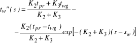
The determining of Nc, Ncs, Ncw, Nu, Nus i Nuw requires knowledge of the temperature and specific humidity of the cooled air as it leaves the cooler. For their theoretical calculation mathematical models are used, which have been presented in detail in the paper (Filek, et. al., 1999 a). The models are a simplified version of the mathematical descriptions presented in (Holesz, 1997; Filek, et. al., 1999 b; Filek and Nowak, 1999), obtained from balances of cooled air enthalpies, the membrane of a heat exchanger and cooling water as well as a balance of water vapour mass in the air. For a steady state, after assuming the simplifications mentioned in (Filek, et. al., 1999 a) and distinguishing two zones (I and II) in a cooler, from the equations below one may determine the distribution (in co-ordinate function s, parallel to the longitudinal axis of the cooler and directed with the air flow) of the temperature of the cooled portion of the air tc and the temperature of the cooling water tw. We assume Zione I to be the part of the cooler stretching from its inlet (s=0) to section s=sw, where water condensation does not take place. Conversely, zone II is the range of co-ordinate
s from s=sw to s=L (L - length of cooler), where the air is cool enough for water vapour to condense. Then co-ordinate sw functions as a border of zones: of dry and wet cooling. To avoid ambiguity, dependent variables have been distinguished in equations; they have been marked by ` in zone I and “ in zone II. We can write then:
for a parallel-flow cooler:
in zone I:
![]()
(16)
![]()
(17)
- in zone II:

(18)
(19)
where:
![]()
(20)
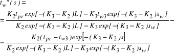
for a counterflow cooler:
in zone I:
![]()
(21)
![]()
(22)
in zone II:

(23)
(24)
while (Filek, et. al., 1999 a; Filek and Nowak, 1999)
![]()
(25)
![]()
(26)
![]()
(27)
![]()
(28)
![]()
(29)
![]()
(30)
(31)
Coefficients αw i αz were determined according to (Gutkowski, 1972; H*ussler, 1971; Kołodziejczyk and Rubik, 1969).
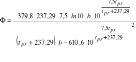
The temperature and humidity of the air leaving the cooler (t3 i x3) is determined from the set of equations below
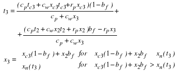
(32)
where: ![]()
, ![]()
.
Symbols in the above dependencies stand for:
b - absolute air pressure [Pa],
bf - coefficient of cooler shunting [-],
Fch - surface area of active lateral cooler section [m2],
Fw - internal area of heat exchanger [m2],
Fz - external area of heat exchanger [m2],
L - length of cooler [m],
M - stream of dry air mass [kg/s],
Mw - stream of cooling water mass [kg/s],
s - current co-ordinate [m],
sw - co-ordinate of boundary of zones of: dry cooling and wet cooling [m],
tpr - dew-point temperature of the cooled air [°C],
tw2 - temperature of cooling water in cooler section with co-ordinate s=0 (inlet of parallel-flow cooler, outlet of counter- flow cooler) [°C],
tw3 - temperature of cooling water in cooler section with co-ordinate s=L (outlet of parallel-flow cooler, inlet of counter-flow cooler) [°C],
twg - temperature of cooling water on the border of zones I and II in cooler [°C],
v - average velocity of air flow in cooler [m/s],
vw0 - calculated velocity of water flow in cooler [m/s],
Vcw - total capacity of heat exchanger tubes [m3],
xn - specific humidity of air saturated with water vapour [kg of H2O vapour/kg of dry air],
αw - heat absorption ratio on internal area of heat exchanger [W/(m2K)],
αz - heat absorption ratio on external area of heat exchanger [W/(m2K)],
ρ - air density converted to that of dry air [kg/m3],
ρw - water density [kg/m3].
COMPUTATIONAL EXAMPLE
As emphasised in the introduction, the example concerns parallel-flow and counter-flow GCCP-115 coolers, in co-ordination with with a WLE-1004A type fan. We have considered two states of air before cooling, which differ only in their specific humidity. The following figures have been assumed:
stream of cooling water mass
Mw = 3 kg/s,
inlet temperature of cooling water
tw2 = 12 °C (parallel-flow cooler),
tw3 = 12 °C (counter-current cooler),
temperature of air before fan
t1 = 29 °C,
specific humidity of air before fan
x1 = 11 g/kg or x1 = 16 g/kg,
absolute air pressure
b = 105 kPa.
By changing the rotational speed of the fan from 0,1 nn to nn (where nn stands for nominal speed), we examined the dependence of power Nc, Ncs, Ncw, Nu, Nus i Nuw and boundary coordinate sw on average velocity of air flowing through cooler v. It was assumed that the fan's characteristics for its nominal rotational speed can be described by means of polynomials in the following form:
Δpn(Qn) = a0+a1Qn+a2Qn2 (33)
ηwn(Qn) = a3+a4Qn+a5Qn2 (34)
where:
a0, a1, ..., a5 - known constants,
Qn - volumetric flow of air through cooler at nominal rotational speed of fan [m3/s],
Δpn - fan pressure at its nominal rotational speed [Pa],
ηwn - efficiency of fan at its nominal rotational speed [-]
For a known resistance of cooler R [Ns2/m8] we can write
RQn2 = a0+a1Qn+a2Qn2 (35)
By solving equation (35) we can determine Qn, and then from ηwn from equation (34).
For a rotational speed different from the nominal value n ≠ nn the following dependencies operate (Pawiński et. al., 1995)
![]()
(36)

(37)
In calculations a steady air density has been assumed, equal to its density before fan ρ, which may be calculated from the formula (Roszczynialski et. al., 1992)
![]()
(38)
whilst the coefficient of shunting of a GCCP-115 type cooler was dependant upon the air stream volume in accordance with the formula obtained from measurements (Nowak and Łukosz, 1999)
![]()
Q [m3/s] (39)
An increase in temperature of the air in the fan Δtwent was calculated from the formula (Information, 1984)
![]()
(40)
The knowledge of the thermodynamic parameters of the air which flows into the fan, and enters and leaves the cooler, made it possible to determine the previously mentioned powers and co-ordinate sw.
From calculations we obtained:
ρ = 1,190 kg/m3 for x1=11 g/kg,
ρ = 1,181 kg/m3 for x1=16 g/kg,
ηw = 0,57.
Other quantities, changing along with a change in the fan's rotational speed, are equal:
v from 3,19 m/s (for n=0,1 nn)
from 31,9 m/s (for n=nn).
Q from 1,37 m3/s to 13,7 m3/s,
bf from 0,022 to 0,197,
Δp from 20,1 Pa to 2010 Pa,
Δtwent from 0,03 °C to 2,95 °C for x1=11 g/kg,
from 0,03 °C to 2,97 °C for x1=16 g/kg.
The results of calculations of power and boundary co-ordinate sw, which at the same time is a width of dry cooling zone in the cooler, have been presented graphically in six diagrams.
When analysing those graphs, it can be stated that:
total power Nc of a counter-flow cooler is in the same conditions about 20-30% bigger than the power of a parallel-flow cooler; a similar conclusion may be reached with regard to the total power of the fan - cooler system Nu,
drying power Ncw=Nuw is clearly dependent on the specific humidity of the inducted air; the relative proportion of this part of the power in the total power (both Nc and Nu) decreases as the speed of air flowing through the cooler increases,
the power of air drying drops to zero when its velocity is sufficient; if the velocity exceeds this value, only dry cooling takes place in the whole cooler; then curves sw(v) - Fig. 5 and Fig. 6 reach a value of sw=L=300 cm,
air cooling powers (Ncs i Nus) depend on air velocity in a similar way as total powers Nc and Nu; the biggest differences occur when this velocity has small values, and decreases when the velocity goes up,
the power of the cooler alone Nc grows monotonically as velocity v goes up, while the power of system Nu reaches its maximum, then - because of an excessive increase in the temperature of the air in the fan - drops while the air velocity is still increasing; so there is a possibility to achieve a maximum thermal power of a given fan/air cooler system by changing the fan's rotational speed; from the point of view of energy, these are the most favourable working conditions for such a system,
the nature of curves sw(v) depends strongly on the directions of water and air flow through a cooler; in a parallel-flow cooler, in the conditions similar to boundary ones, between dry and wet cooling (sw whose value is close to L=300 cm) a slight change in the velocity of air flow considerably changes the width of zones I and II in the cooler, while in the same conditions in a counter-flow cooler the effect of v on sw is weaker; when the air velocity v drops in the width of zone I and II in both types of the cooler, for the same values x1, they tend to converge.
Figure 1. Power of a parallel-flow cooler in the function of mean velocity of air flow for:
a) x1 = 11 g/kg, b) x1 = 16 g/kg. Nc - total power,
Ncs - cooling power Ncw - drying power
Figure 2. Power of counter-flow cooler in the function of mean velocity of air flow for:
a) x1 = 11 g/kg, b) x1 = 16 g/kg. Nc - total power,
Ncs - cooling power, Ncw - drying power
Figure 3. The resultant power of the system of a parallel-flow cooler and fan in the function of mean velocity of air flow for:
a) x1 = 11 g/kg, b) x1 = 16 g/kg. Nu - total power,
Nus - cooling power, Nuw - drying power
Figure 4. The resultant power of the system of counter-flow cooler and fan in the function of mean velocity of air flow for:
a) x1 = 11 g/kg, b) x1 = 16 g/kg. Nu - total power,
Nus -cooling power, Nuw - drying power
Figure 5. The width of dry cooling zone in a parallel-flow cooler for:
a) x1 = 11 g/kg, b) x1 = 16 g/kg,
in the function of mean velocity of air flow
Figure 6. The width of dry cooling zone in a counter-flow cooler for:
a) x1 = 11 g/kg, b) x1 = 16 g/kg,
in the function of mean velocity of air flow
REFERENCES
Filek K., Holesz K., Nowak B., Roszkowski J., 1999, „Chłodzenie powietrza górniczą chłodnicą przeponową z kondensacją pary wodnej,” Archives of Mining Sciences, Vol. 44, No. 1, pp 3 - 21
Filek K., Nowak B., Roszkowski J., 1999, „Przybliżona metoda obliczania parametrów termodynamicznych czynnika chłodzonego i chłodzącego w przeciw-
prądowej chłodnicy powietrza,” Międzynarodowa Konferencja na temat „Najnowsze osiągnięcia
w zakresie przewietrzania kopalń oraz zwalczania zagrożeń pożarowych, gazowych i klimatycznych,” Szczyrk, pp 241 - 252
Filek K., Nowak B., 1999, Wymiana ciepła i masy
w górniczych przeponowych chłodnicach powietrza
o działaniu pośrednim. Biblioteka Szkoły Eksploatacji Podziemnej, Kraków
Gutkowski K., 1972, Chłodnictwo. Wybrane zagadnienia obliczeniowe, WNT, Warszawa
Häussler W., 1971, Zastosowanie wykresu i-x
w inżynierii sanitarnej, Arkady, Warszawa
Holesz K., 1997, „Temperatura i wilgotność powietrza w górniczych chłodnicach przeponowych w stanach nieustalonych,” Praca doktorska, Kraków
Informacja zespołu d/s klimatyzacji i przewietrzania głębokich kopalń, 1984, Główne Biuro Studiów
i Projektów Górniczych, No. 2
Kołodziejczyk L., Rubik M., 1969, Technika chłodnicza w klimatyzacji, Arkady, Warszawa
Nowak B., Łukosz M., 1999, „Wpływ natężenia przepływu powietrza przez górniczą przeciwprądową chłodnicę przeponową o działaniu pośrednim na jej współczynnik bocznikowania,” Kwartalnik AGH, No. 3, pp 187 - 194
Pawiński J., Roszkowski J., Strzemiński J., 1995, Przewietrzanie kopalń, Śląskie Wydawnictwo Techniczne, Katowice
Roszczynialski W., Trutwin W., Wacławik J., 1992, Kopalniane pomiary wentylacyjne. Wydawnictwo „Śląsk”, Katowice
2
I SZKOŁA AEROLOGII GÓRNICZEJ 1999
5
368
PROCEEDINGS OF THE 7TH INTERNATIONAL MINE VENTILATION CONGRESS
369
THE EFFECT OF THE VELOCITY OF AIR FLOWING THROUGH
Wyszukiwarka
Podobne podstrony:
3475
200403 3475
3475
3475
3475
3475
3475
3475(1)
3475
uchwala sp 3475
więcej podobnych podstron