2X

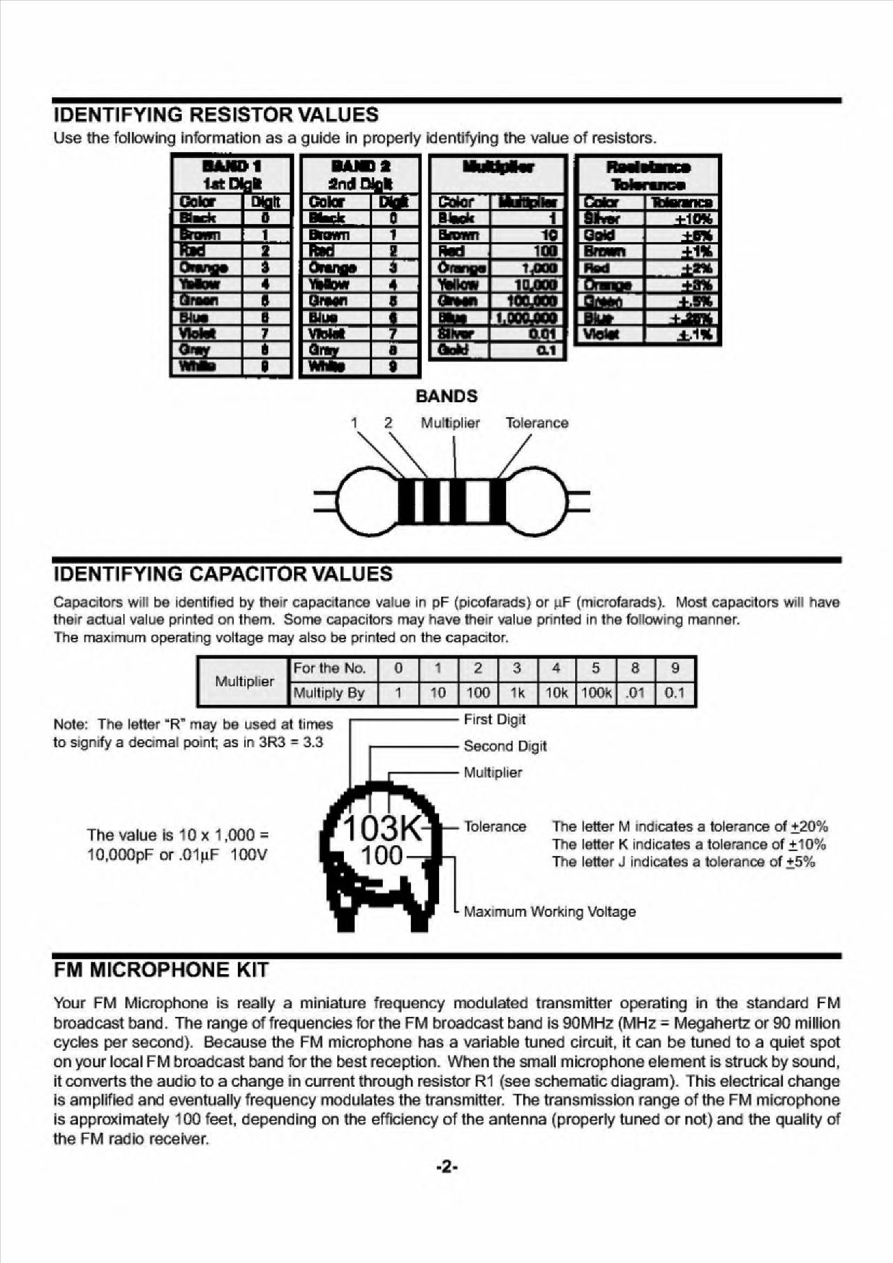
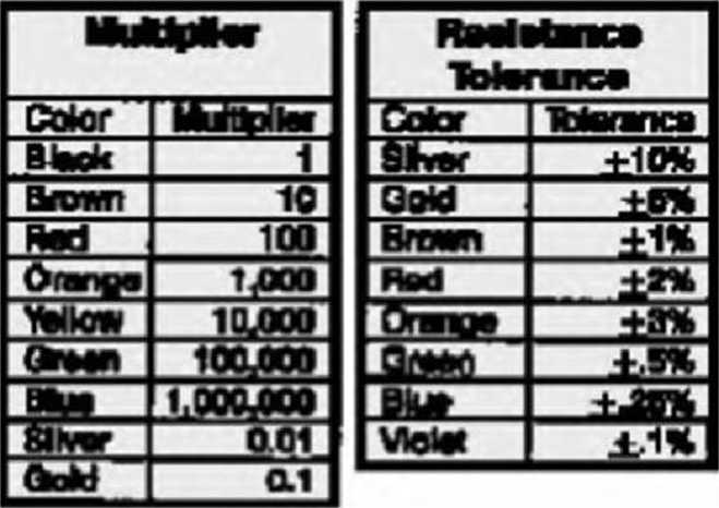
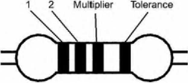
IDENTIFYING RESISTOR VALUES
Use the following information as a guide in properly identifying the value of resistors.
BAWI
utEfei

E
W _
Qr*flry


ł
_
E a
J
BANDS

IDENTIFYING CAPACITOR VALUES
Notę: The letter “R" may be used at times to signify a deamal point; as in 3R3 = 3.3
The value is 10 x 1,000 = 10,000pF or ,01pF 100V

Maximum Working Voltage
Tolerance The letter M indicates a tolerance of +20% The letter K indicates a tolerance of ±10% The letter J indicates a tolerance of +5%
Capaotors wili be identified by their capacitance value in pF (picofarads) or pF (microfarads). Most capaotors will have their actual value printed on them. Some capacitors may have their value pnnted in the following manner.
The maximum operating voltage may also be printed on the capacrtor.
|
Multiplier |
For the No. |
0 |
1 |
2 |
3 |
4 |
5 |
8 |
9 |
|
Multiply By |
1 |
10 |
100 |
1k |
10k |
100k |
.01 |
0.1 |
First Digit Second Digit Multiplier
FM MICROPHONE KIT
Your FM Microphone is really a miniaturę frequency modulated transmitter operating in the standard FM broadcast band. The rangę of frequencies for the FM broadcast band is 90MHz (MHz = Megahertz or 90 million cycles per second). Because the FM microphone has a variable tuned Circuit, it can be tuned to a quiet spot on your local FM broadcast band for the best reception. When the smali microphone element is struck by sound, it converts the audio to a change in current through resistor R1 (see schematic diagram). This electrical change is amplified and eventually frequency modulates the transmitter. The transmisslon rangę of the FM microphone is approximately 100 feet, depending on the efficiency of the antenna (properly tuned or not) and the quality of the FM radio receiver.
-2-
Wyszukiwarka
Podobne podstrony:
local side friction fs to the cone resistance qc, has to be expressed as a percentage in order
Workarounds for Reliability with Non-Transactional Tables But how do you use the features of MySQL S
88 Małgorzata KamienieckaTHE POSSIBILITIES TO USE THE TOOLS OF FINANCIAL ACCOUNTING IN LOGISTICS Sum
PZK277 277LITERATURA Russo, J. E. (1977). The value of unitę price information./nwm#/ ofMarketing Re
00219 a6d333666646e915e39fbc117115f5 221 Applications of the EWMA The Control Algorithm In this al
70. A.69057 ECONOMIST on Wall Street : notes on the sanctity of gold, the value of
Sample Lab Reportpago 1Boa Awesome Partners Marie Curie. AJbert Einstein January 1. 2020 Finding the
133 thousand zlotys per hectarc) and the value of fixcd assets (1385 zlotys per hcctarc). The va!uc
2. 2. 3. www.mtuexam.blogspot.in 10 W/m2.K. Calculate the value of highcst current that may bc passe
1972 Nations Unieś — Recueil des Traites 97 (ix) the tax on the value of vacant lots; (hereinaf
DSC06054 (2) 50 Stanisława Golinowska, Piotr Broda- Wysocki Gi łlies P. (1997), Sociał Capital: Reco
THE VALUE OF AN IDEA UCl •* łMt *JUHC O# IT
What is the value of a single "like" in Facebook7 ^ Oznacz zdjęcie 9 Dodaj lokalizację / E
THE PROBLEMS OF QUALIFYING THE VALUE OF REAL ESTATE WITH THE METHOD OF THE STATISTICAL ANALYSIS
autostretching0245 OTHER WRITINGS ABOUT THE VALUE OF STRETCHING The knowledge that some muscle group
18ddg08 NetWork Configuration Identification j Access Control ] Windows uses the following informati
więcej podobnych podstron