p03 (15)
1940-1952 C I V I L I A N KODELS WL&G
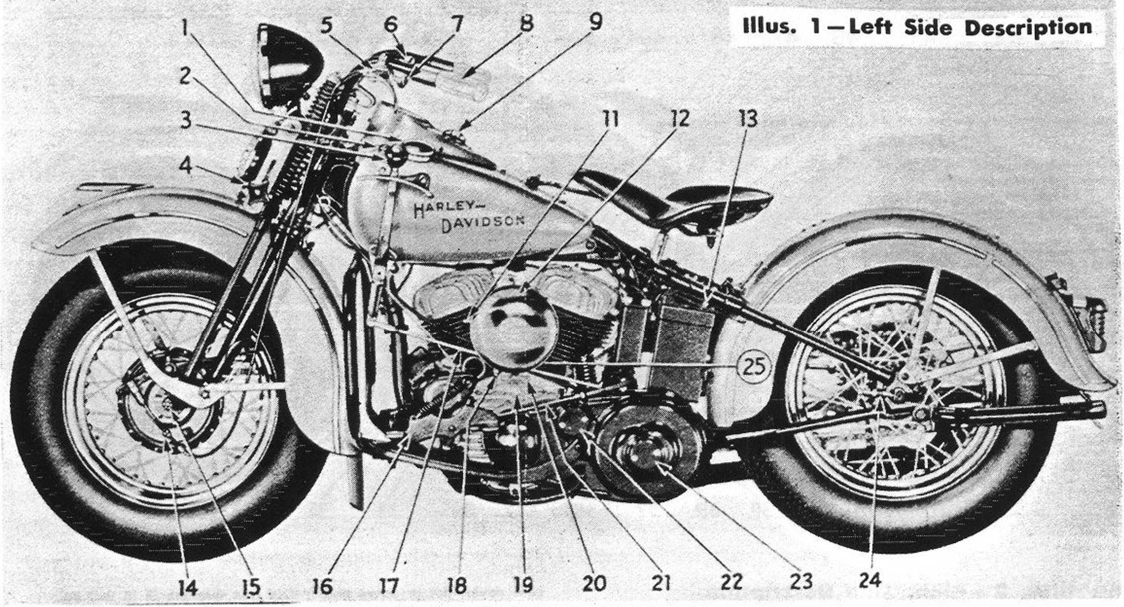
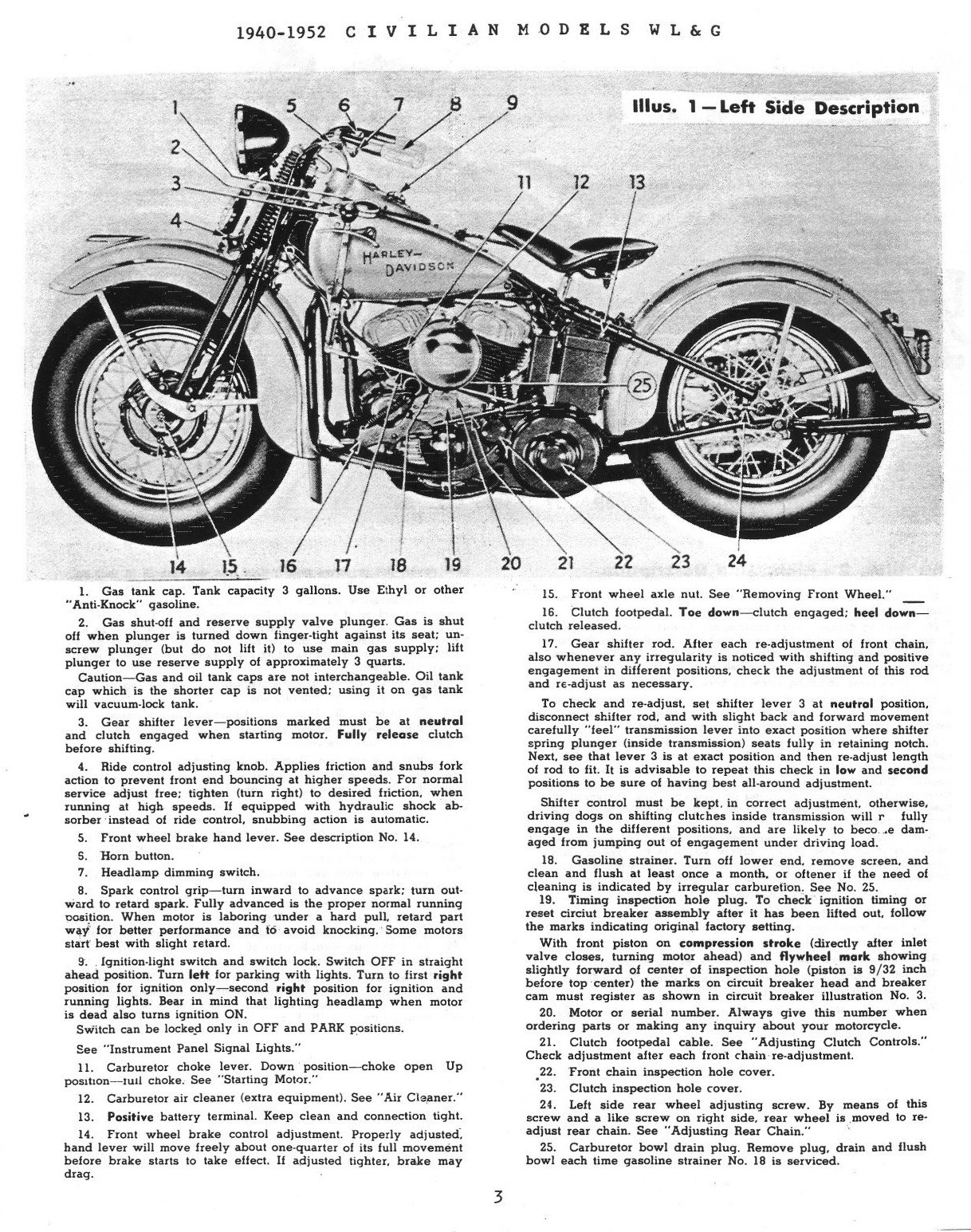
1. Gas tank cap. Tank capacity 3 gallons. Use Ethyl or other "Anti-Knock" gasoline.
2. Gas shut-off and reserve supply valve plunger. Gas is shut off when plunger is turned down finger-tight against its seat; un-screw plunger (but do not lift it) to use main gas supply; lift plunger to use reserve supply of approximately 3 ąuarts.
Caution—Gas and oil tank caps are not interchangeable. Oil tank cap which is the shorter cap is not vented; using it on gas tank will vacuum-lock tank.
3. Gear shifter lever—positions marked must be at neutral and clutch engaged when starting motor. Fully release clutch before shifting.
4. Ride control adjusting knob. Applies friction and snubs fork action to prevent front end bouncing at higher speeds. For normal service adjust free; tighten (tura right) to desired friction, when running at high speeds. If eąuipped with hydraulic shock absorber instead of ride control, snubbing action is automatic.
5. Front wheel brake hand lever. See description No. 14.
S. Horn button.
7. Headlamp dimming switch.
8. Spark control grip—tura inward to advance spark; tura out-ward to retard spark. Fully advanced is the proper normal running oosition. When motor is laboring under a hard puli, retard part way for better performance and to avoid knocking. Some motors start best with slight retard.
9. Ignition-light switch and switch lock. Switch OFF in straight ahead position. Tura lełt for parking with lights. Tura to first right position for ignition only—second right position for ignition and running lights. Bear in mind that lighting headlamp when motor is dead also turns ignition ON.
Switch can be locked only in OFF and PARK positions.
See “Instrument Panel Signal Lights.”
11. Carburetor choke lever. Down position—choke open Up position—tuli choke. See "Starting Motor."
12. Carburetor air cleaner (extra eąuipment). See "Air Cleaner."
13. Positive battery terminal. Keep clean and connection tight.
14. Front wheel brake control adjustment. Properly adjusted. hand lever will move freely about one-ąuarter of its fuli movement before brake starts to take effect. If adjusted tighter, brake may drag.
15. Front wheel axle nut. See "Removing Front Wheel." _
16. Clutch footpedal. Toe down—clutch engaged; heel down— clutch released.
17. Gear shifter rod. After each re-adjustment of front chain, also whenever any irregularity is noticed with shifting and positive engagement in different positions, check the adjustment of this rod and re-adjust as necessary.
To check and re-adjust. set shifter lever 3 at neutral position, disconnect shifter rod. and with slight back and forward movement carefully "feel" transmission lever into exact position where shifter spring plunger (inside transmission) seats fully in retaining notch. Next, see that lever 3 is at exact position and then re-adjust length of rod to fit. It is advisable to repeat this check in Iow and second positions to be surę of having best all-around adjustment.
Shifter control must be kept, in correct adjustment. otherwise, driving dogs on shifting clutches inside transmission will r fully engage in the different positions, and are likely to beco ,e dam-aged from jumping out of engagement under driving load.
18. Gasoline strainer. Tura off lower end. remove screen, and clean and flush at least once a month, or oftener if the need of cleaning is indicated by irregular carburetion. See No. 25.
19. Timing inspection hole pług. To check ignition timing or reset circiut breaker assembly after it has been lifted out, follow the marks indicating original factory setting.
With front piston on compression stroke (directly after inlet valve closes, turning motor ahead) and flywheel mork showing slightly forward of center of inspection hole (piston is 9/32 inch before top center) the marks on Circuit breaker head and breaker cam must register as shown in Circuit breaker illustration No. 3.
20. Motor or serial number. Always give this number when ordering parts or making any inąuiry about your motorcycle.
21. Clutch footpedal cable. See "Adjusting Clutch Controls." Check adjustment after each front chain re-adjustment.
22. Front chain inspection hole cover.
23. Clutch inspection hole cover.
24. Left side rear wheel adjusting screw. By means of this screw and a like screw on right side, rear wheel is moved to re-adjust rear chain. See "Adjusting Rear Chain."
25. Carburetor bowl drain pług. Remove pług, drain and flush bowl each time gasoline strainer No. 18 is serviced.
3
Wyszukiwarka
Podobne podstrony:
Le 15 novembre 1952, Tinstallation des machines chez les particuliers commence et une « Multivalue »
china20big Dragon / Drache Energy getaden / Erfolgreicłi 1904. 1916. 1928. 1940. 1952 1964 1976 1988
china20big Dragon / DracheEnergy geladen / Erfolgreicłi 1904, 1916, 1928. 1940, 1952 1964, 1976, 198
766. .The cetemony of the transfer of pwef. hcld at 4.45 p.m. on 15 Scpcember
BUREAU INTERNATIONAL POIDS & J1ESURES Le 15 avril 1952. Pavillon S£VRES (S.-i-O.) CERTIFICA.T du
Ciężar właściwy i stężenie ługu sodowego w temp. 15° % NaOH C. wf. % NaOH C. wł. % NaOH C.
— 7 — BULLETIN ECONOMIgUELA SITUATION DE L’ECONOMIE FRANęAISEAU 15 NOYEMBRE 1952 AU milłeu de ce der
Obraz % i ie faji o 15 9+ = ?^ VMtA ^ VM^ ES i f o*wl 15 IM w o, 250,^0 032 035 °5o A G63
fuel tank fuel type Fuel Tank Fuel tank capacity is 10.5 f (2.8 US gal) in-cluding 2.5 f (0.66 US ga
fuel tank fuel type Fuel Tank Fuel tank capacity is 10.5 ( (2.8 US gal) in-cluding 2.5 f (0.66 US ga
s&h 015 15 STRESGTfT AM) HEALTH random, not knowing what you are going to do or how you are going to
więcej podobnych podstron