2949775336
Comparison of Liąuid Propellant Rocket Engine Feed Systems - 1 - 3
I. INTRODUCTION
Since several decades the Systems to impel propellants inside the combustion chamber are based on the employment of turbo-pumps or a pressurized gas. However, in virtue of the technological advances of the last 10 years in matter of electric engines and batteries, is possible to think about the viability of development electric-pumps feed Systems.
One of the most difficult requirements to achieve when designing a rocket engine is to keep the weight as Iow as possible, because generally the payload is a smali fraction of the total weight. For this reason, this reąuirement tums out to be a basie parameter to compare the three Systems.
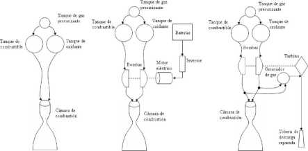
Beginning with a brief description of the parts that compose each feed system, the conceptual diagrams of each system are presented in figurę 1.

Figurę 1: Schemes of the 3 feed Systems to analyzing.
The figurę 1 shows that all the three systems have fuel and oxidizer tanks, and also a third tank containing a pressurized gas.
In the first system, that gas makes the work of displacing the propellants masses inside the combustion chamber. Hereby, the stored gas in the above mentioned tank is under high pressure with typical values ranging from 6.9MPa to 69MPa [1],
For the other two systems, the pumps make the work of displacing the propellants while the gas function is only to prevent cavitation in the pumps. Therefore, the gas mass necessary in such systems is much lower.
The two pumps systems differ from each other by the pump drive method. In the turbo-pump system, the device that provides power to the pumps is a gas turbinę (sometimes one by pump).
The available methods to drive the turbinę can be found detailed in [2], Here the gas generator method will be evaluated. Such a gas generator takes a fraction of the tank stored propellants and, by a separated combustion process (usually fuel rich), provides the gas that drives the turbinę. The gas generator is fed usually with propellants that are taken from the feed lines located after the pumps to improve the efficiency. This reąuires the use of some start method, being usual to use a solid fuel cartridge.
In the case here depicted, the turbinę gas discharge is done through a separated nozzle direct on the atmosphere (w'hich is named as open cycle turbopump system).
Otherwise, the electric pump system is driven by a brushless synchronous electric motor (also can have one by each pump). Each motor is fed by an inverter which converts the direct
Wyszukiwarka
Podobne podstrony:
Comparison of Liąuid Propellant Rocket Engine Feed Systems - 1 - 10 meepopllc 1 SLV (2.4.3) Replacin
Comparison of Liąuid Propellant Rocket Engine Feed Systems -1-9 At this point, is convenient to refe
Comparison of Liąuid Propellant Rocket Engine Feed Systems - 1 - 11 According to the previously expo
Comparison of Liąuid Propellant Rocket Engine Feed Systems - 1 - 12 Finally, combining the above exp
Comparison of Liąuid Propellant Rocket Engine Feed Systems - 1 - 15 The turbinę inlet gases are to a
Comparison of Liąuid Propellant Rocket Engine Feed Systems - 1 - 16 3.7. Materials It is necessary t
Comparison of Liąuid Propellant Rocket Engine Feed Systems - 1 - 1 REPORT N21COMPARISON OF LIOUID PR
Comparison of Liąuid Propellant Rocket Engine Feed Systems -1-2 CONTENTS I.
Comparison of Liąuid Propellcmt Rocket Engine Feed Systems - 1 - 5 where, my. Pressurizing gas mass
Comparison of Liąuid Propellant Rocket Engine Feed Systems - 1 - 6 0/F mf pfvf - -mp = mppa \+OIF) 1
Comparison of Liąnid Propellant Rocket Engine Feed Systems - 1 - 8 2.2.2. Propellant tank mass In a
Comparison ofLiąuid Propellant Rocket Engine Feed Systems -1-7 (N II £ (2.2.2) where, Ap: Sphere
Comparison ofLiąuid Pr opel fant Rocket Engine Feed Systems - 1 - 13 . gg-RTin (2.9.4) where, Rgg: T
Comparison ofLiguid Pr opel font Rocket Engine Feed Systems - 1 - 14 For each calculation routine, i
Comparison ofLiąuid PropeUant Rocket Engine Feed Systems - 1 - 17 Figurę 2: Synchronous motor specif
Comparison ofLiąuid Pr opel lani Rocket Engine Feed Systems - 1 - 18 Table 6: Proposed batteries t
Research Report.ELECTRIC FEED SYSTEMS FOR LIQUID PROPELLANT ROCKET ENGINES.Pablo Rachov, Hernan
RESEARCH REPORTSELECTRIC FEED SYSTEMS FOR LIOUID PROPELLANT ROCKET ENGINESPablo RACHOV LABORATO
więcej podobnych podstron