2949775331
Comparison ofLiąuid PropeUant Rocket Engine Feed Systems - 1 - 17
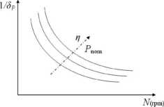
Figurę 2: Synchronous motor specific mass in function of their rotational speed. In dotted linę, the dependency with the efficiency and the nominał power is denoted.
Therefore, for the expected pumps operation speed rangę (from 10,000 rpm to 40,000 rpm) a 3.8 kW/kg power density is considered feasible within the power rangę reąuired (5 to 60 kW).
Hence, the following values for such parameters are adopted:
S„ ™kW kg k= 0-8
The inverter is characterized with the same motor parameters. In addition to the above mentioned denominations, these devices are often called Electronic Speed Controls (ESC) because they perform this function in scalę radio-controlled vehicles.
Next, a table with some examples of these devices is presented:
kg
0.85
|
Table 5: DC-Brushless Motors Inverters. | |||
|
Model |
Power Density | kW/kg | |
Efficiency |
Reference |
|
Jeti Advance 70 Pro |
41 |
- |
mi |
|
Jeti Advance 90 Pro |
37 |
- |
[13] |
|
Phocnix ICE HV 80 |
70.5 |
85% |
[171 |
|
Phoenix ICE HV 160 |
61.8 |
85% |
_LlH |
Finally, the power density and efficiency values adopted are:
Regarding batteries, there are various manufacturing tecnologies that should be considered. There are two parameters that relate both their efficiency and their mass. In one hand, is the power density while in the other hand is the energy density. The last one becomes very important as the operation time increases. It becomes a limiting factor for long operation times. Therefore, a technology offering both higher power and energy densities should be chosen, being one a morę important factor than the other according to the total engine buming time.
Among the most promising technologies there are:
• Lithium-Ion (Li-Ion)
• Lithium-Ion Polymer (Li-Po)
• Lithium-Sulfur (Li-S)
In the following table some typical data of these technologies are presented:
Wyszukiwarka
Podobne podstrony:
Comparison ofLiąuid Propellant Rocket Engine Feed Systems -1-7 (N II £ (2.2.2) where, Ap: Sphere
Comparison ofLiąuid Pr opel fant Rocket Engine Feed Systems - 1 - 13 . gg-RTin (2.9.4) where, Rgg: T
Comparison ofLiąuid Pr opel lani Rocket Engine Feed Systems - 1 - 18 Table 6: Proposed batteries t
Comparison of Liąnid Propellant Rocket Engine Feed Systems - 1 - 8 2.2.2. Propellant tank mass In a
Comparison of Liąuid Propellant Rocket Engine Feed Systems -1-9 At this point, is convenient to refe
Comparison of Liąuid Propellant Rocket Engine Feed Systems - 1 - 10 meepopllc 1 SLV (2.4.3) Replacin
Comparison of Liąuid Propellant Rocket Engine Feed Systems - 1 - 11 According to the previously expo
Comparison of Liąuid Propellant Rocket Engine Feed Systems - 1 - 12 Finally, combining the above exp
Comparison ofLiguid Pr opel font Rocket Engine Feed Systems - 1 - 14 For each calculation routine, i
Comparison of Liąuid Propellant Rocket Engine Feed Systems - 1 - 15 The turbinę inlet gases are to a
Comparison of Liąuid Propellant Rocket Engine Feed Systems - 1 - 16 3.7. Materials It is necessary t
Comparison of Liąuid Propellant Rocket Engine Feed Systems - 1 - 1 REPORT N21COMPARISON OF LIOUID PR
Comparison of Liąuid Propellant Rocket Engine Feed Systems -1-2 CONTENTS I.
Comparison of Liąuid Propellant Rocket Engine Feed Systems - 1 - 3 I. INTRODUCTION Since several dec
Comparison of Liąuid Propellant Rocket Engine Feed Systems - 1 - 4 current from the battery to altem
Comparison of Liąuid Propellcmt Rocket Engine Feed Systems - 1 - 5 where, my. Pressurizing gas mass
Comparison of Liąuid Propellant Rocket Engine Feed Systems - 1 - 6 0/F mf pfvf - -mp = mppa \+OIF) 1
Изображение37 5-16 Chapter 5 Engine electrical systems 18.4 Typical starter motor mounting for 2.5L
więcej podobnych podstron