
1
INTRODUCTION
GENERAL
This section contains a MAINTENANCE SCHEDULE
and the instructions for maintenance and inspection.
The MAINTENANCE SCHEDULE has time intervals
for inspection, lubrication and maintenance for your lift
truck. The service intervals are given in both operating
hours recorded on the lift truck hour meter, and in calen-
dar time. The recommendation is to use the interval that
comes first.
The recommendation for the time intervals are for eight
hours of operation per day. The time intervals must be
decreased from the recommendations in the MAINTE-
NANCE SCHEDULE for the following conditions:
a. If the lift truck is used more than eight hours per
day.
b. If the lift truck must work in dirty operating con-
ditions.
Your dealer for Hyster lift trucks has the equipment and
trained service personnel to do a complete program of
inspection, lubrication, and maintenance. A regular pro-
gram of inspection, lubrication, and maintenance will
help your lift truck give more efficient performance and
operate for a longer period of time.
Some users have service personnel and equipment to do
the inspection, lubrication, and maintenance shown in
the MAINTENANCE SCHEDULE. Service Manuals
are available from your dealer for Hyster lift trucks to
help users who do their own maintenance.
WARNING
Do not make repairs or adjustments unless you have
both authorization and training. Repairs and ad-
justments that are not correct can make a dangerous
operating condition.
WARNING
Do not operate a lift truck that needs repairs. Report
the need for repairs immediately. If repair is neces-
sary, put a “DO NOT OPERATE” tag in the opera-
tor’s area. Remove the key from the key switch.
HOW TO MOVE A DISABLED LIFT TRUCK
WARNING
Use extra caution when towing a lift truck if any of
the following conditions exist:
a. Brakes do not operate correctly.
b. Steering does not operate correctly.
c. Tires are damaged.
d. Traction conditions are bad.
e. The lift truck must be towed on a slope.
If the engine cannot run, there is no power available
for the hydraulic steering system and the service
brakes. This condition can make the lift truck diffi-
cult to steer and stop. If the lift truck uses power
from the engine to help apply the brakes, the applica-
tion of the brakes will be more difficult. Poor trac-
tion can cause the disabled lift truck or towing vehi-
cle to slide. A slope will also make the lift truck more
difficult to stop.
Never lift and move a disabled lift truck unless the
disabled lift truck MUST be moved and cannot be
towed. A lift truck used to move a disabled lift truck
MUST have a capacity rating equal to or greater
than the weight of the disabled lift truck. The capac-
ity of the lift truck used to move a disabled lift truck
must have a load center equal to half the width of the
disabled lift truck. See the nameplate of the disabled
lift truck for the approximate total weight. The forks
must extend the full width of the disabled lift truck.
Put the weight center of the disabled lift truck on
load center of the forks. Be careful to not damage the
under side of the lift truck.
How to Tow a Lift Truck
1. The towed lift truck must have an operator.
2. Raise the carriage and forks approximately 30 cm (12
inches) from the surface. Install a chain to prevent the
carriage and mast channels from moving.
3. Tow with another lift truck of equal or larger capacity
than the disabled lift truck. Install a load of approxi-
mately half–capacity on the forks of the lift truck that is
being used to tow the disabled lift truck. The half–ca-
2
pacity load will increase the traction of the lift truck.
Keep the load as low as possible.
4. Use a towing link made of steel that fastens to the tow
pins in the counterweights of both lift trucks.
5. Release the parking brake.
6. Tow the lift truck slowly.
HOW TO PUT A LIFT TRUCK ON BLOCKS
WARNING
The lift truck must be put on blocks for some types of
maintenance and repair. The removal of the follow-
ing assemblies will cause large changes in the center
of gravity: mast, drive axle, battery or counter-
weight. When the lift truck is put on blocks, put addi-
tional blocks in the following positions to maintain
stability:
a. Before removing the mast and drive axle, put
blocks under the counterweight so that the lift
truck can not fall backward.
b. Before removing the counterweight, put
blocks under the mast assembly so that the lift
truck can not fall forward.
The surface must be solid, even, and level when the
lift truck is put on blocks. Make sure that any blocks
used to support the lift truck are solid, one piece
units.
NOTE: Some lift trucks have lifting eyes. These lift
points can be used to raise the lift truck so that blocks can
be installed.
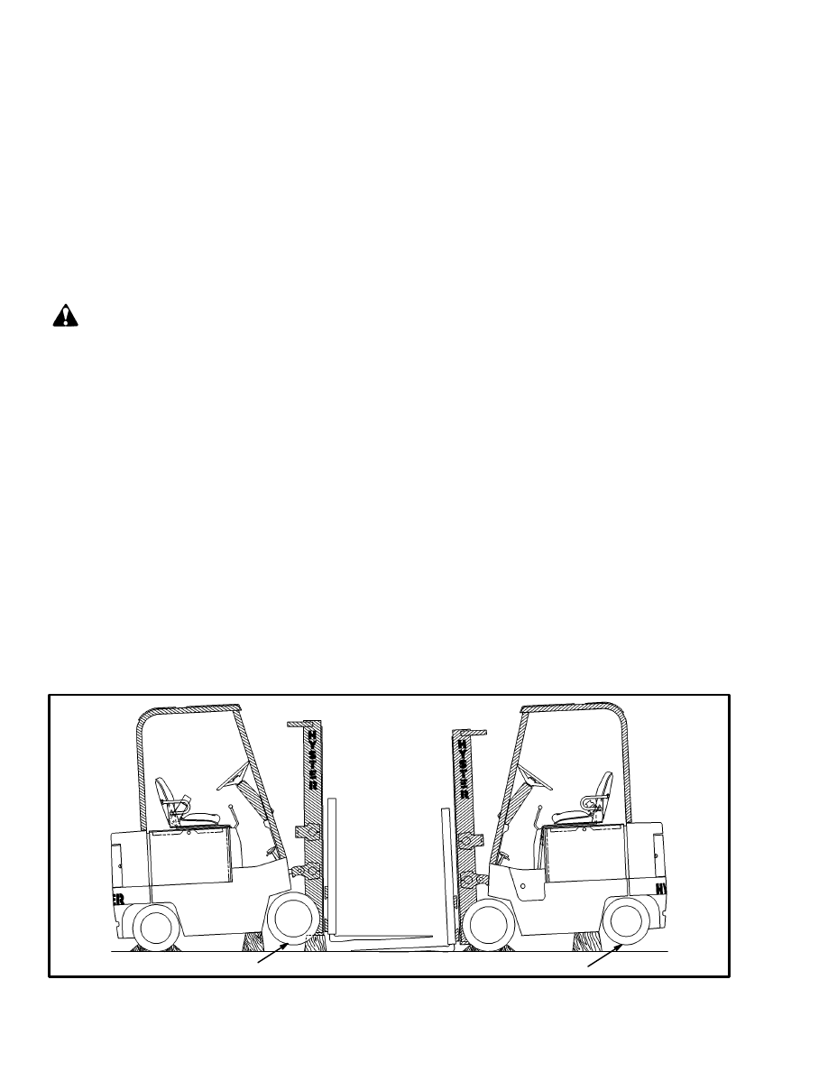
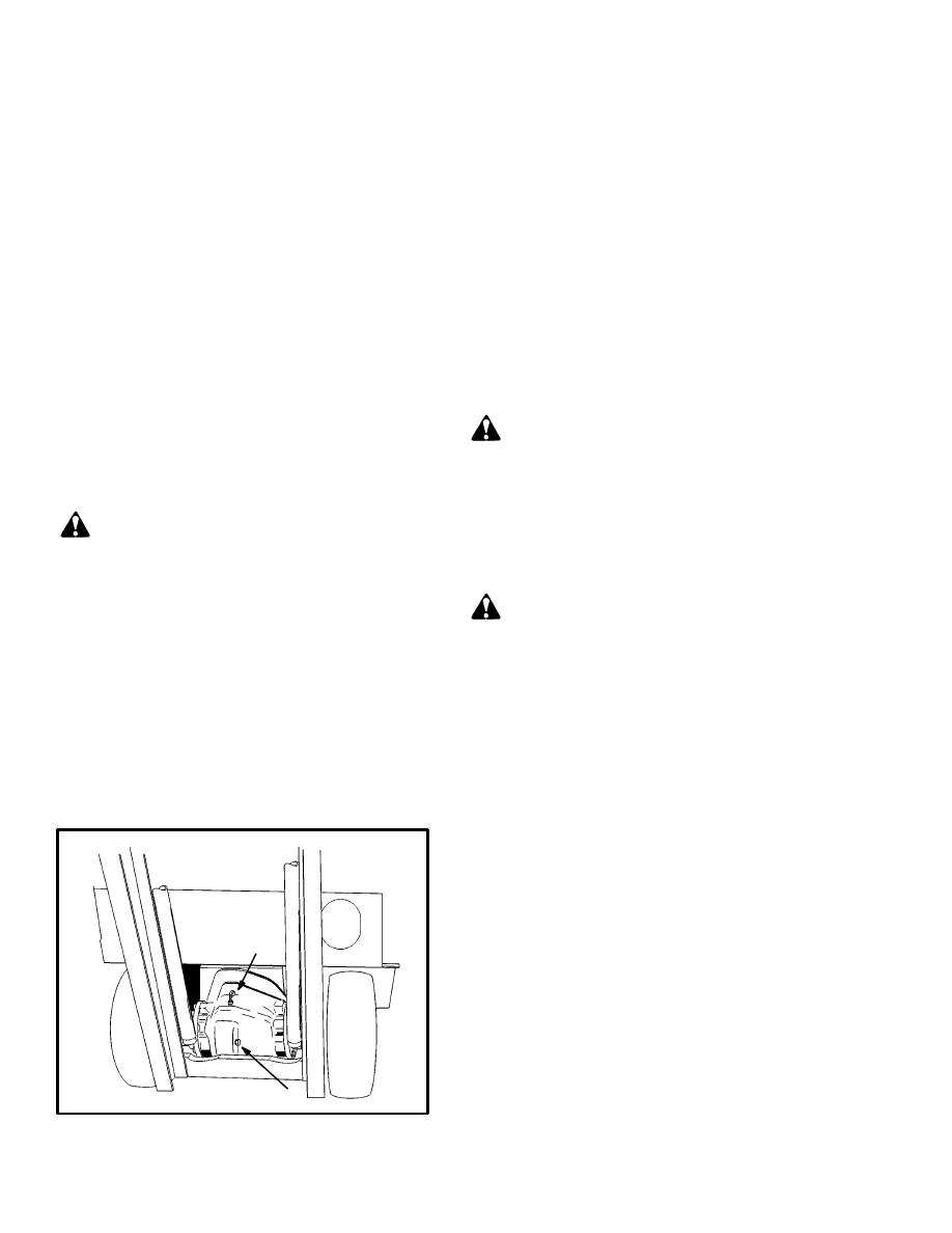
How To Raise the Drive Tires (See FIGURE 1.)
1. Put blocks on each side (front and back) of the steer-
ing tires to prevent movement of the lift truck.
2. Put the mast in a vertical position. Put a block under
each outer mast channel.
3. Tilt the mast fully forward until the drive tires are
raised from the surface.
4. Put additional blocks under the frame behind the drive
tires.
5. If the hydraulic system will not operate, use a hydrau-
lic jack under the side of the frame near the front. Make
sure that the jack has a capacity equal to at least half the
weight of the lift truck. See the nameplate.
How To Raise the Steering Tires
(See FIGURE 1.)
1. Apply the parking brake. Put blocks on both sides
(front and back) of the drive tires to prevent movement
of the lift truck.
2. Use a hydraulic jack to raise the steering tires. Make
sure that the jack has a capacity of at least 2/3 of the total
weight of the lift truck as shown on the nameplate.
3. Put the jack under the steering axle or frame to raise
the lift truck. Put blocks under the frame to support the
lift truck.
DRIVE TIRES
STEERING TIRES
11473
FIGURE 1. PUT THE LIFT TRUCK ON BLOCKS
3
11576
21
8
6
9
24
17
20
4
3
18
7
1
14
16
8
23
22
19
3
15
2
13
12
9
10
11
5
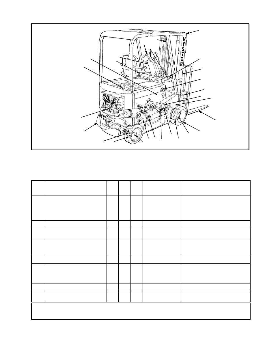
FIGURE 2. MAINTENANCE POINTS
MAINTENANCE SCHEDULE
ITEM
NO.
ITEM
8 hr/
Dai-
ly
350
hr/
2 mo
2000
hr/
1 yr
PROCEDURE
OR QUANTITY
SPECIFICATION
1
HYDRAULIC OIL (Total)
E/J1.25–1.75XL (E25–35XL)
E2.00–3.00XL (E40–60XL)
E3.50–5.50XL (E70–120XL)
j2.00–3.00XL (J40–60XL)
X
C
17 litre (18 qt)
19 litre (20 qt)
19 litre (20 qt)
37 litre (39 qt)
API SC/CC
–18
°
C to 38
°
C (0
°
F to 100
°
F)
SAE 10W
CHECK FOR OIL LEAKS
X
Check for Leaks
2
BATTERY
BATTERY RESTRAINT
X
1
Check Condition
3
TIRES
AIR PRESSURE
(Pneumatic Tires)
X
X
Check Condition
Check Air Pressure
See Nameplate
4
FORKS
X
Check Condition
5
LIFT CHAINS
X
L*
X
Check Condition
and Lubrication
Check Adjustment
and Length
Engine Oil
6
MAST AND CARRIAGE
X
Check Operation
7
SERVICE BRAKES
X
X
Check Operation
Check Condition
X=Check
C=Change
L=Lubricate
1
Equalization Charge is required approximately each month
* Lubricate every 250 hours of operation.
NOTE: Never use steam to clean electrical parts. See the
Service Manual for cleaning information.

4
MAINTENANCE SCHEDULE
ITEM
NO.
ITEM
8 hr/
Dai-
ly
350
hr/
2 mo
2000
hr/
1 yr
PROCEDURE
OR QUANTITY
SPECIFICATION
SAFETY LABELS
X
Replace as
Necessary
See Parts Manual
8
PARKING BRAKE
X
Check Operation
9
DIRECTION/SPEED CONTROLS
X
Check Operation
10
STEERING CONTROLS
STEERING COLUMN LATCH
X
X
Check Operation
Check Operation
11
HORN, GAUGES, LIGHTS,
ALARMS
X
Check Operation
12
SEAT BELT, HIP RESTRAINTS
AND SEAT RAILS
X
Check Condition
13
BRAKE FLUID
X
0.25 litre (0.5 pint)
SAE J–1703
14
HYDRAULIC TANK BREATHER
X
Clean or Replace
SEAT (PARKING) BRAKE
ADJUSTMENT
X
Service Person to
make Adjustments
15
CONTACTORS
X
C
2
Check Condition
16
MOTOR BRUSHES
X
3
Check Condition
17
DIFFERENTIAL AND SPEED
REDUCER
X
C
3.3 litre (3.5 qt)
5.2 litre (5.5 qt)
(E70–120XL)
Ultra Gear Lube Gear Oil
SAE 80W (Chevron Oil Co.)
or SAE 90W EP
18
WHEEL NUT TORQUE
E25–35XL (Drive Wheel)
E40–60XL (Drive Wheel)
E70–120XL (Drive Wheel)
J40–60XL (Drive Wheel)
J40–60XL (Steer Wheel)
X
Check Torque
155 N.m (115 lbf ft)
237–305 N.m (175–225 lbf ft)
600 N.m (443 lbf ft)
237–305 N.m (175–225 lbf ft)
155 N.m (115 lbf ft)
19
TIE RODS, STEERING
(E25–35XL) (J40–60XL)
L*
4 Fittings
Multi–Purpose Grease with 2–4%
Molybdenum Disulphide
20
21
MAST PIVOTS
MAST SLIDING SURFACES
L
L
2 Fittings
As Required
Multi–Purpose Grease with 2–4%
Molybdenum Disulphide
22
SPINDLE BEARINGS
(J40–60XL)
L*
As Required
Multi–Purpose Grease with 2–4%
Molybdenum Disulphide
1
HYDRAULIC FILTER
C
4
1
See Parts Manual
23
WHEEL BEARINGS
L
As Necessary
Multi–Purpose Grease with 2–4%
Molybdenum Disulphide
24
FORK GUIDES AND LOCKS
X
L
As Necessary
Engine Oil
X=Check
C=Change
L=Lubricate
3
Check after 500 hours. If brush wear is slow, extend the interval
to check to 1000 hours of opewration.
NOTE: Never use steam to clean electrical parts.
See the Service Manual for cleaning information.
2
Replace the contacts for the hydraulic pump contactor every
1000 hous of operation. Replace other contacts when thickness
is reduced to 30% of new contacts.
* Lubricate every 250 hours of operation.
4
Change filters on NEW lift trucks at first 100 hours on hourmeter.
5
MAINTENANCE PROCEDURES
EVERY 8 HOURS OR DAILY
HOW TO MAKE CHECKS WITH KEY
SWITCH OFF
Inspect the lift truck every eight hours or daily before
use. Put the lift truck on a level surface. Lower the car-
riage and forks and turn the key switch to OFF. Apply
the parking brake. Open the access panels and inspect
for leaks and conditions that are not normal. Clean any
oil spills. Make sure that lint, dust, paper and other mate-
rials are removed from the compartments.
Hydraulic System (See FIGURE 3.)
WARNING
The hydraulic oil is HOT at operating temperature.
Do not permit the hot oil to contact the skin and
cause a burn.
Hydraulic oil under pressure can be injected into the
skin. Never check for leaks by putting hands on a hy-
draulic line under pressure.
CAUTION
Do not permit dirt to enter the hydraulic system
when the oil level is checked or the filter is changed.
Never operate the pump without oil in the hydraulic
system. The operation of the hydraulic pump
without oil will damage the pump.
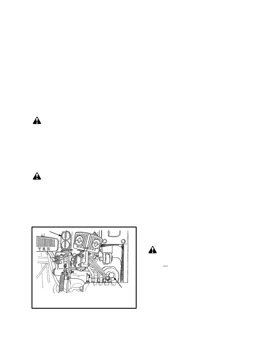
FIGURE 3. HYDRAULIC AND BRAKE
CHECKS
1. HYDRAULIC TANK
2. BRAKE FLUID RESERVOIR
11450
2
1
Check the hydraulic oil level when the oil is at operating
temperature, the carriage is lowered and the key switch
is in the OFF position. Add hydraulic oil only as
needed. If more hydraulic oil is added than the “FULL”
level, hydraulic oil will leak from the breather during
operation.
Inspect the hydraulic system for leaks and damaged or
loose components.
Battery
Make sure that the voltage and the weight of the battery
are correct as shown on the nameplate. See the OPER-
ATING MANUAL to check for correct battery dimen-
sions.
Keep the battery case, top cover and the area for the bat-
tery clean and painted. Leakage and corrosion from the
battery can cause a malfunction in the electric controls
of the lift truck. Use a water and sodium bicarbonate so-
lution (soda) to clean the battery and the battery area.
Keep the top of the battery clean, dry and free of corro-
sion.
Make sure the battery is charged and has the correct
voltage and ampere hour rating for the lift truck (see the
nameplate).
Inspect the battery case, connector and cables for dam-
age, cracks or breaks. See the battery dealer in the area to
repair any damage. Check the level of the electrolyte
daily on a minimum of one cell. The correct level is
half–way between the top of the plates and the bottom of
the fill hole. Add only distilled water.
WARNING
If the lift truck was operated with a low battery,
inspect all contactors for welded contacts BEFORE
you connect a charged battery. The lift truck can not
be controlled if contacts are welded. This condition
can cause personal injury when the battery is
connected.
Do not put tools on the battery.
The acid in the electrolyte can cause injury. If the
electrolyte is spilled, use water to flush the area.
Make the acid neutral with a solution of sodium
6
bicarbonate (soda). Acid in the eyes must be flushed
with water immediately.
Batteries generate explosive fumes. Keep the vents in
the caps clean. Keep sparks or open flames away
from the battery area. Do not make a spark from the
battery connections. Disconnect the battery when
doing maintenance.
Battery Restraint System (See FIGURE 4.)
WARNING
The battery must fit the battery compartment so that
the battery restraint will operate correctly. A loose
battery can cause serious injury and property
damage if the lift truck overturns. Use spacers to
prevent the battery from moving more than 13 mm
(0.5 in) in any horizontal direction.
The battery restraint system is a heavy steel seat plate
that has a hinge at the front of the battery compartment.
Spacers are used inside the battery compartment to pre-
vent horizontal movement of the battery. An additional
battery retention bar is used on all models
E3.50–5.50XL (E70–120XL) where batteries can be
longer. This bar has a hinge fastened to the counter-
weight and is part of the hood mechanism on lift truck
with hoods. The bar is also installed on lift trucks with-
out hoods.
WARNING
The battery restraint and its latch mechanisms must
operate correctly before a lift truck is operated. A
loose battery can cause serious injury and property
damage if the lift truck overturns. On E3.50–5.50XL
(E70–120XL) units the battery retention bar must be
down and under the seat and battery restraint plate.
Make sure the battery has a cover if the lift truck
does not have a hood.
To operate correctly, the battery restraint plate must be
locked in the down position. On E3.50–5.50XL
(E70–120XL) units the battery retention bar (and hood)
must be lowered first, then the battery restraint plate is
locked in the down position over the bar. Use spacers to
prevent horizontal movement of the battery. Use the
knob near the hinge to release the battery restraint plate
(see FIGURE 4.). Use the handle on the restraint plate to
raise the plate and seat. A spring brace will hold the as-
sembly in the up position. Raise the hood if a hood is in-
stalled. Make sure that the battery cannot move more
than a total of 13 mm (0.5 in) in any one horizontal direc-
tion. Make sure the correct spacers are installed to pre-
vent the movement.
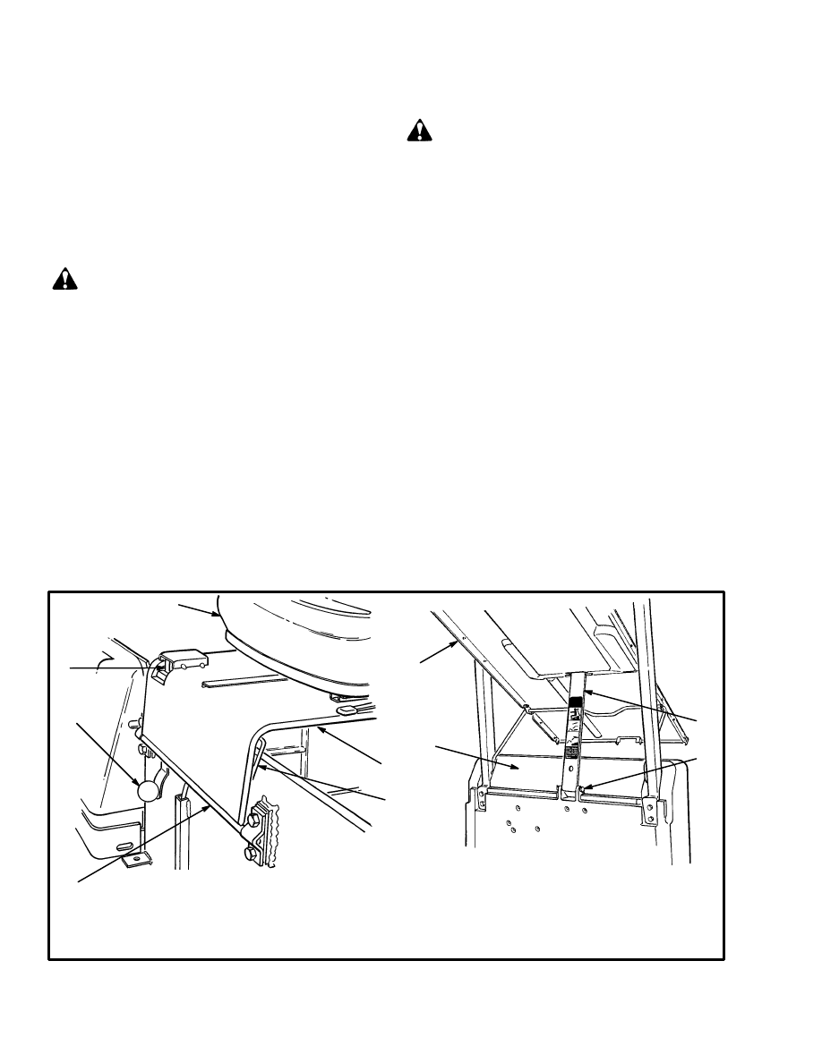
11512
1. SEAT
2. BATTERY RESTRAINT (SEAT PLATE)
3. KNOB FOR LATCH MECHANISM
4. HINGE
5. LATCH
6. SPRING BRACE
7. HOOD
8 BATTERY RETENTION BAR
(E70–120XL ONLY)
9. COUNTERWEIGHT
2
1
3
4
5
6
4
8
7
9
11512
FIGURE 4. BATTERY RESTRAINT
7
If necessary, adjust the battery spacer system as de-
scribed in HOW TO CHANGE THE BATTERY under
GENERAL PROCEDURES. See your dealer for Hys-
ter lift trucks to replace damaged or missing spacers.
Push the seat and the battery restraint down until the
latch locks. Make sure the battery restraint is locked se-
curely. Lift on the battery restraint to make sure it is
latched and will not move.
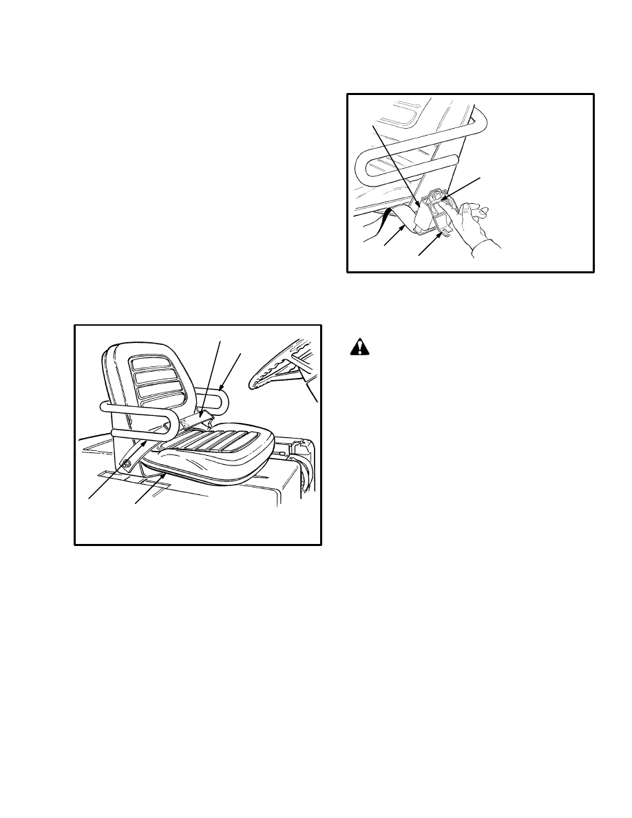
Operator Restraint System
(See FIGURE 5. and FIGURE 6.)
The seat belt, hip restraint brackets, seat and seat rails,
battery restraint (seat plate) and latch are all part of the
operator restraint system. Each item must be checked to
make sure it is attached securely, functions correctly and
is in good condition.
1. HIP RESTRAINTS
2. SEAT BELT
3. SEAT RAILS
11848
2
1
1
3
FIGURE 5. OPERATOR RESTRAINT SYSTEM
The end of the seat belt must fasten correctly in the latch.
Make sure the seat belt pulls from the retractor assembly
and retracts smoothly. The seat belt must be in good con-
dition. A seat belt that is damaged or worn will not give
protection when it is needed. If the seat belt can not be
pulled from the retractor assembly, remove the screw
that keeps the cover on the retractor. Push the bar to re-
lease the spool. Straighten the belt so that it will pull and
retract smoothly from the retractor assembly. (See
FIGURE 6.)
Make sure that the seat is not loose on the rails. The seat
must lock tightly in position, but move freely when un-
locked. The seat rails must be correctly fastened to the
mount surface.
1. COVER, OPEN
2. BELT
RETRACTOR
3. SEAT BELT
4. BAR
11806
2
1
3
4
FIGURE 6. RELEASE A JAMMED SEAT BELT
Inspection Of The Mast, Forks And Lift
Chains (See FIGURE 7. and FIGURE 8.)
WARNING
Lower the lift mechanism completely. Never allow
any person under a raised carriage. Do not put any
part of your body in or through the lift mechanism
unless all parts of the mast are completely lowered,
the key switch is in the OFF position and the key is
removed.
Do not try to correct the alignment of the fork tips by
bending the forks or adding shims. Replace
damaged forks.
Never repair damaged forks by heating or welding.
Forks are made of special steel using special
procedures. Replace damaged forks.
1. Inspect the welds on the mast and carriage for cracks.
Make sure that the capscrews and nuts are tight.
2. Inspect the channels for wear in the areas where the
rollers travel. Inspect the rollers for wear or damage.
3. Inspect the load backrest extension for cracks and
damage.
4. Inspect the forks for cracks and wear. Check that the
fork tips are aligned within 13 mm (0.5 in) of each other.
See FIGURE 7. Check that the bottom of the fork is not
worn (Item 4).
5. Replace any damaged or broken parts that are used to
keep the forks locked in position.
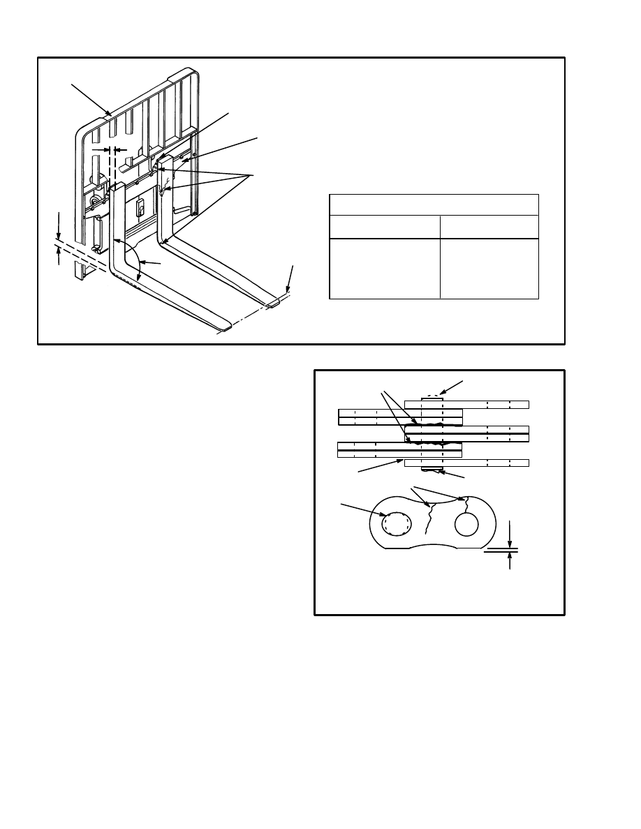
8
1. TIP ALIGNMENT (MUST BE WITHIN
3% OF FORK LENGTH
2. CRACKS
3. LATCH DAMAGE
4. HEEL OF FORK (MUST BE 90% OF
DIMENSION “X”)
5. CARRIAGE
6. LOAD BACKREST EXTENSION
7. MAXIMUM ANGLE 93
°
FORK TIP ALIGNMENT
LENGTH OF FORKS
3% DIMENSION
915 mm (36 in)
27 mm (1.10 in)
1220 mm (48 in)
37 mm (1.45 in)
1830 mm (72 in)
55 mm (2.15 in)
10221
X
1
3
4
5
6
2
7
FIGURE 7. CHECK THE FORKS
6. If the lift truck is equipped with a side–shift carriage
or attachment, inspect the parts for cracks and wear.
Make sure the parts that fasten the side–shift carriage or
attachment to the carriage are in good condition.
7. Inspect the lift chains for cracks and broken links and
pins. See FIGURE 8.
8. Make sure that the lift chains are correctly lubricated.
Use 30W engine oil or Hyster Chain and Cable Lubri-
cant (Hyster Part No. 171350).
9. Inspect the chain anchors and pins for cracks and
damage.
10. Make sure the lift chains are adjusted so that they
have equal tension. Adjustment or replacement of the
lift chains must be done by authorized personnel. See
LIFT CHAIN ADJUSTMENTS in GENERAL PRO-
CEDURES in this section.
6705
1
2
3
4
5
6
7
1. WORN PIN
2. CRACKS
3. EDGE WEAR
4. HOLE WEAR
5. LOOSE LEAVES
6. DAMAGED PIN
7. CORROSION
FIGURE 8. CHECK THE LIFT CHAINS
9
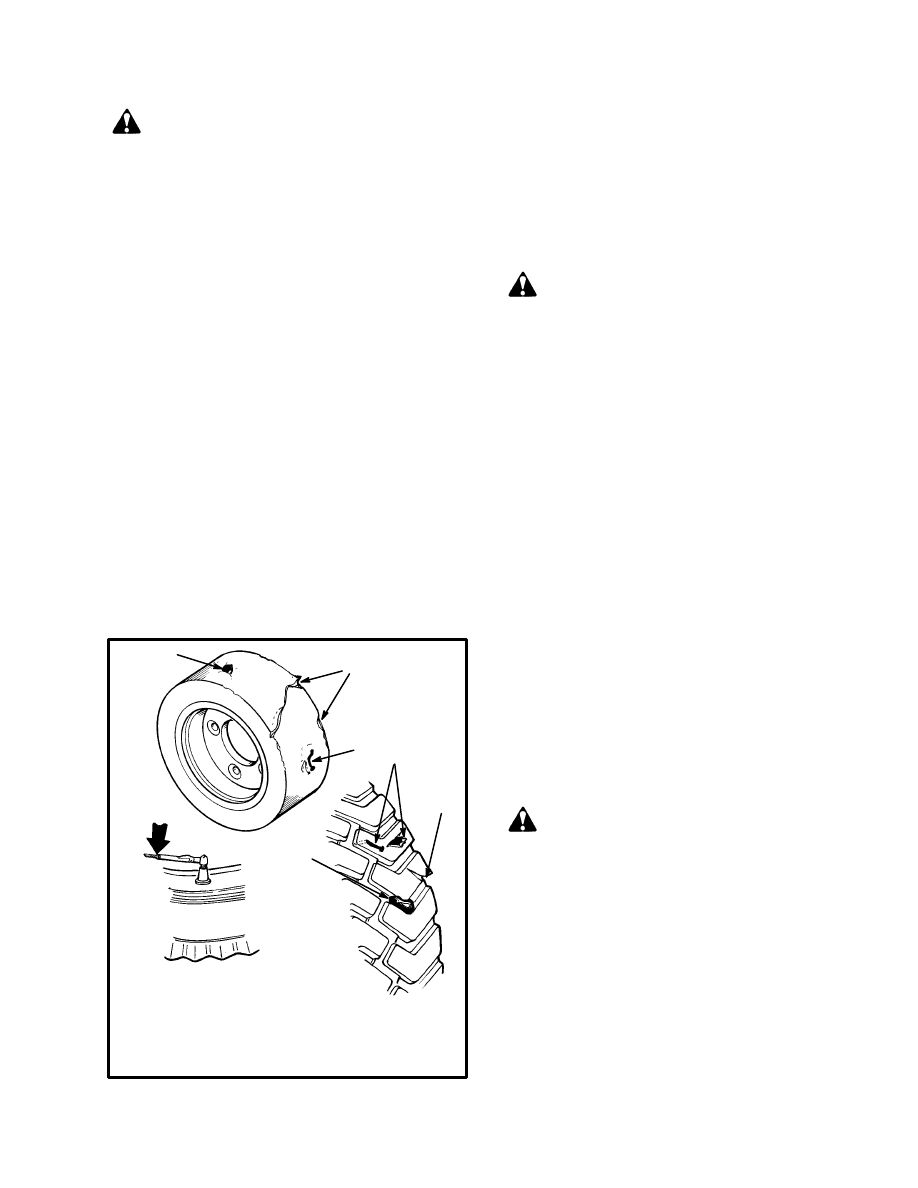
Tires and Wheels (See FIGURE 9.)
WARNING
Air pressure in tires can cause tire and wheel parts to
explode. This action can cause serious injury or
death.
Remove all of the air from the tires before the tires
are removed from the lift truck.
If a tire has less than 80% of the correct air pressure,
completely remove the air pressure from the tire.
Remove the tire from the lift truck. Add air pressure
to the tire only in a safety cage. See the procedures in
Add Air To The Tires.
When air is added to the tires, use a remote air chuck.
The person adding air must stand away and to the
side and not in front of the tire.
If the lift truck has pneumatic tires, keep the tires at the
correct air pressure (see the nameplate). Check the air
pressure with a gauge when the tires are cold. If it is nec-
essary to add air to a tire that is warm, check the other tire
on the same axle and add air to the tire that has low pres-
sure so that the air pressures are equal. The air pressure
of the warm tires must always be equal to or greater than
the specification for air pressure for cold tires.
9447
11402
3
2
1
1
1
2
1
1. CHECK FOR DAMAGE AND
REMOVE NAILS, GLASS,
METAL AND OTHER OBJECTS
2. MAKE EDGES SMOOTH
3. CHECK THE TIRE PRESSURE
(PNEUMATIC TIRES)
FIGURE 9. CHECK THE TIRES
Check the tires for damage. Inspect the tread and re-
move any objects that will cause damage. Check for
bent or damaged rims. Check for loose or missing parts.
Remove any wire, straps or other material wrapped
around the axle.
Make sure that the wheel nuts are tight. Tighten the
wheel nuts in a cross pattern to the correct torque value
shown in the MAINTENANCE SCHEDULE.
CAUTION
When the wheels have been installed, check all wheel
nuts after 2 to 5 hours of operation. Tighten the nuts
in a cross pattern to the correct torque value shown
in the MAINTENANCE SCHEDULE. When the
nuts stay tight for eight hours, the interval for check-
ing the torque can be extended to 350 hours.
Forks, Adjustment
Hook forks are connected to the carriage by hooks and
lock pins. See FIGURE 10. These lock pins are installed
through the top fork hooks and fit into slots in the top
carriage bar. Adjust the forks as far apart as possible for
maximum support of the load. Hook forks will slide
along the carriage bars to adjust for the load to be lifted.
Raise the lock pin in each fork to slide the fork on the
carriage bar. Make sure the lock pin is engaged in the
carriage bar to lock the fork in position after the width
adjustment is made.
Forks, Removal And Installation
A fork can be removed from the carriage for replace-
ment of the fork or other maintenance.
WARNING
Do not try to move a fork without a lifting device.
Each hook fork for these lift trucks can weigh 35 kg
to 180 kg (80 to 395 lb).
Hook Fork (Removal). Slide a hook fork to the fork re-
moval notch on the carriage. See FIGURE 10. Lower
the fork onto blocks so that the bottom hook of the fork
moves through the fork removal notch. See
FIGURE 11. Lower the carriage further so that the top
hook of the fork is disengaged from the top carriage bar.
Move the carriage away from the fork, or use a lifting
device to move the fork away from the carriage. Lay the
fork on its side so that it cannot fall and cause injury.
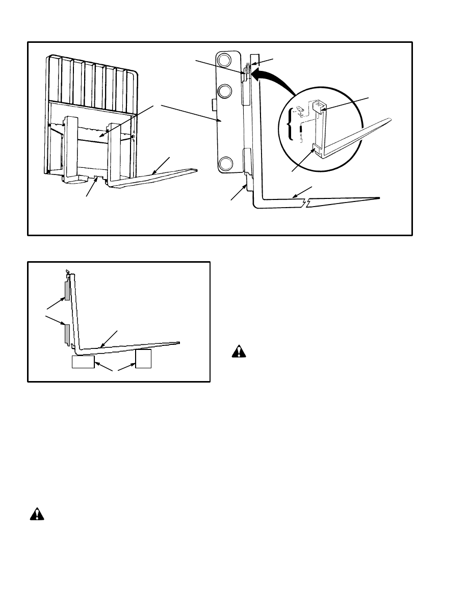
10
1545
2
5
1
4
3
2
3
3
3
4
1. FORK REMOVAL NOTCH
2. FORK
3. HOOK
4. LOCK PIN ASSEMBLE
5. CARRIAGE
FIGURE 10. HOOK FORK
FIGURE 11. REMOVE A HOOK FORK
ÉÉÉ
ÉÉÉ
ÉÉ
ÉÉ
ÉÉ
1
3
2
1. CARRIAGE BARS
2. HOOK FORK
3. BLOCKS
Hook Fork (Installation). Move the fork and carriage
so that the top hook on the fork can engage the upper car-
riage bar. Raise the carriage to move the lower hook
through the fork removal notch. Slide the fork on the
carriage so that both upper and lower hooks engage the
carriage. Engage the lock pin with a notch in the upper
carriage bar.
SAFETY LABELS
WARNING
Safety labels are installed on the lift truck to give in-
formation about operation and possible hazards. It
is important that all safety labels are installed on the
lift truck and can be read.
Check that all safety labels are installed in the correct lo-
cation on the lift truck. See the PARTS MANUAL or
the FRAME section of the SERVICE MANUAL for
the correct location of the safety labels. See the
FRAME section for the installation procedure.
HOW TO MAKE CHECKS WITH THE KEY
SWITCH ON
WARNING
FASTEN YOUR SEAT BELT! The seat belt is
installed to help the operator stay on the truck if the
lift truck tips over. IT CAN ONLY HELP IF IT IS
FASTENED.
Make sure the area around the lift truck is clear before
moving the lift truck. Always look in the direction that
you intend to move the lift truck. Be careful when mak-
ing the checks.
Gauges and Horn
NOTE: The control fuse is under the floor plate (EV–1)
or in the electrical compartment (EV–100 or EV–200).
1. Check the operation of the gauges and horn. The horn
will operate when the key switch is OFF. The hour meter
will operate when the key switch is ON and the seat
switch is closed.
2. The battery indicator will operate when the key
switch is ON. If the battery is replaced with a fully

11
charged battery, the battery indicator will not indicate a
fully charged battery until the lift truck has operated for
a short period of time. Tilt the mast backward until the
hydraulic relief valve operates. The battery indicator
will then indicate correctly. A battery indicator without
“lift interrupt” will only indicate battery charge when
the hydraulic relief valve operates.
Lift System Operation
WARNING
Lower the lift mechanism completely. Never allow
any person under a raised carriage. Do not put any
part of your body in or through the lift mechanism
unless all parts of the mast are completely lowered,
the key switch is in the OFF position and the key is
removed.
Before making any repairs, use blocks and chains on
the mast weldments and carriage so that they can not
move. Make sure the moving parts are attached to a
part that does not move.
Do not try to locate hydraulic leaks by putting hands
on pressurized hydraulic components. Hydraulic oil
can be injected into the body by pressure.
1. Check for leaks in the hydraulic system. Check the
condition of the hydraulic hoses and tubes.
2. Slowly raise and lower the mast several times without
a load. The mast components must raise and lower
smoothly in the correct sequence. The carriage raises
first, then the inner weldment and the intermediate
weldment (three–stage masts only). The inner weld-
ment(s) and the carriage must lower completely.
NOTE: Some parts of the mast move at different speeds
during raising and lowering.
3. Put a capacity load on the forks. Tilt the mast back-
wards. Raise the carriage until the rods of the main lift
cylinders extend 60 to 90 cm (2 to 3 ft), then lower the
carriage. The components of the mast must move
smoothly in the correct sequence.
4. With the load lowered, tilt the mast backward and for-
ward. The mast must tilt smoothly and both tilt cylinders
must stop evenly.
5. Check that the controls for the attachment operate the
functions of the attachment. (See symbols by each of the
controls.) Make sure all of the hydraulic lines are con-
nected correctly and do not leak.
Service Brakes
Check the operation of the service brakes. Push on the
brake pedal. The brake pedal must stop firmly and must
not move slowly down after the brakes are applied. The
service brakes must apply equally to both drive wheels.
The service brakes must not pull the lift truck to either
side of the direction of travel when they are applied. The
service brakes are automatically adjusted when the
brakes are applied and the lift truck changes direction.
WARNING
Loss of fluid from the master cylinder indicates a
leak. This condition can cause brake failure. The
result can be material damage or personal injury.
Repair the brake system before the lift truck is used.
Replace the brake fluid in the system if there is dirt,
water, or oil in the system.
Parking Brake
Check the operation of the parking brake. The parking
brake, when correctly adjusted, will hold the lift truck
with a capacity load on a 15% grade [1.5 metre rise in 10
metres (1.5 ft rise in 10 ft)]. Turn the knob on the end of
the hand lever to adjust the parking brake. Do not tighten
the adjustment so that the brakes are applied when the
hand lever is released.
Some lift trucks are equipped with an additional brake
that is actuated automatically when the operator leaves
the seat. When correctly adjusted, this brake will hold
the lift truck with a capacity load on a 15% grade. Make
sure the service brakes operate correctly before check-
ing the operation of the seat brake. If the brake does not
hold the lift truck on the grade, the seat brake must be
adjusted by authorized service personnel according to
the procedure in the SERVICE MANUAL.
Steering System
WARNING
The lift truck has hydraulic power steering. Steering
can be difficult when the power steering pump is not
operating.
Make sure that the steering system operates smoothly
and gives good steering control.
12
EVERY 350 HOURS OR TWO MONTHS
Do these procedures in addition to the 8–hour checks.
HYDRAULIC TANK BREATHER
Check and clean the hydraulic tank breather. Clean the
breather when it is dirty and will not permit the easy pas-
sage of air. The breather is on a pipe near the hydraulic
filter.
STEERING TIE RODS,
E/J1.25–1.75XL (E25–35XL) and
J2.00–3.00XL (J40–60XL)
Use multi–purpose grease to lubricate the four fittings
on the steering tie rods.
DIFFERENTIAL AND SPEED REDUCER
(See FIGURE 12.)
WARNING
Do not work under a raised carriage. Lower the
carriage or use a chain to prevent the carriage and
the inner or intermediate weldments from lowering
when doing maintenance. Make sure that the
moving parts are attached to parts that can not
move.
Check the oil level at the fill plug in the differential
housing. The oil level must be even with the bottom of
the hole. Add oil if the oil level is low. Install and tighten
the plug.
11522
1. FILL PLUG
2. DIP STICK
2
1
FIGURE 12. DIFFERENTIAL
WHEEL NUT TORQUES
Tighten wheel nuts as required. See Install The Wheels
and SPECIFICATIONS.
STEERING AXLE SPINDLES,
E/J2.00–3.00XL (E/J40–60XL)
E3.50–5.50XL (E70–120XL)
Use multi–purpose grease to lubricate the king pins in
the steering axle. A grease fitting is at the end of each
king pin on the bottom of the steering axle.
MAST (See FIGURE 13.)
CAUTION
DO NOT use steam or high–pressure water to clean
the load rollers or the lift chains. Steam and high–
pressure water can remove the lubrication from the
bearings in the load rollers. Water in the bearings of
the sheaves and the link pins of chains can also short-
en the service life of these parts.
WARNING
Cleaning solvents can be flammable and toxic, and
can cause skin irritation. When using cleaning
solvents, always follow the recommendations of the
manufacturer.
Parts of the lift mechanism can move and cause seri-
ous injury. Do not allow anyone under a raised car-
riage or forks. Do not put any part of your body in or
through the lift mechanism if any part of the lift
mechanism can move.
Before you reach into the lift mechanism:
•
Make sure that all parts of the lift mechanism
are completely lowered.
•
If the lift mechanism cannot be lowered com-
pletely, use blocks or chains on the mast weld-
ments and carriage so that they cannot move.
Use a chain to attach each moving part of the
lift mechanism to a part that does not move. If
blocks are used, make sure that blocks are
placed between each part that moves and the
ground. Operate the lift/lower control to
check that all parts will not move, but do not
allow the lift chains to become loose.
13
•
Turn the key switch to OFF. Remove the key.
1. Clean the mast assembly. Inspect the mast channels in
the areas where the rollers travel. If there are loose or
displaced metal particles, remove the metal particles.
WARNING
Metal particles can fall into the eyes during the oper-
ation of the mast. Failure to remove this loose mate-
rial can cause eye injury. Remove displaced metal
particles with a grinder if necessary.
2. Lubricate the sliding surfaces and the load roller sur-
faces along the full length of the channels as shown in
FIGURE 13. Only apply lubricant to surfaces that are
clean and dry. Only apply lubricant to the darker areas
like those indicated by 1 and 2.
1. LUBRICATE STRIP BEARINGS SURFACES
2. LUBRICATE LOAD ROLLER SURFACES
3. LOAD ROLLER
11632
1
2
3
UPPER LOAD
ROLLERS
LOWER LOAD
ROLLERS
2
2
FIGURE 13. LUBRICATE THE MAST
NOTE: Some applications will require more frequent
cleaning and lubrication of the mast assembly. DO NOT
use a lubricant–spray on the surfaces of the mast chan-
nels where the load rollers make contact. The use of the
correct lubricant is important! Use multi–purpose
grease (Hyster Part No. 3020381) or an equivalent
grease with 2% to 4% molybdenum disulfide. The load
rollers and sheaves have sealed bearings that do not need
additional lubrication.
3. Lubricate the pivots for the mast at the grease fittings
on the pivots or the pivot pins. Use multi–purpose
grease.
4. If a side–shift carriage is installed, lubricate the fit-
tings for the rollers or the sliding surfaces with multi–
purpose grease.
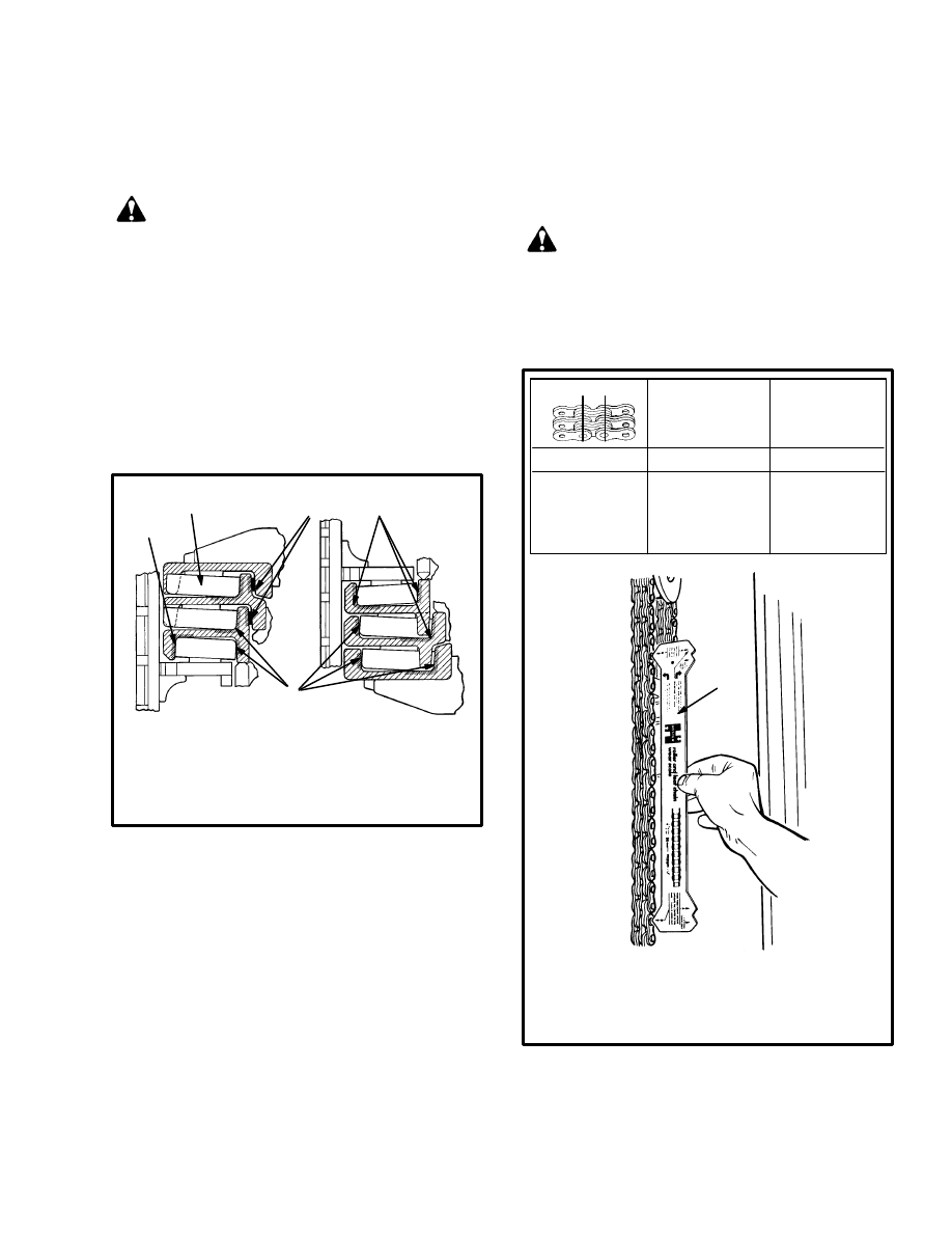
LIFT CHAINS (See FIGURE 14.)
Check for Wear
WARNING
Do not repair a worn or damaged lift chain. Replace
a worn or damaged lift chain with a new chain. If a
pair of lift chains is used in the mast, both lift chains
must be replaced.
1. CHAIN WEAR SCALE
NOTE: The instructions for measuring chain
wear are shown on the Chain Wear Scale.
Total length of
20 links(pitch)
of new chain
WEAR LIMIT
The maximum
length of 20 links
pitch
12174
1
12.7
(0.50)
254.0
(10.0)
261.6
(10.3)
15.9
(0.63)
317.5
(12.5)
327.0
(12.9)
19.1
(0.75)
381.0
(15.0)
392.4
(15.6)
25.4
(1.00)
508.0
(20.0)
523.3
(20.6)
mm
(inch)
mm
(inch)
mm
(inch)
FIGURE 14. CHECK THE LIFT CHAINS
If a section of chain is 3% longer than a similar section of
new chain, the chain is worn and must be replaced. If a
chain scale is available, check the lift chains as shown in
14
FIGURE 14. If a chain scale is not available, measure 20
links of chain. Measure from the center of a pin to the
center of another pin 20 links away. Compare the length
with the chart in FIGURE 14. Replace the chain if the
length of 20 links of the worn section is more than the
WEAR LIMIT.
Inspect the lift chains for edge wear where they pass
over the chain sheaves. Make sure the chain links are a
minimum of 95% (5% wear) of a chain link that is not
worn. See FIGURE 8.
Lubrication
Lubricate the lift chains with clean 30W engine oil or
Hyster Chain and Cable Lubricant (Hyster Part No.
171350).
NOTE: Lubrication or cleaning (see EVERY 2000
HOURS OR YEARLY) can be needed more frequently
in very dirty applications. Correct lubrication helps pro-
vide normal service life from these parts.
FORKS (See FIGURE 7.)
WARNING
Never repair damaged forks. Do not heat, weld, or
bend the forks. Forks are made of special steel using
special methods. Replace damaged forks.
1. Check the heel and attachment points of the forks with
a penetrant or magnetic particle inspection.
2. Measure the thickness of the forks at a vertical section
where there is no wear. This is dimension X. Now meas-
ure the thickness at the heel (4) of the fork. If the thick-
ness is not more than 90% of dimension X, replace the
fork.
3. Use clean engine oil as necessary to lubricate the
guides and locks for the forks.
BRAKE FLUID
WARNING
Loss of fluid from the master cylinder indicates a
leak. This condition can cause brake failure. The
result can be material damage or personal injury.
Repair the brake system before the lift truck is used.
Replace the brake fluid in the system if there is dirt,
water, or oil in the system.
Check the brake fluid in the reservoir for the master cyl-
inder. Add brake fluid as necessary. Use the brake fluid
shown in the MAINTENANCE SCHEDULE.
OTHER LUBRICATION
Lubricate hinges, pins, linkages, cables, pedals, and lev-
ers as necessary. Use SAE 30 oil, multi–purpose grease,
or silicone lubricant–spray (Hyster Part No. 328388) as
needed. See the MAINTENANCE SCHEDULE.
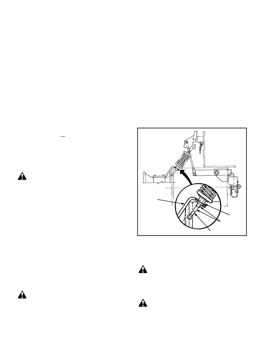
SEAT BRAKE
Adjust the seat brake for parking as described in section
100 SRM 284, THE FRAME. Lubricate the linkage for
the brake as shown in FIGURE 15. See the MAINTE-
NANCE SCHEDULE for lubricants.
1
LUBRICATE
2
3
1. BEARING
2. ROD
3. BRACKET
12675
FIGURE 15. LUBRICATE THE LINKAGE
FOR THE SEAT BRAKE
ELECTRICAL INSPECTION
WARNING
Disconnect the battery connector to prevent injury
from electric shock before you make any inspections
or repairs.
CAUTION
Never clean the components of the electrical system
with steam or high pressure water.
All models of the E/J1.25–1.75XL (E25–35XL) and the
E/J2.00–3.00XL (E/J40–60XL) series of electric lift

15
trucks are now equipped with the EV–100 SCR motor
controller. See FIGURE 19. These motor controllers are
made for Hyster Company by the General Electric Com-
pany.
The E3.50–5.50XL (E70–120XL) series of electric lift
trucks are equipped with the EV–100 or EV–200 SCR
traction motor controller made for Hyster Company by
the General Electric Company
.
See FIGURE 19.
Some units can be equipped with both types of motor
controllers. The E4.50–5.50XL (E100–120XL) lift
trucks are equipped with the EV–200 traction motor
controller because a larger traction motor is used in the
lift truck. These units can also have an EV–100 motor
controller and a contactor when two hoist pump motors
are installed.
The E3.50–4.00XL (E70–80XL) lift trucks will be
equipped with the EV–200 controller if the larger trac-
tion motor is installed as optional equipment.
The EV–100 and the EV–200 SCR motor controllers
have the same operation and use the same troubleshoot-
ing procedures. Many of the components are the same.
The EV–200 is required for the higher motor current
that the larger traction motor uses.
Additional information for the EV–100 and EV–200
motor controllers is available in the following sections:
•
EV–100LXT/LX/LXP AND EV–200LXT/LX
MOTOR CONTROLLER, & DIAGNOSTIC
HAND SET, 2200 SRM 460, Part No. 897409
•
EV–200 MOTOR CONTROLLER, Descrip-
tion And Operation, 2200 SRM 414, Part No.
897346
•
EV–100 MOTOR CONTROLLER, Descrip-
tion And Operation, 2200 SRM 287, Part No.
897069
•
EV–100 MOTOR CONTROLLER, Repairs
And Adjustments, Part No. 897070
•
EV–100 MOTOR CONTROLLER, Trouble–
shooting, 2200 SRM 312, Part No. 897094
•
DIAGRAMS, 8000 SRM 293, Part No. 897075
•
DIAGRAMS, 8000 SRM 416, Part No. 897348
NOTE: Electric lift trucks, “XL” series, manufac-
tured in Irvine, Scotland before November 1987
are equipped with a Cableform Mark XI motor
controller. The electric lift trucks manufactured in
Berea, Kentucky, U.S.A. are equipped with the
EV–100 motor controller made for Hyster Com-
pany by the General Electric Company. During
November 1987, a revision was made in the con-
figuration of the EV–100 motor controller and this
revised motor controller was installed in all elec-
tric lift truck, “XL” series, manufactured by Hys-
ter Company in Irvine and Berea after this date.
If your lift truck is equipped with a Cableform
Mark XI motor controller, additional information
is available in the following sections:
CABLEFORM MARK XI MOTOR
CONTROLLER, Description And Op-
eration, 2200 SRM 289, Part No. 897071
CABLEFORM MARK XI MOTOR
CONTROLLER, Troubleshooting And
Repairs, 2200 SRM 290, Part No. 897072
DIAGRAMS, 8000 SRM 314, Part No.
897096
MOTOR CONTROLLERS IN EARLIER
MODEL LIFT TRUCKS
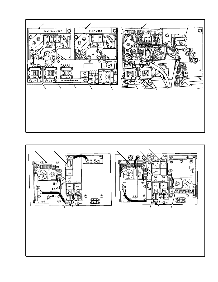
Contactors (See FIGURE 16., FIGURE 17.,
FIGURE 18. and FIGURE 19.)
The contactor contacts are made of special silver alloy.
The contacts will look black and rough from normal op-
eration. This condition does not cause problems with the
operation of the lift truck. Cleaning is not necessary. DO
NOT USE A FILE ON THE CONTACTS. DO NOT
LUBRICATE THE CONTACTS. Always replace the
contacts in sets. Check for equal spring tension if the
contacts do not wear evenly. See the ELECTRICAL
sections for replacement and adjustment procedures.
Motor Brushes
NOTE: The traction motor and the hydraulic pump mo-
tor are below the battery compartment. Remove the bat-
tery and the access panel to check the motors. The steer-
ing pump motor is on a vertical mount below the floor
plate. Remove the floor plates for access to the steering
pump.
16
1. Visually inspect the commutator and brushes every
350 hours. Make sure the surface of the commutator is
good and the operation of the motor is correct. Worn mo-
tor brushes must be replaced before they damage the
surface of the commutator.
Move the brush spring and remove a brush from the
brush holder. When the brush wears within approxi-
mately 1.5 mm (0.060 in) of where the brush wire joins
the brush, the brush must be replaced.
2. Some lift trucks are equipped with brush wear indica-
tors on the traction and hydraulic motors. The brush
wear indicators give a signal on the LED display panel
on the instrument panel. The sensor wires for the brush
wear indicators are an insert in the brush material when
it is made. When the brush wears within 1.5 mm (0.060
in) of the brush wire, the insulation between the sensor
wire and the brush material is destroyed. The connec-
tion between the brush and the sensor causes the LED
indicator to illuminate. The brush wear indicators will
not indicate a damaged commutator nor indicate a motor
malfunction. Visually inspect the commutator and
brushes on lift trucks with brush wear indicators also.
3. Inspect the brush holders for burns or damage. Make
sure the brush holder is fastened tightly to the mounts at
the end of the motor. Make sure the brushes will move
freely and smoothly in the brush holders.
4. Check the brush springs for damage from heat and
corrosion. Replace a damaged brush spring.
See the section DC MOTOR MAINTENANCE, 620
SRM 294, for additional information to inspect the
commutator and brushes.
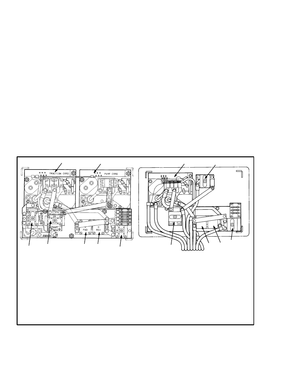
12173
12124
FIGURE 16. TYPICAL CONFIGURATIONS OF THE EV–100LX MOTOR CONTROLLER
(AFTER NOVEMBER 1987)
1
2
3
4
1. CONTROL CARD, TRACTION, WITH REGENERATIVE BRAKING (TX or TT)
2. CONTROL CARD, TRACTION, WITHOUT REGENERATIVE BRAKING (TX)
3. CONTROL CARD, SCR CONTROL FOR HYDRAULIC PUMP MOTOR (PX)
4. CONTACTOR, HYDRAULIC PUMP MOTOR
5. CONTACTOR, REGENERATIVE BRAKING
6. CONTACTOR, 1A
7. CONTACTOR, FORWARD DIRECTION
8. CONTACTOR, REVERSE DIRECTION
9. CONTACTOR, FIELD WEAKENING
MOTOR CONTROLLER WITH REGENERATIVE
BRAKING, 1A BY–PASS, AND SCR
CONTROLLER FOR HYDRAULIC PUMP
MOTOR CONTROLLER WITH 1A BY–PASS,
AND CONTACTOR CONTROL FOR HYDRAULIC
PUMP
5
6
6
7
7
8
8
9
9
17
11482
FIGURE 17. TYPICAL CONFIGURATIONS OF THE EV–100 CONTROLLER
(BEFORE NOVEMBER 1987)
1. TRACTION CARD REGENERATIVE BRAKING (R1)
2. TRACTION CARD WITHOUT REGENERATIVE
BRAKING (T1)
3. EV–100 CONTROL, HYDRAULIC PUMP MOTOR
4. CONTACTOR, HYDRAULIC PUMP MOTOR
11531
MOTOR CONTROLLER WITH REGENERATIVE
BRAKING, 1A BY–PASS, AND SCR
CONTROLLER FOR HYDRAULIC PUMP
MOTOR CONTROLLER WITH 1A BY–PASS,
AND CONTACTOR CONTROL FOR HYDRAULIC
PUMP
5. CONTACTOR, REGENERATIVE BRAKING
6. CONTACTOR, 1A
7. CONTACTOR, FORWARD DIRECTION
8. CONTACTOR, REVERSE DIRECTION
9. CONTACTOR, FIELD WEAKENING
3
1
2
4
9
8
7
6
5
7
8
6
SCR TRACTION CONTROL WITH REGENERATIVE
BRAKING AND SCR HYDRAULIC CONTROL
11581
SCR TRACTION CONTROL ONLY
FIGURE 18. CABLEFORM CONTROLLERS
*LIFT TRUCKS THAT HAVE A HYDRAULIC PUMP
CONTACTOR DO NOT HAVE A 1A CONTACTOR
OR A REGENERATIVE BRAKING CONTACTOR.
1
1. TRACTION CONTROLLER WITH
REGENERATIVE BRAKING
2. TRACTION CONTROLLER WITHOUT
REGENERATIVE BRAKING
3. MOTOR CONTROLLER, HYDRAULIC
PUMP MOTOR
4. CONTACTOR, HYDRAULIC PUMP MOTOR
5. CONTACTOR, REGENERATIVE BRAKING
6. CONTACTOR, 1A
7. CONTACTOR, FORWARD DIRECTION
8. CONTACTOR, REVERSE DIRECTION
9. CONTACTOR, FIELD WEAKENING
2
4
5
6
3
7
8
7
8
18
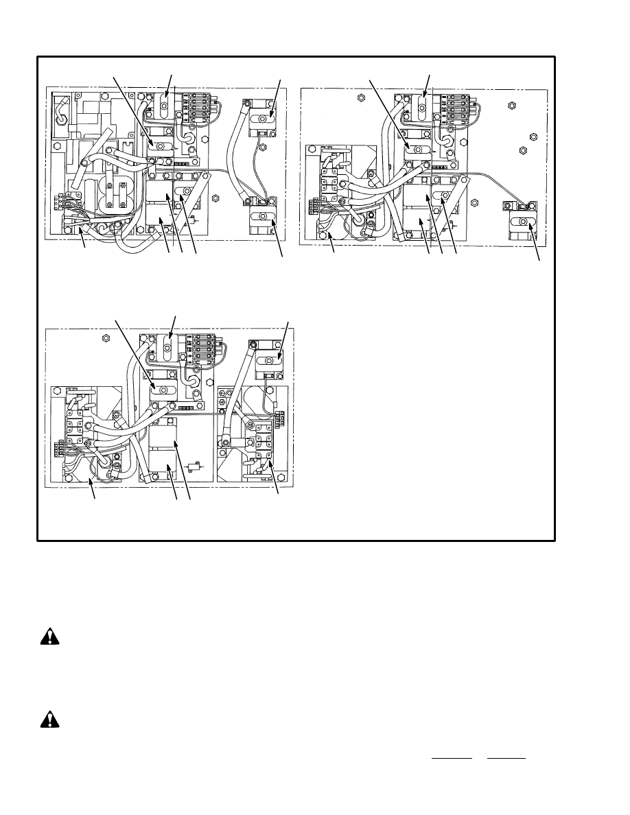
FIGURE 19. EV–200 AND EV–100 MOTOR CONTROLLERS FOR E3.50–5.50XL (E70–120XL)
EV–200 TRACTION CONTROLLER
WITH CONTACTOR HYDRAULIC
CONTROL (2 PUMP MOTORS)
EV–100 TRACTION CONTROLLER
WITH CONTACTOR HYDRAULIC
CONTROL (1 PUMP MOTOR)
EV–100 TRACTION CONTROLLER AND
EV–100 HYDRAULIC PUMP CONTROLLER
12275
1. TRACTION CONTROLLER WITH
REGENERATIVE BRAKING
2. MOTOR CONTROLLER, HYDRAULIC
PUMP MOTOR
3. CONTACTOR, HYDRAULIC PUMP MOTOR
4. CONTACTOR, REGENERATIVE BRAKING
5. CONTACTOR, 1A
6. CONTACTOR, FORWARD DIRECTION
7. CONTACTOR, REVERSE DIRECTION
8. CONTACTOR, FIELD WEAKENING
(NOT ON ALL UNITS)
4
4
4
3
3
3
3
2
1
1
1
5
5
5
6 7
6 7
6 7
8
8
EVERY 2000 HOURS OR YEARLY
HYDRAULIC SYSTEM
WARNING
The hydraulic oil is HOT at operating temperature.
Do not permit the hot oil to contact the skin and
cause a burn.
CAUTION
Do not permit dirt to enter the hydraulic system
when the oil level is checked or the filter is changed.
Dirt can cause damage to components of the hydrau-
lic system.
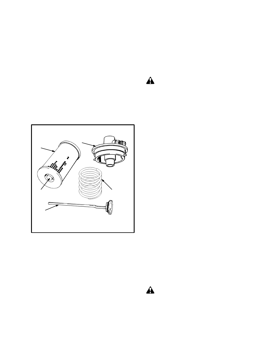
Change the Filter for the Hydraulic Oil
(See FIGURE 20.)
NOTE: Change the oil filter for the hydraulic system af-
ter the first 100 hours on new lift trucks.
1. Remove the floor plates. Clean the top of the hydrau-
lic tank in the area of the filter.
2. Follow the procedure in step 2. a. or step 2. b.:
19
a. E3.50–5.50XL (E70–120XL). Remove the nut,
retainer and wire clamp that hold the filter head
on the tank. Remove the filter head. Remove the
filter from the tank.
b. Other Models. Disconnect the hydraulic return
hose at the filter. Loosen the band clamps on the
rubber sealing ring. Turn the filter cap counter-
clockwise to disengage the two pins that hold the
filter cap in the hydraulic tank. A coil spring un-
der the filter holds the filter against the filter cap.
Remove the filter cap and then remove the filter.
NOTE: The hydraulic oil filter has a by–pass relief
valve that is part of the filter. Make sure the correct re-
placement filter with a by–pass relief valve is installed.
11521
1. FILTER
2. RELIEF VALVE
3. DIPSTICK
4. FILTER CAP
5. SPRING
1
2
3
4
5
FIGURE 20. HYDRAULIC FILTER
COMPONENTS SHOWN FROM
E2.00–3.00XL(E40–60XL) UNITS
Change the Hydraulic Oil
Put the lift truck on a level surface. Lower the mast. Put a
drain pan with a 25 litre (26 qt) capacity under the hy-
draulic tank. Disconnect the hydraulic hose from the hy-
draulic tank to the steering pump and drain the oil into
the drain pan. (The quantity of oil is according to the size
of the mast and the optional hydraulic equipment.)
When the oil has drained, connect the hydraulic hose.
Fill the hydraulic tank with the correct oil after the filter
is installed. See the MAINTENANCE SCHEDULE.
DIFFERENTIAL AND SPEED REDUCER
Remove the plug from the bottom of the differential
housing to drain the oil. See the MAINTENANCE
SCHEDULE (Item 17) for the correct lubricant. Fill the
differential and speed reducer so that the oil level is even
with the fill plug or the “FULL” mark on the dipstick.
SERVICE BRAKES
WARNING
Brake linings contain asbestos or other fibers.
Breathing the dust from these brake linings is a can-
cer or lung disease hazard. Do not create dust! Do not
clean brake parts with compressed air or by brush-
ing. Use vacuum equipment approved for asbestos
dust or follow the cleaning procedure in this section.
When the brake drums are removed, do not create
dust.
Do not sand, grind, chisel, hammer or change linings
in any way that will create dust. Any changes to
brake linings must be done in a restricted area with
special ventilation. Protective clothing and a respira-
tor must be used.
Cleaning Procedures:
a. Do not release brake lining dust from the brake
linings into the air when the brake drum is re-
moved.
b. Use a solvent approved for cleaning of brake
parts to wet the lining dust. Follow the instruc-
tions and cautions of the manufacturer for the use
of the solvent. If a solvent spray is used, do not
create brake lining dust with the spray.
c. When the brake lining dust is wet, clean the parts.
Put any cloth or towels in a plastic bag or an air-
tight container while they are still wet. Put an
“ASBESTOS” warning label on the plastic bag or
airtight container.
d. Any cleaning cloths that will be washed must be
cleaned so that fibers are not released into the air.
CAUTION
Do not use an oil solvent to clean the wheel cylinder.
Use a solvent approved for cleaning of brake parts.
Do not permit oil or grease in the brake fluid or on
the brake linings.

20
Check the brake lining and parts of the brake assembly
for wear or damage. See the BRAKE SYSTEM section
for the removal and installation procedures of the drive
wheels and hubs. If the brake linings or brake shoes are
worn or damaged, they must be replaced. Brake shoes
must be replaced in complete sets. Inspect the brake
drums for cracks or damage. Replace any damaged
parts.
NOTE: Additional information can be found in the sec-
tion of the SERVICE MANUAL:
•
THE BRAKE SYSTEM, 1800 SRM 315
for models E/J1.25–1.75XL (E25–35XL) and E/
J2.00–3.00XL (E/J40–60XL)
•
THE BRAKE SYSTEM, 1800 SRM 338
for models E3.50–5.50XL (E70–120XL)
CONTACTORS
Always replace the contacts of a contactor as a complete
set. See the ELECTRICAL sections for replacement
and adjustment procedures.
WHEEL BEARINGS
Steer Wheels, Lubrication
Lubricate the wheel bearings in the hubs for the steer
wheels with multi–purpose grease. Do the following
procedure to install the hubs:
a. Install the hub and bearings on the spindle.
b. Install the castle nut. Tighten the castle nut to 200
N.m (150 lbf ft) while rotating the wheel and hub.
Loosen the nut until the wheel rotates freely and
the bearings are not loose. Tighten the nut to 35
N.m (25 lbf ft) and install the cotter pin at the
closest slot in the nut. Install the cap for the bear-
ings.
Drive Wheels, Lubrication
NOTE: Additional information can be found in the sec-
tion of the SERVICE MANUAL:
•
DRIVE AXLE, SPEED REDUCER AND
DIFFERENTIAL, 1400 SRM 285
for models E/J1.25–1.75XL (E25–35XL)
and E/J2.00–3.00XL (E/J40–60XL)
•
DRIVE AXLE, SPEED REDUCER AND
DIFFERENTIAL, 1400 SRM 413
for models E3.50–5.50XL (E70–120XL)
Lubricate the inner wheel bearings in the hubs for the
drive wheels with multi–purpose grease. See the section
for the DRIVE AXLE or the BRAKE SYSTEM for the
procedures to remove and install the drive wheels and
hubs.
LIFT CHAINS
WARNING
Cleaning solvents can be flammable and toxic, and
can cause skin irritation. When using cleaning
solvents, always follow the recommendations of the
manufacturer.
Compressed air can move particles so that they
cause injury to the user or to other personnel. Make
sure that the path of the compressed air is away from
all personnel. Wear protective goggles or a face
shield to prevent injury to the eyes.
Remove the lift chains. Clean the lift chains by soaking
them in a solvent that has a petroleum base for at least 30
minutes. Use compressed air to completely dry the
chains when they are clean.
Lubricate the lift chains by soaking them in 30W engine
oil for at least 30 minutes. Remove the chains from the
oil. Hang the chains for one hour so that excess oil will
drain from the chains.
21
GENERAL PROCEDURES
HOW TO CHARGE THE BATTERY
WARNING
If the lift truck was operated with a low battery,
inspect all contactors for welded contacts BEFORE
you connect a charged battery. The lift truck can not
be controlled if contacts are welded. This condition
can cause personal injury when the battery is
connected.
CAUTION
Never connect the battery charger plug to the plug of
the lift truck. You can damage the electronic
controller. Make sure the battery charger voltage is
the correct voltage for the battery.
WARNING
The acid in the electrolyte can cause injury. Use
water to flush the area and make the acid neutral
with a water and soda solution. Acid in the eyes must
be flushed with water. Batteries generate explosive
fumes when they are being charged. Keep fire,
sparks and burning material away from the battery
charger area. Avoid sparks from the battery
connections. Charge batteries only in the special
area for charging batteries. When the battery is
being charged, keep the vent caps clear. The battery
charger area must have ventilation so that explosive
fumes are removed. Open the battery cover on a
covered battery. Disconnect the battery when doing
cleaning and maintenance.
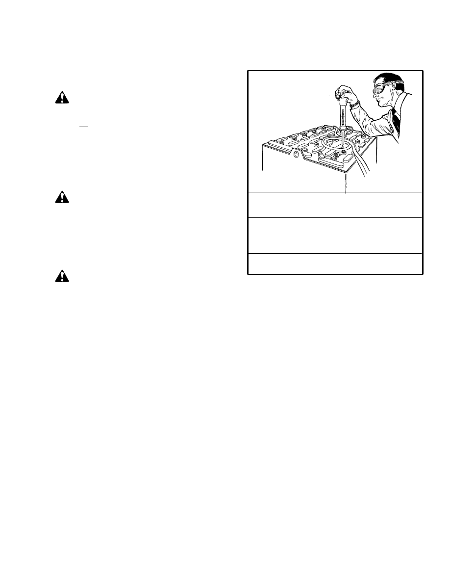
Correct use of the hydrometer (See FIGURE 21.) and
proper operation of the battery charger is important.
Follow the instructions of the charger manufacturer.
Never let the battery discharge below the minimum
value given by the battery manufacturer. A fully charged
battery will have a specific gravity of 1.265 to 1.310 at
25
°
C (77
°
F). Never charge a battery at a rate that will
raise the electrolyte temperature above 49
°
C (120
°
F).
Never let a battery stay discharged for long periods.
SPECIFIC
GRAVITY
READING
ELECTRO–
LYTE
TEMP.
POINTS
CORRECTION CORRECT
VALUE
1.210
1.210
1.210
1.210
+0.003
+0.001
0.000
–0.004
1.213
1.211
1.210
1.206
31
°
C (87
°
F)
27
°
C (80
°
F)
25
°
C (77
°
F)
18
°
C (64
°
F)
FIGURE 21. CHECK SPECIFIC GRAVITY
11034
+0.001 or –0.001 for each 2 degrees C
from the 25 degree base value.
1. NORMAL CHARGE: This charge is the charge that
is normally given to a battery that is discharged from
normal service. Many users give this charge at a regular
interval based on usage. This practice will keep the bat-
tery fully charged if the battery is not discharged below
the limit. Always use a hydrometer (TABLE 2) to check
the battery if the interval charge cycle is used. Frequent
charging of a battery that has 2/3 of a full charge or more
can decrease battery life.
2. EQUALIZING CHARGE: This charge is at a low rate
and balances the charge in all of the cells. The equalizing
charge is normally given approximately once a month. It
is a charge at a slow rate for three to six hours in addition
to the regular charging cycle.
DO NOT give an equalizing charge more than once a
week. The most accurate specific gravity measurements
for a charged battery will be after an equalizing charge.
If the specific gravity difference is more than 0.020 be-
tween cells of the battery after and equalizing charge,
there can be a damaged cell. Consult your battery dealer.
NOTE: Many users have battery chargers that can fol-
low a program to automatically charge a battery accord-
ing to recommendations of the battery manufacturer.

22
Use the recommendations of the battery manufacturer
for charging the battery.
Also see the section THE INDUSTRIAL BATTERY,
2240 SRM 1, for additional information on the charging
and maintenance of a battery.
HOW TO CHANGE THE BATTERY
WARNING
Batteries are heavy and can cause an injury. Use care
to avoid injury. Do NOT put hands, arms, feet and or
legs between the battery and a solid object.
Make sure the capacity of the crane and spreader
bar is greater than the weight of the battery. The
weight of the battery is normally shown on the
battery case. The maximum battery weight is shown
on the lift truck nameplate. The spreader bar must
NOT be made of metal or it must have insulated
straps.
The replacement battery must fit the battery area
correctly. Use spacers to prevent the battery from
moving horizontally in the battery compartment.
Make sure that the battery voltage and weight of the
replacement battery is correct as shown on the
nameplate.
Make sure the battery restraint is locked in the down
position before the lift truck is operated. On
E70–120XL units, make sure the battery retention
bar is lowered and locked under the seat.
Before connecting the battery, make sure the key
switch is in the OFF position and the parking brake
is set.
1. Disconnect the battery. Move the connector and ca-
bles so that they will not be damaged when the battery is
moved. Tilt the steering column forward and make sure
the detent engages to hold the steering column. Slide the
seat to the rear adjustment position. Release the lock on
the battery restraint and tilt the battery restraint and seat
to the up position. Make sure the battery restraint and the
seat are locked in the up position.
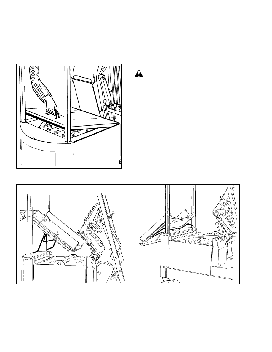
2. If the lift truck has a hood, open the hood from over
the battery. See FIGURE 24. If the battery is not a cov-
ered battery, put an insulating cover over the battery. If
the lift truck has a battery retention bar, secure the bar in
the UP position.
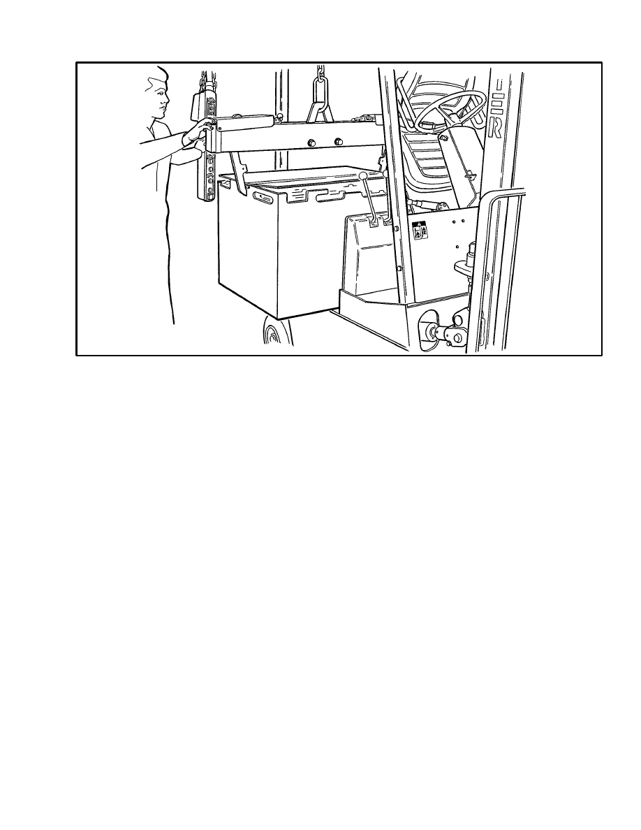
3. Use a spreader bar and crane to lift the battery from
the lift truck. See FIGURE 25. When a replacement bat-
tery is installed, make sure the battery fits the battery
compartment. Use spacers to prevent the battery from
moving more than a total of 13 mm (0.5 in) in any one
horizontal direction. See FIGURE 22.
WARNING
Correct operation of the battery restraint system
requires that the battery does not move more than 13
mm (0.5 in). Make sure the battery spacers are
correctly adjusted. Use only spacers supplied with
the truck.
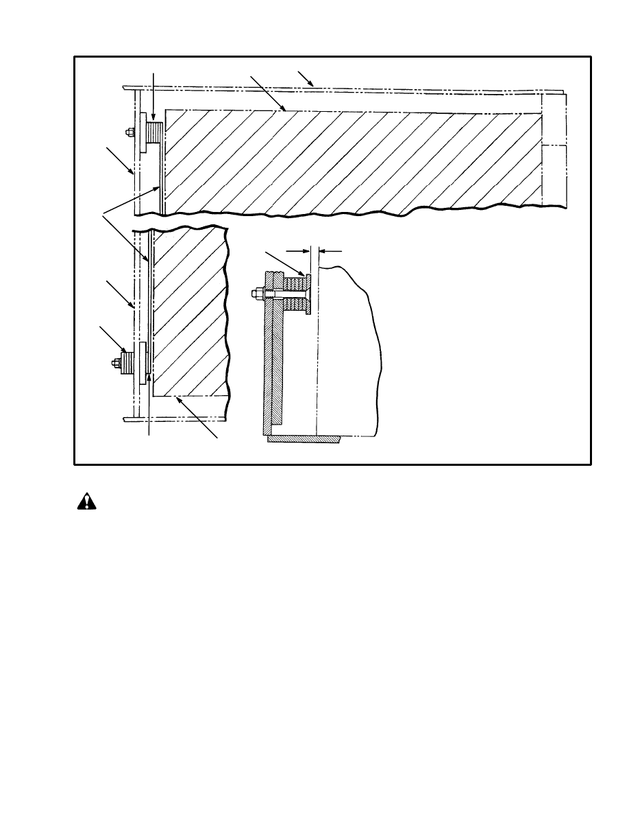
4. The lift trucks are equipped with adjustable spacers in
the battery compartment. See FIGURE 22. Add or re-
move shims from under the front spacer bar to control
the movement of the battery in the forward and back-
ward directions. Install an equal number of shims at
each capscrew. Install the unused shims under the nuts
of the capscrews (outside battery compartment). The
spacers on each side of the battery can be adjusted to
control the movement of the battery from side to side.
Access to the nuts for the spacers for the sides of the bat-
tery is under the frame near the steer tires. Tighten all
capscrews. It can be necessary to install the side spacers
facing the opposite direction for some batteries. If the
spacers can not be adjusted for a battery that is specified
for this lift truck, see your dealer for Hyster lift trucks
for the correct spacers.
23
FIGURE 22. BATTERY COMPARTMENT SPACERS
1. BATTERY COMPARTMENT
2. BATTERY
3. BULKHEAD
4. SPACER
5. SHIM
6. STORE ADDITIONAL SHIMS
IN FRONT OF BULKHEAD
FRONT SPACER
1
2
5
3
4
3
6
5
2
13 mm (1/2 in)
MAXIMUM
4
12711
WARNING
Make sure the capacity of the crane and spreader
bar is greater than the weight of the battery. The
weight of the battery is normally shown on the
battery case. The spreader bar must NOT be made of
metal or it must have insulated straps.
Batteries are heavy. Use care to avoid injury.
The replacement battery must fit the battery
compartment so that the battery restraint system
operates correctly.
Make sure the weight of the replacement battery is
within the maximum and minimum weights shown
on the nameplate.
Make sure that the voltage of the battery is the cor-
rect voltage for the lift truck.
Make sure that the key switch is in the OFF position
and the park brake is applied before you connect the
battery.
Make sure the battery restraint plate is locked in the
down position before the lift truck is operated. On
E3.50–5.50XL (E70–120XL) units, make sure the
battery retention bar is lowered and locked under
the seat.
1. Disconnect the battery. Move the connector and ca-
bles so that they will not be damaged when the battery is
moved. Tilt the steering column forward and make sure
it locks in position. Slide the seat to the rear adjustment
position. Release the lock on the battery restraint and tilt
the battery restraint and seat to the up position. Make
sure they are locked in the up position.
2. If the lift truck has a hood, open the hood from over
the battery (see FIGURE 23. and FIGURE 24.). If the
battery is not a covered battery, put an insulating cover
24
over the battery. Lift trucks without hoods must have a
battery cover. If installed, raise the battery retention bar
and put it in the up position.
NOTE: Lift trucks made in Irvine, Scotland have a dif-
ferent hood design (FIGURE 23.) than lift trucks made
in the U.S.A. (FIGURE 24.).
FIGURE 23. OPEN THE HOOD
(IRVINE DESIGN)
11537
3. Use a spreader bar and crane to lift the battery from
the lift truck. (See FIGURE 25.) When a replacement
battery is installed, make sure the battery fits the battery
compartment. Use the spacers designed by Hyster Com-
pany to prevent the battery from moving more than 13
mm (0.5 in) in any horizontal direction. See the OPER-
ATING MANUAL for installation of spacers.
WARNING
Correct operation of the battery restraint system
requires that the battery does not move more than 13
mm (0.5 in). Make sure that the battery spacers are
correctly adjusted.
FIGURE 24. OPEN THE HOOD
25
11449
FIGURE 25. CHANGE THE BATTERY
4. The lift trucks are equipped with adjustable spacers in
the battery compartment. Add or remove shims from
under the front spacer bar to control the movement of the
battery in the forward and backward directions. Install
an equal number of shims at each capscrew. Install the
unused shims under the nuts of the capscrews (outside
battery compartment). The spacers on each side of the
battery can be adjusted to control the movement of the
battery from side to side. Access to the nuts for the spac-
ers for the sides of the battery is under the frame near the
steer tires. Tighten all capscrews. It can be necessary to
install the side spacers facing the opposite direction for
some batteries. If the spacers can not be adjusted for a
battery that is specified for this lift truck, see your dealer
for Hyster lift trucks for the correct spacers.
26
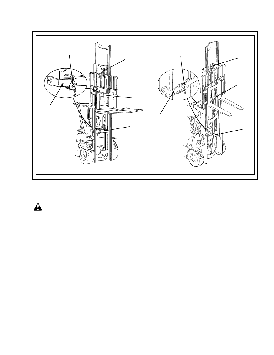
SAFETY PROCEDURES WHEN WORKING NEAR THE MAST (1 of 2)
WARNING
Mast parts are heavy and can move. Distances between parts are small. Serious
injury or death can result if part of the body is hit by parts of the mast or the carriage.
•
Never put any part of the body into or under the mast or carriage unless all parts are completely
lowered or a safety chain is installed. Also make sure that the power is off and the key is removed.
Put a “DO NOT OPERATE” tag in the operator’s compartment. Disconnect the battery on electric
lift trucks and put a tag or lock on the battery connector.
•
Be careful of the forks. When the mast is raised, the forks can be at a height to cause an injury.
•
DO NOT climb on the mast or lift truck at any time. Use a ladder or personnel lift to work on the
mast.
•
DO NOT use blocks to support the mast weldments nor to restrain their movement.
•
Mast repairs require disassembly and removal of parts and can require removal of the mast or
carriage. Follow the repair procedures in the correct Service Manual for the mast.
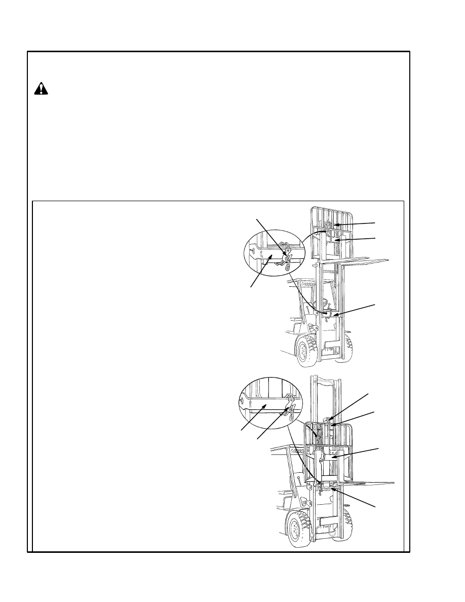
WHEN WORKING NEAR THE MAST ALWAYS:
•
Lower the mast and carriage completely. Push the
lift/lower control lever forward and make sure there is
no movement in the mast. Make sure that all parts of
the mast that move are fully lowered.
OR
•
If parts of the mast must be in a raised position, in-
stall a safety chain to restrain the moving parts of the
mast. Connect moving parts to a part that does not
move. Follow these procedures:
a. Put the mast in a vertical position.
b. Raise the mast to align the bottom crossmember of the
weldment that moves in the outer weldment with a
crossmember on the outer weldment (1). On the two–
stage and free–lift mast, the moving part is the inner
weldment (2). On the three–stage mast it is the intermedi-
ate weldment (3). On the four–stage mast it is the first
intermediate weldment (4).
c. Use a 3/8 inch minimum safety chain with a hook (5) to
fasten the crossmembers together so that the movable
member can not lower. Put the hook on the back side of
the mast. Make sure the hook is completely engaged with
a link in the chain. Make sure the safety chain does not
touch lift chains or chain sheaves, tubes, hoses, fittings or
other parts on the mast.
d. Lower the mast until there is tension in the safety chain
and the free–lift cylinder (6) (free–lift, three–stage and
four–stage masts only) is completely retracted. If running,
stop the engine. Apply the parking brake. Install a “DO
NOT REMOVE” tag on the safety chain(s).
e. Install another safety chain (3/8 inch minimum) be-
tween the top or bottom crossmember of the carriage (7)
and a crossmember on the outer weldment (8).
•
Apply the parking brake. After lowering or restraining
the mast, shut off the power and remove the key. Put a
“DO NOT OPERATE” tag in the operator’s compart-
ment. Disconnect the battery on electric lift trucks and
put a tag or lock on the battery connector.
1
2
5
8
The following procedures must be used when inspecting or working near the mast. Additional precautions
and procedures can be required when repairing or removing the mast. See the correct Service Manual sec-
tion for the specific mast being repaired.
TWO–STAGE
MAST
FREE–LIFT
MAST
7
8
5
1
2
7
6
27
SAFETY PROCEDURES WHEN WORKING NEAR THE MAST (2 of 2)
6
7
3
1
4
7
5
6
THREE–STAGE
MAST
FOUR–STAGE
MAST
1
5
CHECK FOR LEAKS IN THE LIFT AND
TILT SYSTEM
WARNING
Never allow any person under a raised carriage. Do
not put any part of your body in or through the lift
mechanism unless all parts of the mast are com-
pletely lowered, the key switch is in the OFF position
and the key is removed.
Before making any repairs, use blocks and chains on
the mast weldments and carriage so that they can not
move. Make sure the moving parts are attached to
the parts that can not move.
Do not try to find hydraulic leaks by putting your
hand on hydraulic components under pressure. Hy-
draulic oil can be injected into the body by pressure.
During test procedures for the hydraulic system, fas-
ten the load to the carriage with chains to prevent it
from falling. Keep all personnel away from the lift
truck during the tests.
Check the Lift Cylinders for Leaks
1. Operate the hydraulic system. Put a capacity load on
the forks and raise and lower the load several times.
Lower the load and tilt the mast forward and backward
several times. Check for leaks.
2. Raise the carriage and load so that the rods of the main
lift cylinders extend at least 60 cm (2 ft). If the carriage
lowers slowly with the control valve in the NEUTRAL
position, there are leaks inside the hydraulic system.
The maximum speed that the carriage is allowed to
lower is 50 mm (2 in) per 10 minutes when the hydraulic
oil is 30
°
C (90
°
F). If the oil temperature is 70
°
C
(160
°
F), the maximum speed that the carriage can lower
is 150 mm (6 in) per 10 minutes.
3. Check the lift cylinders for internal leaks. Remove the
load from the forks. Install a gate valve in the supply line
between the main control valve and the mast. Put a ca-
pacity load on the forks again. Raise the carriage and
load so that the rods of the main lift cylinders extend at
least 60 cm (2 ft). Close the gate valve. If the carriage or
mast weldments lower slowly, the seals in the lift cylin-
ders have leaks.

28
4. If the carriage and mast weldments do not move, open
the gate valve and check for movement again. If the car-
riage lowers when the valve is open, check for leaks in
the hydraulic lines or fittings. If no leaks are found, the
main control valve can have damage. Remove the load
from the forks.
Check the Tilt Cylinders for Leaks
1. Put a capacity load on the forks. Slowly tilt the mast
forward. If the mast continues to slowly tilt forward
when the control valve is in the NEUTRAL position,
there are leaks inside the hydraulic system. The maxi-
mum speed that the mast is allowed to tilt forward when
there are internal leaks in the lift system is 13 mm (0.50
in) per 10 minutes (measured at the tilt cylinder). The
maximum speed is measured when the hydraulic oil is
30
°
C (90
°
F). If the oil temperature is 70
°
C (160
°
F), the
maximum speed is 39 mm (1.5 in) per 10 minutes.
2. If the leak rate is greater than specifications, remove
the load from the mast. Install a valve between the port at
the front of the tilt cylinder and the hydraulic line. Put
the load on the forks again. Close the valve. If the mast
tilts slowly forward, the cylinder seals are leaking. Be
sure to check both tilt cylinders.
3. If the mast does not move, open the gate valve and
check for movement again. If the mast moves forward
when the gate valve is open, check for leaks in the hy-
draulic lines or fittings. If no leaks are found, the main
control valve can have damage. Remove the load from
the forks.
LIFT CHAIN ADJUSTMENTS
(See FIGURE 26.)
When the lift chains are correctly adjusted:
•
The tension will be the same on each chain of the
chain set. Check tension by pushing on both
chains at the same time.
•
The chain length will be correct.
•
The chains must travel freely through the com-
plete cycle.
1. When adjusting the two–stage or the free–lift mast,
start with step 2. Do the following steps first when ad-
justing the three–stage or the four–stage mast.
CAUTION
Adjust the four–stage mast carefully and keep it cor-
rectly adjusted. Incorrect adjustment can cause
damage to the free–lift hoses.
a. Adjust the chain anchors on the outer weldment
so that the top of the inner (or third) weldment is
level with the top of the outer weldment. The tol-
erance is +1.5 mm (0.06 in).
b. On the four–stage mast, adjust the chain anchors
on the second weldment so that the top of the in-
ner weldment is level with the top of the outer
weldment. Use the tolerance above.
2. Put a load equal to 80 to 90% of the capacity load on
the forks. Lower the forks as much as possible. Tilt the
mast fully backward.
3. See FIGURE 26. Check the amount that the bottom
carriage roller extends below the inner channel of the
mast. The carriage roller must not extend more than 1/3
of the roller diameter below the inner channel. If the ad-
justment is not correct, remove the load and adjust the
chain anchors. Make sure that each chain anchor is ad-
justed the same amount.
4. Remove the load from the forks. On the two–stage
mast, check the clearance of the carriage when the mast
is fully extended. On an mast with a free–lift cylinder,
make this check after extending the weldments a short
distance. The carriage stops must not touch the stop on
the top crossmember of the inner weldment. The chains
are too tight if the carriage touches the crossmember. Put
the mast in a vertical position and lower the carriage
completely. If the forks do not just touch the surface, the
chains are too tight. If the chains are too tight, adjust the
chain anchors. Make sure that each anchor is adjusted
the same amount.
NOTE: When the chain adjustments are complete,
make sure that the threads on the nuts of the chain an-
chors are completely engaged. Make sure that all of the
adjustment is not removed from the chain anchors. The
chain anchors must be able to move in their sockets.
HOW TO CHECK THE PMT CIRCUIT
WARNING
Some malfunctions can make the traction motor run
at high speed with no control by the speed controller.
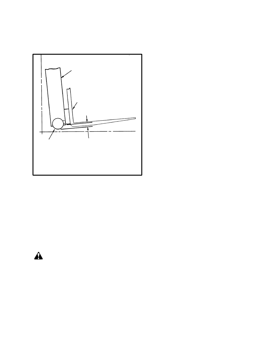
29
The PMT circuit prevents this operation if these
malfunctions occur. Do not operate the lift truck if
the PMT circuit does not operate correctly.
1. TILT MAST FULLY BACKWARD
2. CARRIAGE ROLLER
3. FORK
4. CARRIAGE ROLLER MUST NOT
EXTEND MORE THAN 34 mm (1.3 in)
BELOW THE MAST CHANNEL
1
2
3
4
4691
FIGURE 26. LIFT CHAIN ADJUSTMENTS
The Pulse Monitor Trip (PMT) circuit only functions if a
fault occurs. To check the circuit, we must cause a tem-
porary malfunction. Check the PMT circuit for correct
operation as follows:
1. Raise the drive wheels and put the lift truck on blocks.
See “How To Raise The Drive Tires” in this section. Re-
lease the parking brake.
WARNING
Disconnect the battery connector before making any
inspections or repairs. Personal injury or equipment
and tool damage can occur if the battery is not dis-
connected.
Do not touch the terminals of capacitor C1 of the
traction or lift control circuits. The charge on the ca-
pacitors can cause electrical shock and personal in-
jury. Use an insulated screwdriver or jumper wire to
make a short–circuit across the capacitor terminals
to discharge each capacitor. This will discharge the
capacitors to prevent electrical shocks.
2. Disconnect the battery, open the electrical compart-
ment and discharge capacitor(s) C1 on the SCR control
panels.
NOTE: The EV–200 motor controller has capacitor C2
connected in parallel with capacitor C1. Both capacitors
will be discharged.
3. Disconnect the gate lead from the SCR 5 for the trac-
tion circuit (white/violet wire). The gate lead has a
push–on connector. Make sure that the end of the lead
does not touch any other surface. See the DIAGRAMS
section that came with the lift truck for the location of
the gate lead.
4. Connect the battery.
5. Sit on the seat to close the seat switch and turn the key
to the “ON” position. Actuate the Monotrol control
pedal or the direction control lever and accelerator for
slow movement in the FORWARD or REVERSE direc-
tion.
6. Listen for the direction contactor to open. The trac-
tion system will not operate. The traction motor control-
ler will allow two power pulses before opening the con-
tactor.
7. As soon as the PMT circuit disables the traction con-
trol, turn the key to the “OFF” position. If the PMT cir-
cuit does not disable the traction control, replace the
control card. Correct procedures are in the SERVICE
MANUAL:
•
EV–100
MOTOR CONTROLLER, Repairs
and Adjustments, 2200 SRM 288,
for models E/J1.25–1.75XL (E25–35XL) and
E/J2.00–3.00XL (E/J40–60XL)
•
EV–200
MOTOR CONTROLLER,
Operation, Checks, Repairs and Adjust-
ments, 2200 SRM 414, for models
E3.50–5.50XL (E70–120XL)
•
ELECTRICAL SYSTEM, Checks and Ad-
justments, 2200 SRM 464,
for SitDrive
Models with EV–1, EV–1B,
EV–1W, EV–100 or EV–200 Motor Controllers
8. Disconnect the battery, open the electrical compart-
ment and discharge capacitors C1 (and C2 if installed)
on the SCR control panels as described in the earlier
WARNING.
9. Connect the SCR 5 gate lead. Connect the battery.
Raise the drive wheels and remove the blocks. Check for
normal operation of the traction motor.
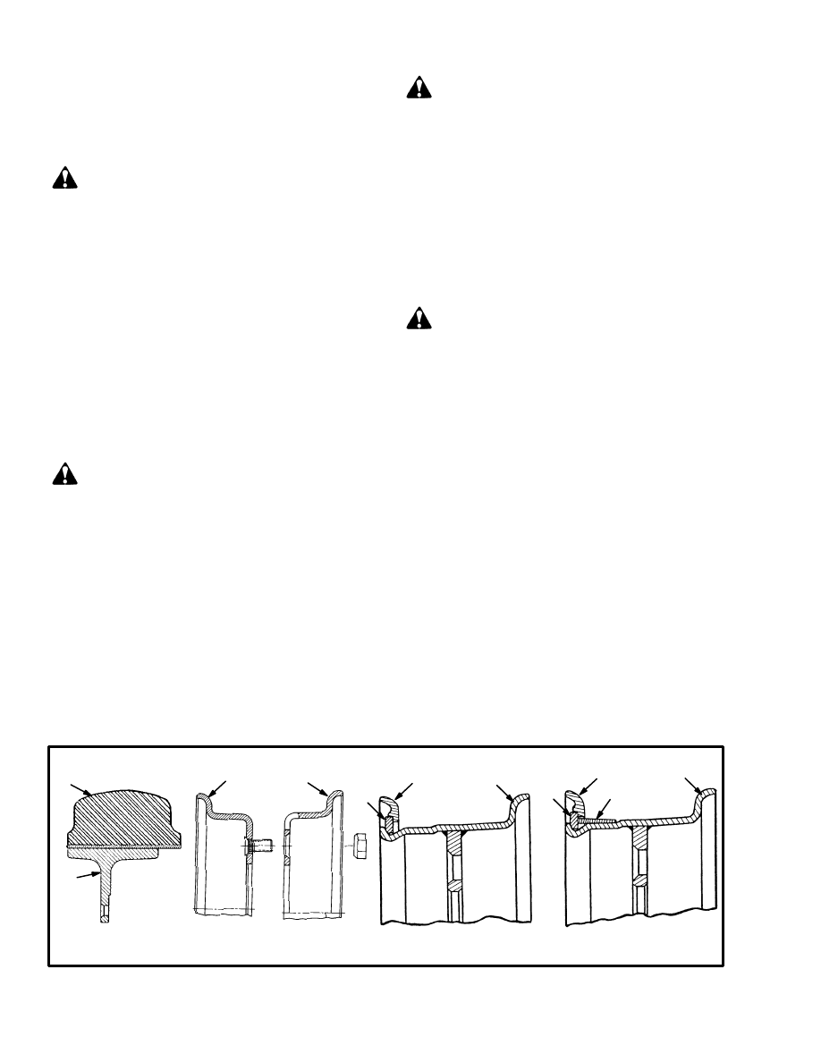
30
WELDING REPAIRS
Some repairs require welding. If an acetylene or arc
welder is used, make sure the procedures in the follow-
ing WARNING and CAUTION are done.
WARNING
Welding can cause a fire or an explosion. Always fol-
low the instructions in the FRAME section of the
SERVICE MANUAL if a fuel or hydraulic tank
must be welded. Make sure there is no fuel, oil, or
grease near the weld area. Make sure there is good
ventilation in the area where the welding must be
done.
Do not heat, weld, or bend forks. Forks are made of
special steel using special methods. Get information
from your dealer for Hyster lift trucks before weld-
ing on an mast.
CAUTION
When an arc welder is used, always disconnect the
battery connector on the lift truck. This action will
prevent damage to the SCR control.
Connect the ground clamp for the arc welder as close
as possible to the weld area. This action will prevent
damage to a bearing from the large current from the
welder.
CHANGES TO THE OVERHEAD GUARD
WARNING
Do not weld mounts for lights or accessories to the
legs of the overhead guard. The strength of the
overhead guard can be reduced by welding or
heating.
WHEELS AND TIRES
WARNING
The type of tire and the tire pressure (pneumatic
tires) are shown on the nameplate. Make sure the
nameplate is correct for the type of tires on the lift
truck.
GENERAL
The E1.25–1.75XL (E25–35XL), E2.00–3.00XL
(E40–60XL) and E3.50–5.50XL (E70–120XL) series
of lift trucks use solid rubber tires. Solid rubber tires
made from softer or harder material can be installed as
optional equipment. The tread on the solid rubber tires
can be either smooth or it can have lugs. DO NOT mix
types of tires or tread on the lift truck.
There are three configurations of drive wheel mounts
used on the E1.25–1.75XL (E25–35XL) series of lift
trucks. See FIGURE 29. The methods used to fasten the
drive wheels to the hub are different for the three con-
figurations. When the drive tires are removed or in-
stalled, small changes in the procedure must be made for
the differences in the axles. DO NOT mix types of tires
or tread on the lift truck.
The J1.25–1.75XL and J2.00–3.00XL (J40–60XL) se-
ries of lift trucks use pneumatic tires or solid rubber tires
that fit on pneumatic type wheels. DO NOT mix types of
tires or tread on the lift truck.
TWO–PIECE WHEEL
THREE–PIECE WHEEL
FOUR–PIECE WHEEL
SOLID RUBBER TIRE AND
WHEEL (PRESS–ON)
9458
11637
4
1. SOLID RUBBER TIRE (PRESS–ON)
2. WHEEL
3. WHEEL RIM
4. SIDE FLANGE
5. LOCK RING
6. FLANGE SEAT
1
2
3
3
4
3
5
6
3
5
FIGURE 27. TYPES OF WHEELS
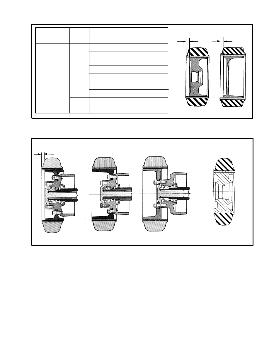
31
UNIT
DRIVE
STEER
127 mm (5 in)
152 mm (6 in)
178 mm (7 in)
203 mm (8 in)
229 mm (9 in)
0
0
0
0
0
178 mm (7 in)
STEER TIRE
AND WHEEL
DRIVE TIRE
AND WHEEL
12188
6.4 mm (0.25 in)
31.8 mm (1.25 in)
TIRE
WIDTH
WHEEL
OFFSET*
MEASUREMENT “A”
25.4 mm (1.0 in)
12.7 mm (0.5 in)
229 mm (9 in)
152 mm (6 in)
STEER
DRIVE
304 mm (12 in)
* OFFSET IS MEASURED AT THE
OUTSIDE OF THE WHEEL.
E40–60XL
E70–120XL
A
A
FIGURE 28. WHEEL AND TIRE MOUNTS, E2.00–3.00XL (E40–60XL)AND E3.50–5.50XL (E70–120XL)
STANDARD
INTERMEDIATE TREAD
WIDE TREAD
19 mm (0.75 in)*
* ON STANDARD DRIVE TIRES ONLY.
MOUNT ALL OTHER DRIVE AND STEER TIRES ALIGNED TO THE OUTSIDE OF THE WHEEL
11456
FIGURE 29. WHEEL MOUNTS, E1.25–1.75XL (E25–35XL)
MOUNT STEER TIRE
ALIGNED TO OUTSIDE
OF THE WHEEL
SOLID RUBBER TIRES (PRESS–ON)
How To Change A Solid Rubber Tire
When new solid rubber tires (press–on) must be in-
stalled, put the lift truck on blocks as described in How
To Put The Lift Truck On Blocks at the beginning of this
section. Remove the wheel. The correct tools, equip-
ment and a press ring must be used for each size wheel.
A press that has a capacity of approximately 36 000 kg
(80 000 lb) is also required to press the wheel from the
rim. Do not try to change the solid rubber tires on the
wheels unless you have the correct tools, equipment and
experience.
Make sure the tires are installed on the wheels to the di-
mensions shown in FIGURE 28. or FIGURE 29. Install
the tires on both drive wheels at the same dimensions.
Install the tires on both steering wheels at the same di-
mensions. Check the nameplate on the lift truck for the
correct tread width. The tread width is measured from
the outside of one wheel to the inside of the other wheel.

32
Install The Wheels
Steering Wheels:
a. Lubricate the bearings with multi–purpose
grease. Install the wheel and bearings on the spin-
dle.
b. Install the washer and nut on the spindle.
c. Tighten the nut to 200 N.m (150 lbf ft) while ro-
tating the wheel. Loosen the nut until the wheel
rotates freely and the bearings are not loose.
Tighten the nut to 35 N.m (25 lbf ft) and install the
cotter pin at the closest slot in the nut.
d. Install the cap for the bearings.
Drive Wheels. Install the wheel on the hub. Tighten the
nuts in a cross pattern to the torque value in the MAIN-
TENANCE SCHEDULE.
WARNING
When the wheels have been installed, check all wheel
nuts after 2 to 5 hours of operation. Tighten the nuts
to the correct torque. When the nuts stay tight for
eight hours, the interval for checking can be ex-
tended to 350 hours.
PNEUMATIC TIRES
WARNING
A solid rubber tire that is the same shape as a pneu-
matic tire can be installed on a wheel for a pneumatic
tire. DO NOT make changes in the parts of the rim if
this type of solid rubber tire is installed instead of a
pneumatic tire.
The type of tire and the air pressure (pneumatic
tires) are shown on the nameplate. Make sure that
the nameplate is correct for the type of tires on the lift
truck.
If a tire has less than 80% of the correct air pressure,
completely remove the air pressure from the tire.
Remove the tire from the lift truck. Add air pressure
to the tire only in a safety cage. See the procedures in
“Add Air To The Tires.”
Remove the Wheels From The Lift Truck
WARNING
Wheels must be changed and tires repaired by
trained personnel only.
Always wear safety glasses.
Completely remove the air from the tire before re-
moving the wheel from the lift truck. Air pressure in
the tires can cause the tire and rim parts to explode
causing serious injury or death.
Never loosen the nuts that hold the inner and outer
wheel halves together when there is air pressure in
the tire.
1. When pneumatic tires must be repaired or new tires
installed, put the lift truck on blocks. See HOW TO PUT
THE LIFT TRUCK ON BLOCKS, page 2.
2. Completely remove the air from the tire. Remove the
valve core to make sure that all of the air is out of the in-
ner tube. Push a wire through the valve stem to make
sure that the stem does not have a restriction.
3. Lift truck tires and wheels are heavy. Remove the
wheel nuts and carefully remove the wheel and tire from
the lift truck.
Remove The Tire From The Wheel
(See FIGURE 30. or FIGURE 31.)
NOTE: When you disassemble the wheels, see
FIGURE 27. There are several types of wheels used on
this series of lift trucks.
WARNING
Make sure all of the air pressure is removed from the
tire before a wheel is disassembled. Air pressure in
the tires can cause the tire and rim parts to explode
causing serious injury or death.
Keep tire tools in firm contact with the wheel parts.
If the tool slips, it can move with enough force to
cause an injury.
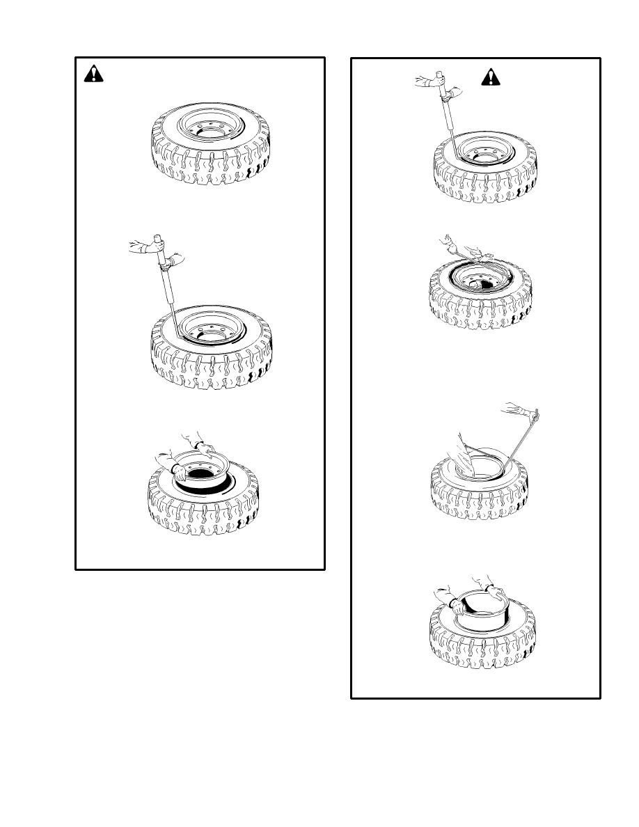
33
STEP 2. Loosen tire bead from wheel rim.
STEP 3. Remove wheel rims from tire.
Remove The inner tube and flap.
SEE WARNINGS
11939
STEP 1. Remove the nuts that fasten the wheel
rims together.
FIGURE 30. TIRE REMOVAL, TWO–PIECE
WHEEL
STEP 1. Loosen the tire bead from the side flange.
STEP 2. Put the tire tool into the slot between the
lock ring and wheel rim. Remove the
lock ring and side flange. If there is a
flange seat, remove it.
STEP 3. Loosen the bead from the other side of
the wheel rim. Remove the valve stem
from the wheel.
STEP 4. Remove the wheel from the tire.
SEE WARNINGS
FIGURE 31. TIRE REMOVAL, THREE AND
FOUR–PIECE WHEELS
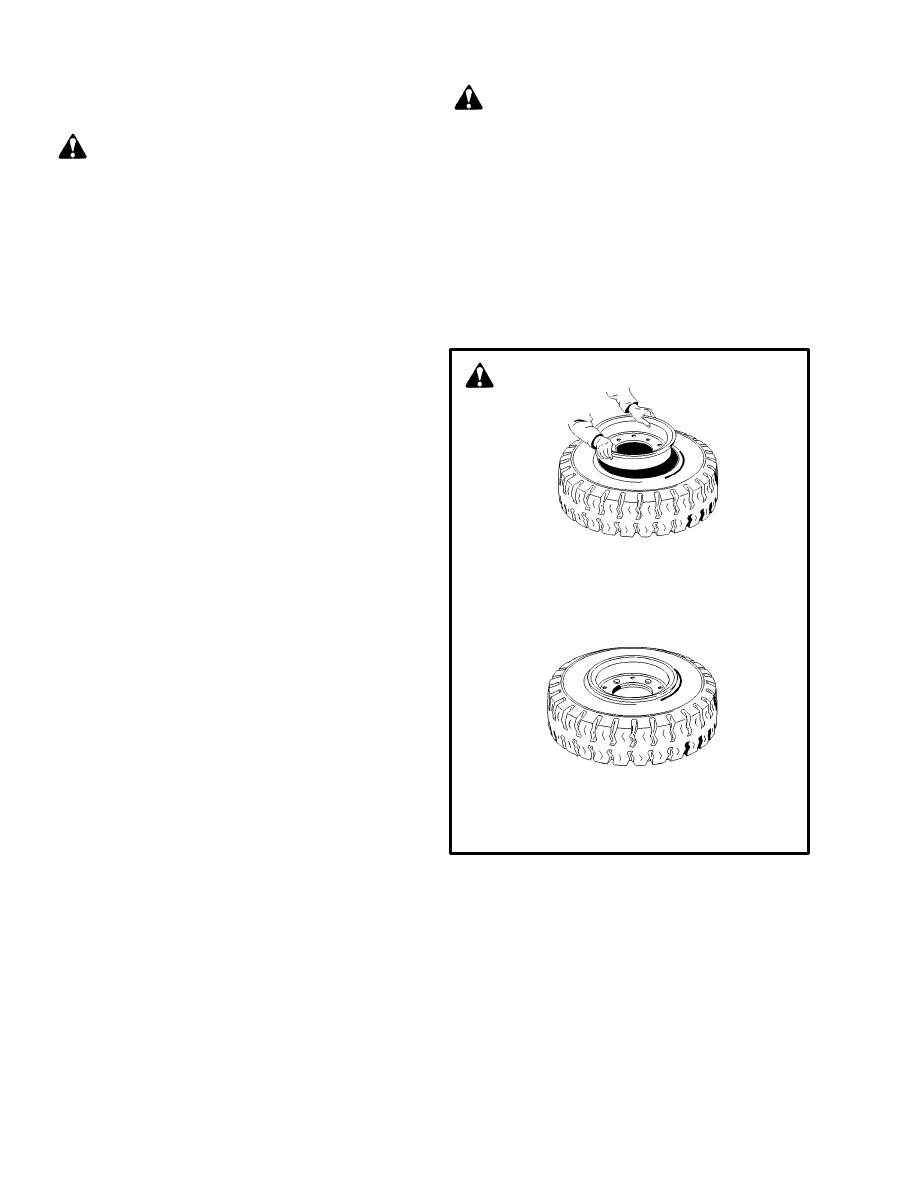
34
Install The Wheel In The Tire
(See FIGURE 32. or FIGURE 33.)
WARNING
Wheels can explode and cause injury or death if the
following procedures are not followed:
•
Clean and inspect all parts of the wheel before
installing the tire.
•
DO NOT use any damaged or repaired wheel
parts.
•
Make sure that all parts of the wheel are the
correct parts for that wheel assembly.
•
DO NOT mix parts between different types or
manufacturers of wheels.
•
DO NOT mix types of tires, type of tire tread,
or wheel assemblies of different manufactur-
ers on any one lift truck.
Do not use a steel hammer on the wheel. Use a rub-
ber, lead, plastic or brass hammer to put parts to-
gether. Make sure that the side flange and lock ring
are in the correct position. The ends of the lock ring
must not touch. The clearance at the ends of the lock
ring must be 2.5 to 6.5 mm (0.10 to 0.25 in) after it is
installed. If the clearance is wrong, the wrong part
has been used.
1. Clean and inspect all parts of the wheel. Paint any
parts that have rust or corrosion.
2. Install a new inner tube in the tire. Used tubes and
flaps can cause tire failure.
3. Apply a rubber lubricant or a soap solution to the tire
bead and tube.
WARNING
Do not lubricate the tire bead with anti–freeze or pe-
troleum based liquid. Vapors from these liquids can
cause an explosion during inflation or use.
4. Install a new tire flap.
5. Make sure the rim is the correct size for the tire. Lubri-
cate the part of the wheel that contacts the bead and flap.
6. Install the two–piece wheel in the tire as shown in
FIGURE 32. Install the three–piece or four–piece wheel
in the tire as shown in FIGURE 33.
11939
STEP 1. Install the inner tube and the rubber flap
in the tire. Install both halves of the
wheel rim in the tire. Make sure the stem
of the inner tube is aligned with the slot
in the rim.
STEP 2. Tighten the nuts that hold the rim halves
together to 175 N.m (130 lbf ft). Add air
pressure to the tire (see the Nameplate).
SEE WARNINGS
FIGURE 32. INSTALL THE WHEEL
IN THE TIRE, TWO–PIECE WHEEL
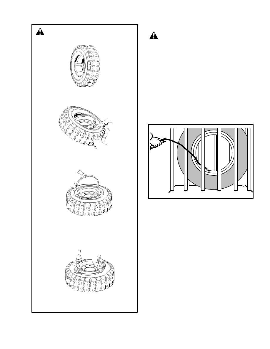
35
STEP 1. Install the inner tube and the rubber flap
in the tire..
STEP 2. Install the wheel rim in the tire. Make
sure the stem of the inner tube is
aligned with the slot in the rim.
STEP 3. Turn over the rim and tire. Put blocks
under the rim so that the rim is 8 to 10
cm (3 to 4 in) above the floor. Install the
flange seat (if used) and the lock ring.
STEP4. Put the lock ring in the correct position
on the rim. Add air pressure to the tire as
described in “Add Air To The Tires”.
SEE WARNINGS
FIGURE 33. INSTALL THE WHEEL IN THE
TIRE, THREE OR FOUR–PIECE WHEEL
Add Air To The Tires (See FIGURE 34.)
WARNING
Add air pressure to the tires only in a safety cage. In-
spect the safety cage for damage before use. When
air pressure is added, use a chuck that fastens onto
the valve stem of the inner tube. Make sure there is
enough hose to permit the operator to stand away
from the safety cage when air pressure is added to the
tire.
Do not sit or stand by the safety cage. Do not use a
hammer to try and correct the position of the side
flange or lock ring when the tire has air pressure
greater than 20 kPa (3 psi).
FIGURE 34. ADD AIR TO THE TIRES
1. Put the tire in a safety cage.
2. Add 20 kPa (3 psi) of air pressure to the tire.
3. Check that all wheel parts are correctly installed. Tap
the lock ring with a soft hammer to make sure that the
lock ring is in the seat.
4. If installation is correct, add air pressure to the tire to
the specified pressure.
5. Check that all wheel parts are correctly installed. If in-
stallation is not correct, remove all of the air pressure
from the tire. Remove the valve core to make sure all of
the air pressure has been removed and then make adjust-
ments. The clearance at the ends of the lock ring will be
2 to 6 mm (0.10 to 0.25 in) when the tire has the correct
air pressure.
Install The Wheels
Install the wheel on the hub. Tighten the nuts as shown
in the MAINTENANCE SCHEDULE. If the wheels are
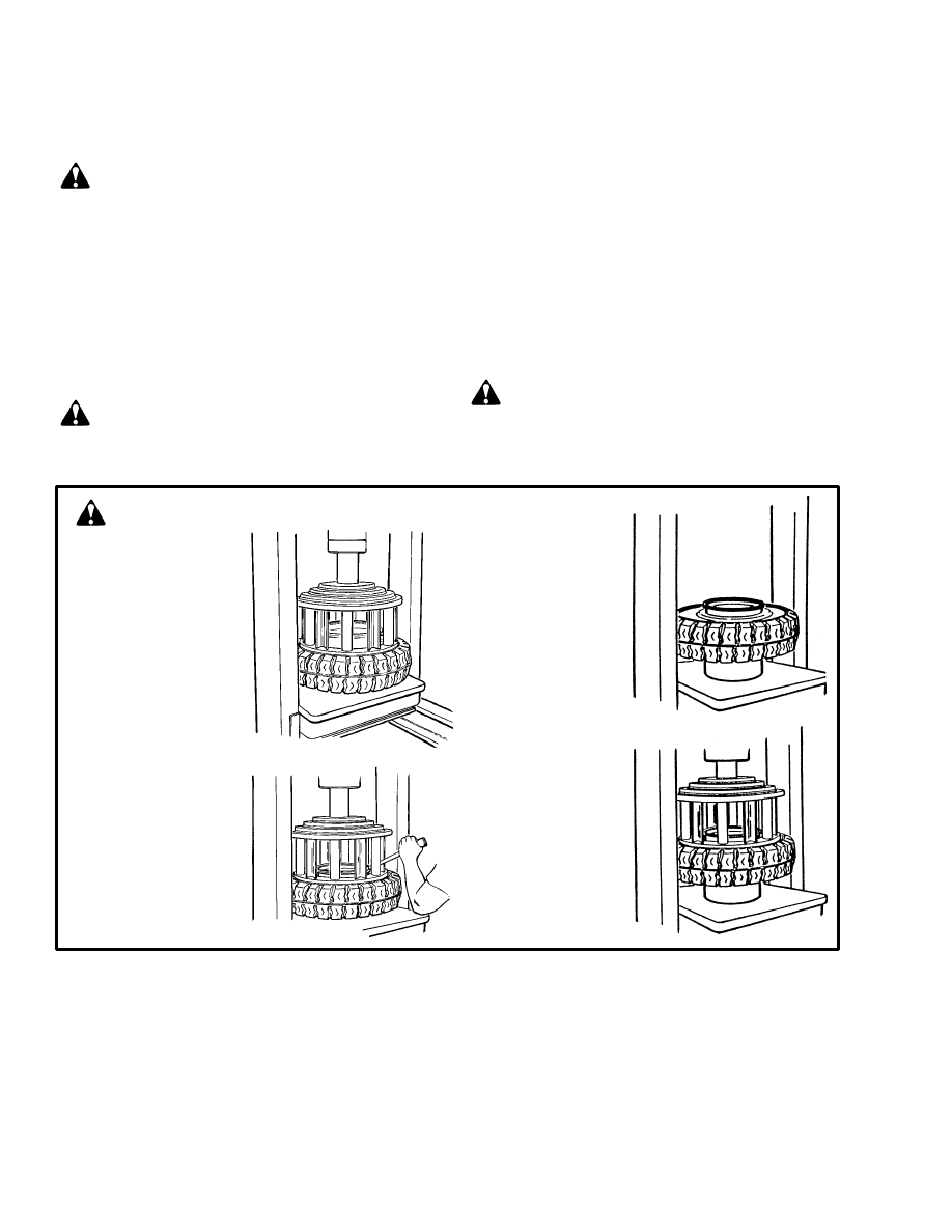
36
the two–piece rims, make sure the nuts that fasten the
rim halves together are toward the hub when they are in-
stalled.
WARNING
When the wheels have been installed, check all wheel
nuts after 2 to 5 hours of operation. Tighten the nuts
to the correct torque. When the nuts stay tight for
eight hours, the interval for checking can be ex-
tended to 350 hours.
SOLID RUBBER TIRES THAT
LOOK LIKE PNEUMATIC TIRES
WARNING
Wheels must be changed and tires repaired by
trained personnel only.
Always wear safety glasses.
1. Put the lift truck on blocks as described in “How To
Put The Lift Truck On Blocks” at the beginning of this
section.
2. Remove the wheel nuts and remove the wheel and tire
from the lift truck. Lift truck tires and wheels are heavy.
Remove The Tire From The Wheel
(See FIGURE 35.)
NOTE: When you disassemble the wheels, see
FIGURE 27. There are several types of wheels used on
these series of lift trucks.
WARNING
Keep tire tools in firm contact with the wheel. If the
tool slips, it can move with enough force to cause seri-
ous injury.
FIGURE 35. REMOVE THE TIRE FROM THE WHEEL
STEP 2. Put the tire
tool into the
slot between
the lock ring
and the wheel
rim. Remove
the lock ring
and side
flange.
STEP1. Put the wheel
rim on the bed
of the press.
Put the cage
in position on
the tire. Use
the press to
push the tire
away from the
side flange.
STEP 3. Turn the tire
over. Put a
support under
the wheel rim.
Make sure
the wheel rim
is at least 150
to 200 mm (6
to 8 inches)
from the bed
of the press.
STEP 4. Put the cage
in position on
the tire. Use
the press to
push the tire
from the
wheel rim.
SEE WARNINGS
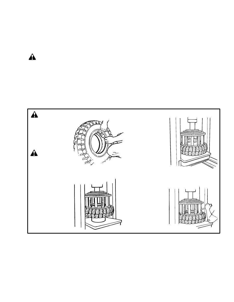
37
Install The Tire On The Wheel
(See FIGURE 36.)
NOTE: When you assemble the wheels, see
FIGURE 27. There are several types of wheels used on
these series of lift trucks.
WARNING
Failure to follow these procedures will cause damage
to the tire and wheel assembly and can cause an
injury.
•
Clean and inspect all parts of the wheel before
installing the tire.
•
DO NOT use any damaged or repaired wheel
parts.
•
Make sure that all parts of the wheel are the
correct parts for that wheel assembly.
•
DO NOT mix parts between different types or
manufacturers of wheels.
•
DO NOT mix types of tires, type of tire tread, or
wheel assemblies of different manufacturers
on any one lift truck.
Do not use a steel hammer on the wheel. Use a rub-
ber, lead, plastic or brass hammer to put parts to-
gether. Make sure that the side ring is in the correct
position. The ends of the side ring must not touch.
The clearance at the ends of the lock ring will be
approximately 13 to 25 mm (0.5 to 1.0 in) after it is
installed. If the clearance is wrong, the wrong part
has been used.
STEP 4. While the cage
is holding the
tire on the wheel
rim, install the
lock ring. Use a
tire tool to make
sure the lock
ring is in the cor-
rect position.
FIGURE 36. INSTALL THE TIRE ON THE WHEEL
STEP 1. Lubricate the
wheel rim and
the inner sur-
face of the tire
with tire lubri-
cant or soap.
12602
STEP 2. Put the wheel
rim on the bed
of the press.
Put the tire
over the wheel
rim. Put the
cage in position
on the tire. Use
the press to in-
stall the tire on
the wheel rim.
CAUTION
Too much lubricant can
cause the tire to slide and
move around the wheel rim.
STEP 3. Remove the cage
and put the flange
seat (if used),the
side ring and the
lock ring in posi-
tion on the wheel
rim. Install the
cage on the tire.
Use the press to
push the tire onto
the wheel rim so
that the side flange
and lock ring can
be installed.
SEE WARNINGS

38
E/J1.25–1.75XL (E25–35XL)
Wheel nut torque, drive wheels
155 N.m (115 lbf ft)
Drive tires, size:
E1.25XL (E25XL) (solid rubber)
18 x 5 x 12.12
J1.25XL (E25XL) (pneumatic)
18 x 7 – 8 (16 ply) 1 MPa (145 psi)
E1.50–1.75XL (E30–35XL) (solid rubber)
18 x 6 x 12.12
J1.50–1.75XL (E30–35XL) (pneumatic)
18 x 7 – 8 (16 ply) 1 MPa (145 psi)
Steering tires, size:
E1.25–1.75XL (E25–35XL) (solid rubber)
14 x 4.5 x 8
J1.25–1.75XL (E25–35XL) (pneumatic)
15 x 4.5 – 8 (12 ply) 1 MPa (145 psi)
Wheel nut torque (pneumatic tires, steering)
155 N.m (115 lbf ft)
E2.00–3.00XL (E40–60XL)
Wheel nut torque, drive wheels
235–305 N.m (175–225 lbf ft)
Drive tires, size:
E2.00XL (E40XL) (solid rubber)
18 x 7 x 12.12
E2.50XL (E50XL) (solid rubber)
18 x 8 x 12.12
E3.00XL (E60XL) (solid rubber)
18 x 9 x 12.12
Steering tires, size:
E2.00XL (E40XL) (solid rubber)
16 x 5 x 10.5
E2.50–3.00XL (E50–60XL) (solid rubber)
16 x 6 x 10.5
E3.5–5.50XL (E70–120XL)
Wheel nut torque, drive wheels
600 N.m (443 lbf ft)
Drive tires, size:
E3.50–4.00XL (E70–80XL) (solid rubber)
22 x 9 x 16
E4.50–5.50XL (E100–120XL) (solid rubber)
22 x 12 x 16
Steering tires, size:
E3.50–4.00XL (E70–80XL) (solid rubber)
18 x 6 x 12.12
E4.50–5.50XL (E100–120XL) (solid rubber)
18 x 7 x 12.12
J2.00–3.00XL (J40–60XL)
Wheel nut torque, drive wheels
235–305 N.m (175–225 lbf ft)
Wheel nut torque, steering wheels
155 N.m (115 lbf ft)
Drive tires, size (pneumatic)
23 x 10 – 12 (16 ply) 930 kPa (135 psi)
Steering tires, size (pneumatic)
18 x 7 – 8 (16 ply) 1 MPa (145 psi)
SPECIFICATIONS
39
REFERENCE TABLE
Hyster
Loctite
Part No.
Part No.
Description
Size
360387
222
Small Screw Threadlock (Purple)
50 ml
318702 *
242
Removable Threadlock (Blue)
10 ml
226414 *
271
High Strength Threadlock (Red)
10 ml
318996
277
High Viscosity Threadlock (Red)
50 ml
318650
290
Low Viscosity Threadlock (Green)
0.02 oz
251099
290
Low Viscosity Threadlock (Green)
50 ml
355844 *
422
SuperBonderR Adhesive
3 ml
350830
515
Gasket Eliminator (Purple)
6 ml
313022 *
515
Gasket Eliminator (Purple)
50 ml
273338 *
567
Pipe Sealant with TeflonR (White)
50 ml
318705
595
Super FlexR Silicone
100 ml
318701 *
609
Retaining Compound
10 ml
341959
680
Retaining Compound
50 ml
226415
Primer T – Aerosol
6 oz
316865
Anti–Seize Compound
1 lb
360053–10
Chisel Gasket Remover (10 Aerosol cans per case)
18 oz
318700 *
Adhesive & Sealant Kit [Contains one each of * items]
Hyster
Description
Size
Part No.
336830
Hydraulic and Tractor Transmission Oil (J20A Specifications)
1 qt
336831
Hydraulic and Tractor Transmission Oil (J20A Specifications)
2 gallon
336832
Hydraulic and Tractor Transmission Oil (J20A Specifications)
5 gallon
336833
Hydraulic and Tractor Transmission Oil (J20A Specifications)
55 gallon
3002338
Anti–Freeze (Ethylene Glycol)
1 gallon
326457
Multi–Purpose Grease
5 lb
328388
Spray–Lubricant, Silicone
8 & 16 oz
Adhesives And Sealants
Hydraulic Oil, Lubricant, And Coolant Specifications
Loctite
, Super Flex
, and SuperBonder
are registered
trademarks of the Loctite Corporation.
Teflon
is a registered trademark of Du Pont de Nemours Co. Inc.
Document Outline
- INTRODUCTION
- MAINTENANCE SCHEDULE
- MAINTENANCE PROCEDURES EVERY 8 HOURS OR DAILY
- EVERY 350 HOURS OR TWO MONTHS
- HYDRAULIC TANK BREATHER
- STEERING TIE RODS, E/J 1.25-1.75XL (E25-35XL) and J2.00-3.00XL (J40-60XL)
- DIFFERENTIAL AND SPEED REDUCER
- WHEEL NUT TORQUES
- STEERING AXLE SPINDLES, E/J2.00-3.00XL (E/J40-60XL) E3.50-5.50XL (E70-120XL)
- MAST
- LIFT CHAINS
- FORKS
- BRAKE FLUID
- OTHER LUBRICATION
- SEAT BRAKE
- ELECTRICAL INSPECTION
- EVERY 2000 HOURS OR YEARLY
- GENERAL PROCEDURES
- WHEELS AND TIRES
- SPECIFICATIONS
- REFERENCE TABLE
Wyszukiwarka
Podobne podstrony:
1452930 8000SRM0680 (12 2002) UK EN
1483865 8000SRM0916 (12 2003) UK EN
910442 8000SRM0231 (12 2004) UK EN
1510478 8000SRM0988 (06 2005) UK EN
1554635 8000SRM1079 (06 2004) UK EN
1565454 8000SRM1113 (06 2004) UK EN
897457 8000SRM0488 (03 1992) UK EN
1494145 8000SRM0940 (10 2003) UK EN
1526432 8000SRM1041 (07 2002) UK EN
1554636 8000SRM1080 (11 2004) UK EN
1566279 8000SRM1155 (02 2005) UK EN
1466211 2000SRM0754 (12 2003) UK EN
1494141 1800SRM0937 (12 2003) UK EN
897125 1300SRM0344 (07 1993) UK EN
więcej podobnych podstron