voltage on to C1, which charges up to a voltage, deter-
mined by the voltage divider R1/R2, that is 0.3 V higher than
the output voltage. The small charging peaks shown in
curve 2 are not drawn to scale. If V
LX
is more than 0.7 V
lower than V
C1
, transistor T conducts and passes the volt-
age across C1 on to C2. The small voltage sags shown in
curve 3 are also not drawn to scale, for the sake of clarity.
If the step-up regulator IC is disabled, the voltage across
C1 will be only as high as the input voltage. This voltage is
also present at LX, so there is not enough base bias volt-
age to switch on the transistor, and it is cut off.
(014080-1)
SUMMER CIRCUITSCOLLECTION
78
Elektor Electronics
7-8/2001
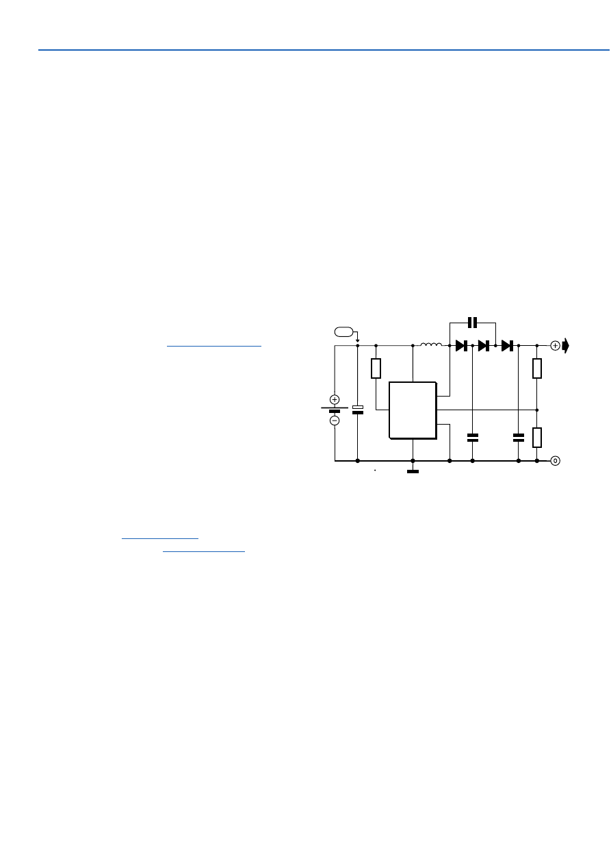
The circuit shows one way of obtaining a voltage of 90 V
from a 1.5 V battery supply. The LT1073 switching regula-
tor from Linear Technology (
www.linear-tech.com
) oper-
ates in boost mode and can work with an input voltage as
low as 1.0 V. The switching transistor, which is hidden
behind connections SW1 and SW2, briefly takes one end of
choke L1 to ground. A magnetic field builds up in the
choke, which collapses when the transistor stops conduct-
ing: this produces a current in diode D1 which charges C3.
The diode cascade comprising D1, D2, D3, C2, C3 and C4
multiplies the output voltage of the regulator by four, the
pumping of C2 causing the voltage developed across C4
via C3, D2 and D3 to rise. Finally, the regulator control loop
is closed via the potential divider (10 M
Ω
and 24 k
Ω
).
These resistors should be 1 % tolerance metal film types.
With the given component values, fast diodes with a
reverse voltage of 200 V (for example type MUR120 from
On Semiconductor
www.onsemi.com
) and a choke such as
the Coilcraft DO1608C-154 (
www.coilcraft.com
) an output
voltage of 90 V will be obtained. The output of the circuit
can deliver a few milliamps of current.
(014113-1)
043
LT1073
IC1
VIN
GND
SW1
SW2
IL
FB
5
2
3
1
8
4
R1
220
Ω
R2
10M
1%
R3
24k
1%
C1
10µ
C4
470n 100V
C2
470n
100V
BT1
1V5
L1
150µH
D1
D2
D3
C3
470n 100V
+90V
D1...D3 = MUR120
*
014113 - 11
1V5
zie tekst
*
see text
*
siehe Text
*
voir texte
*
10V
High Voltage Converter:
90 V from 1.5 V
In the December issue we’ll describe a fancy Li-Ion
charger based on a specially designed IC and boasting
many bells and whistles. However, it can also be done in a
much simpler way, provided you are prepared to work
carefully. The latter is particularly important, because we
will point out again that charging Li-ion batteries with a
voltage that is too high can cause explosions! In this
respect Li-ion batteries are not the least comparable with
the much less critical NiCd- or NiMH-types.
Li-ion batteries may, just like lead-acid batteries, be
charged with a constant voltage. The charging voltage for a
3.6 V cell is 4.1 V maximum, and for 3.7 V cells this is 4.2 V.
Higher voltages are not permissible; lower voltages are,
but every 0.1 V results in a reduction of capacity of about
7%. As a consequence, great precision is required and it is
therefore highly recommended to measure the output volt-
age with an accurate (less than 1% error) digital voltmeter.
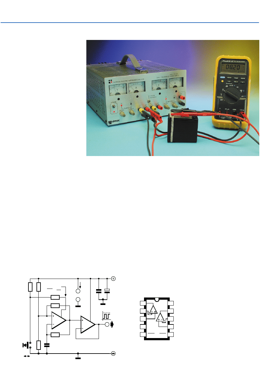
A good stabilised lab power supply is in principle perfectly
suited as a Li-Ion charger. Adjust it to 4.1 V (or 8.2 V if you
are charging two cells in series) and also adjust the current
limiting to an appropriate value, 1 C for example (where C
is the capacity, e.g.,. 1 A for a 1 Ah battery). A too low value
044
Lithium-Ion Charger II
is preferred over one that is too
high; when the value is a little
low it will simply take a little
longer to fully charge the battery,
but it makes no difference other-
wise. Li-Ion batteries are not
suitable for high currents, so lim-
iting the value to 1C is a safe
maximum.
You can now connect the bat-
tery. If the battery is discharged,
the power supply will deliver the
maximum adjusted current at a
voltage less than 4.1 V. As the
battery is charging, the voltage
will rise. Once the value of 4.1 V
is reached, the voltage will
cease to rise and the current will
begin to fall. When the current is
less that 0.2 of the adjusted
value, the battery can be consid-
ered charged. It is not a disaster if the battery is connected
for longer; overcharging is not possible provided the volt-
age is less than 4.1 V per cell.
Keep children, cleaning housewives, pets and other pos-
sible disturbances away to avoid an inadvertent change of
the voltage knob. It may not be a silly idea to provide the
adjustment knob of the power supply with some method of
mechanical locking.
Note. Although they can hardly be called new, Li-Ion
batteries are still difficult to obtain as spare parts. It may be
a useful hint to also look at replacement batteries for cam-
corders and laptops as in these applications Li-Ion batter-
ies are very common.
(014133-1)
SUMMER CIRCUITSCOLLECTION
79
7-8/2001
Elektor Electronics
K. Thiesler
The new range of low-noise, high-
speed and low-distortion BiMOS op-
amps from Texas Instruments, type
TLC070 to TLC075, is intended for
use in instrumentation, audio and
automotive applications. This oscil-
lator is an ideal example of its appli-
cation: a stable, highly accurate
squarewave at frequencies up to
60 kHz can be produced with an out-
put current of
±
30 mA.
The TLC073, a dual op-amp with
shutdown function, is used here.
IC1a is configured as a standard
squarewave generator, IC1b as a dri-
ver. The frequency of oscillation
depends on Cx and Rx and is calcu-
045
R3
22k
R
100k
R5
22k
R4
22k
R1
22k
R2
22k
IC1.A
2
3
1
5
IC1.B
8
7
9
6
C
100p
S1
IC1
10
4
C2
22µ
35V
C1
47n
OSC
ON
OFF
V
DD
+4V5...16V
X
X
3mA8
014014 - 11
SHDN
Shutdown mode:
V
<
V
DD
2
VDD - 1V0 (30mA)
+0V4 (- 30mA)
IC1 = TLC073
TLC073
SHDN
SHDN
GND
DD
10
1
2
3
4
A
B
V
5
6
7
8
9
Squarewave Oscillator
Using TLC073
Wyszukiwarka
Podobne podstrony:
e017042
e017040
e017048
e017049
e017043
e017047
e017046
e017041
e017045
e017042
e017047
e017043
e017049
więcej podobnych podstron