supply voltage. A voltage of around +9 V is thus available
from C4, which is connected to the collector of optocoupler
IC3. In principle, the voltage level at an RS232 interface
should be +12 V to +15 V, but PCs can generally work with
significantly lower voltages. Notebook computers in partic-
ular sometimes have a voltage of only +8 V.
The emitter of IC3 leads to the RxD input of the RS232 port
and is held at around –9 V by R3. When the microcontroller
transmits data, the pulses from the TxD output of the micro-
controller arrive at the LED of optocoupler IC3. The tran-
sistor of IC3 switched on and applies the positive voltage
to the RxD input of the external device.
Normal diodes (1N4148) can also be used in place of the
Schottky diodes, although the generated voltages will be
somewhat lower. The 6N136 optocoupler is a high-speed
type; normal optocouplers are not suitable. The circuit can
theoretically transmit data at up to 57,600 baud, but in prac-
tice microcontroller circuits only use 9600 baud. These data
transmission rates have been successfully used with both
older-model and more recent notebook computers.
(000082-1)
SUMMER CIRCUITSCOLLECTION
77
7-8/2001
Elektor Electronics
Nowadays, there is a whole series of switching regulator ICs
that work according to the step-up principle and thus con-
vert the input voltage to a higher output voltage. This takes
place using coil L, which is periodically switched to ground
via the LX connection of the IC. This causes a magnetic field
to build up in the coil L, and this field stores energy. When
the step-up regulator IC switches off, the collapsing mag-
netic field in L forces the current to continue to flow. Now,
however, the current must flow through diode D to the out-
put capacitor and the external load connected to Vout. In this
way, a voltage is generated that is greater than the input volt-
age. Resistors R1 and R2 form a voltage divider that is used
to set the value of the output voltage, according to the for-
mula shown. The value of V
ref
is usually around 1.2 V.
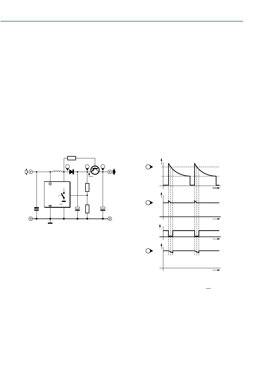
One problem with the step-up regulator is that if the IC is
inactive, there is always a current path from the input to the
output via coil L and diode D. This means that the output volt-
age is not zero, but instead Vin. This problem can be elimi-
nated with the aid of a simple transistor and a series base
resistor. The pnp transistor, in this case a BCP69, is placed in
042
L
D
C1
100µ
C2
100µ
R2
R1
T
100k
1
2
3
014080 - 11
U
IN
U
OUT
U
OUT
+ 0V3
Switcher IC
Step-Up
ON/OFF
IC1
FB
LX
t
U
LX
t
U
C1
t
U
C2
t
T
U
IN
U
OUT
U
OUT
+ 0V3
ON
OFF
1
2
3
014080 - 12
Output Cutoff for
Step-Up Switching Regulator
series with the output circuit and periodically passes the dc
output voltage of the switching regulator to output capacitor
C2. The base of transistor T is connected via the series resis-
tor R to the switch pin LX of the step-up regulator IC.
The voltage waveforms are shown in the diagram. Pin LX
is periodically switched to ground. As soon as the switch
goes open, a voltage pulse that adds to the input voltage
appears at LX. Diode D conducts briefly and passes this
V
V
V
out
ref
R
R
+
=
⋅ +
0 3
1
1
2
,
voltage on to C1, which charges up to a voltage, deter-
mined by the voltage divider R1/R2, that is 0.3 V higher than
the output voltage. The small charging peaks shown in
curve 2 are not drawn to scale. If V
LX
is more than 0.7 V
lower than V
C1
, transistor T conducts and passes the volt-
age across C1 on to C2. The small voltage sags shown in
curve 3 are also not drawn to scale, for the sake of clarity.
If the step-up regulator IC is disabled, the voltage across
C1 will be only as high as the input voltage. This voltage is
also present at LX, so there is not enough base bias volt-
age to switch on the transistor, and it is cut off.
(014080-1)
SUMMER CIRCUITSCOLLECTION
78
Elektor Electronics
7-8/2001
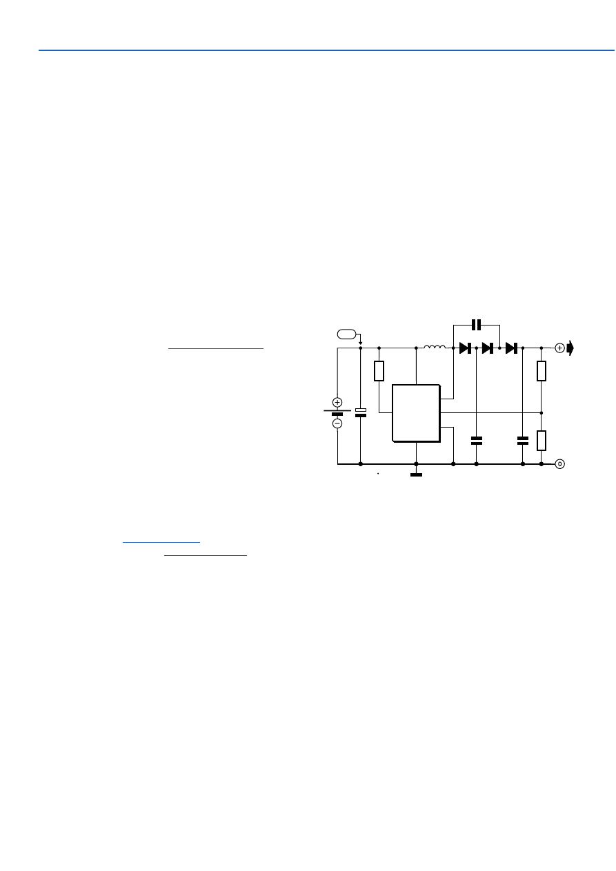
The circuit shows one way of obtaining a voltage of 90 V
from a 1.5 V battery supply. The LT1073 switching regula-
tor from Linear Technology (
www.linear-tech.com
) oper-
ates in boost mode and can work with an input voltage as
low as 1.0 V. The switching transistor, which is hidden
behind connections SW1 and SW2, briefly takes one end of
choke L1 to ground. A magnetic field builds up in the
choke, which collapses when the transistor stops conduct-
ing: this produces a current in diode D1 which charges C3.
The diode cascade comprising D1, D2, D3, C2, C3 and C4
multiplies the output voltage of the regulator by four, the
pumping of C2 causing the voltage developed across C4
via C3, D2 and D3 to rise. Finally, the regulator control loop
is closed via the potential divider (10 M
Ω
and 24 k
Ω
).
These resistors should be 1 % tolerance metal film types.
With the given component values, fast diodes with a
reverse voltage of 200 V (for example type MUR120 from
On Semiconductor
www.onsemi.com
) and a choke such as
the Coilcraft DO1608C-154 (
www.coilcraft.com
) an output
voltage of 90 V will be obtained. The output of the circuit
can deliver a few milliamps of current.
(014113-1)
043
LT1073
IC1
VIN
GND
SW1
SW2
IL
FB
5
2
3
1
8
4
R1
220
Ω
R2
10M
1%
R3
24k
1%
C1
10µ
C4
470n 100V
C2
470n
100V
BT1
1V5
L1
150µH
D1
D2
D3
C3
470n 100V
+90V
D1...D3 = MUR120
*
014113 - 11
1V5
zie tekst
*
see text
*
siehe Text
*
voir texte
*
10V
High Voltage Converter:
90 V from 1.5 V
In the December issue we’ll describe a fancy Li-Ion
charger based on a specially designed IC and boasting
many bells and whistles. However, it can also be done in a
much simpler way, provided you are prepared to work
carefully. The latter is particularly important, because we
will point out again that charging Li-ion batteries with a
voltage that is too high can cause explosions! In this
respect Li-ion batteries are not the least comparable with
the much less critical NiCd- or NiMH-types.
Li-ion batteries may, just like lead-acid batteries, be
charged with a constant voltage. The charging voltage for a
3.6 V cell is 4.1 V maximum, and for 3.7 V cells this is 4.2 V.
Higher voltages are not permissible; lower voltages are,
but every 0.1 V results in a reduction of capacity of about
7%. As a consequence, great precision is required and it is
therefore highly recommended to measure the output volt-
age with an accurate (less than 1% error) digital voltmeter.
A good stabilised lab power supply is in principle perfectly
suited as a Li-Ion charger. Adjust it to 4.1 V (or 8.2 V if you
are charging two cells in series) and also adjust the current
limiting to an appropriate value, 1 C for example (where C
is the capacity, e.g.,. 1 A for a 1 Ah battery). A too low value
044
Lithium-Ion Charger II
Wyszukiwarka
Podobne podstrony:
e017040
e017048
e017049
e017043
e017047
e017046
e017041
e017044
e017045
e017047
e017043
e017049
więcej podobnych podstron