were fitted with a switched mains output socket for the
monitor. The main power switch on the PC controlled this
socket, therefore: computer off = monitor off!
Modern PCs make use of a ‘soft’ power switch, which
puts the power supply in standby mode only; as a conse-
quence the switched mains output on the back of the power
supply is usually omitted. Progress therefore, compels the
user once again, to separately switch off the monitor by
hand. Naturally, this is often forgotten.
Fortunately, there is an easy way to do something about
this. It so happens that when the PC is switched on, a
potential of +5 V is present at the game port. Therefore, it
is enough to simply tie a relay to this signal, which then
switches the monitor (and printer, etc.). This uncompli-
cated relay circuit restores an old convention: computer off
= monitor off!
(014004-1)
SUMMER CIRCUITSCOLLECTION
81
7-8/2001
Elektor Electronics
Rev. T. Scarborough
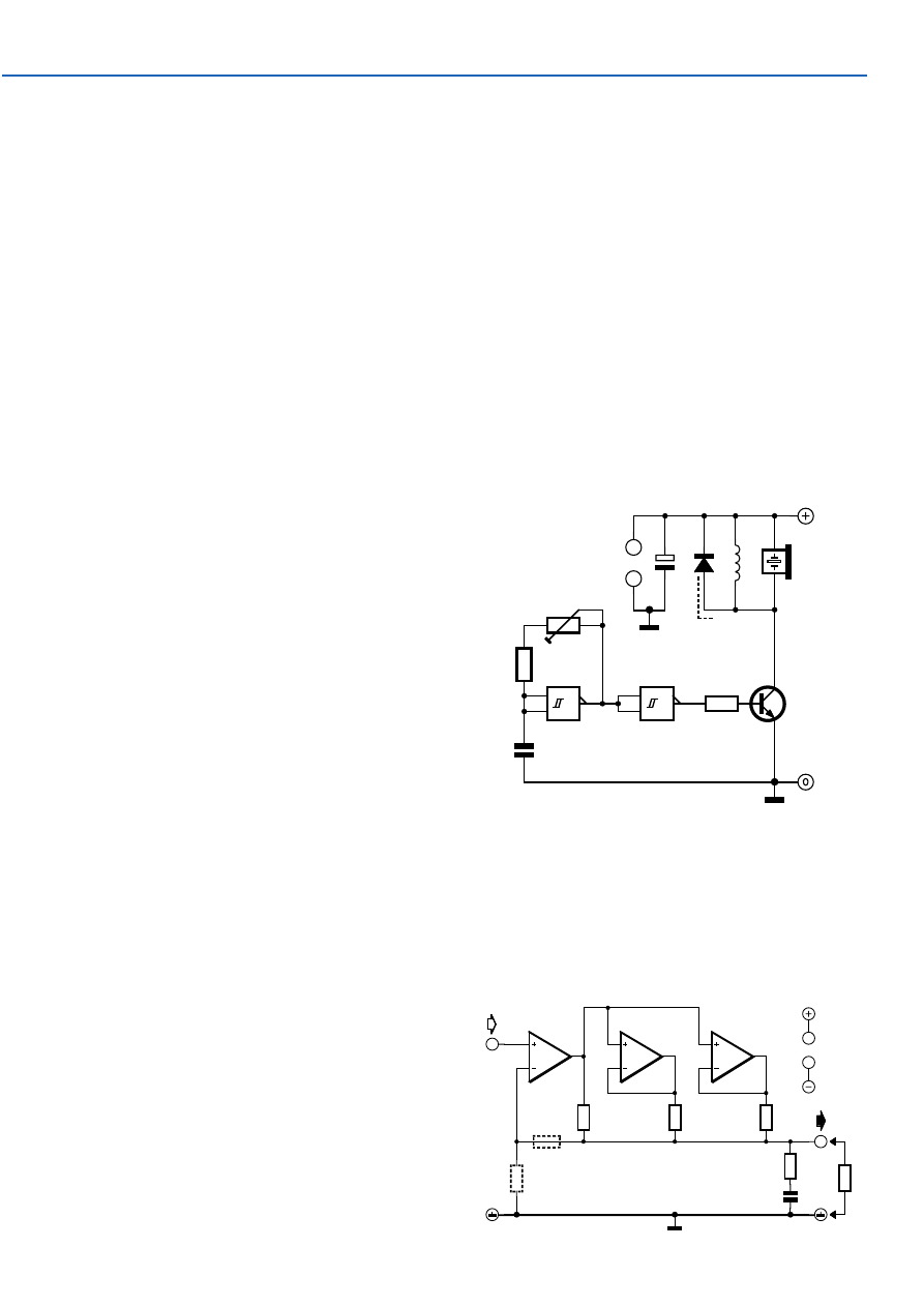
This circuit takes advantage of back-e.m.f. (electromotive
force) to amplify the voltage across a piezo sounder. Ordi-
narily, IC1 would only achieve a gentle beep. However, the
addition of a very high inductance choke of a few Henry —
in this case the coil of a miniature reed relay is used —
achieves a penetrating screech, and represents an easy
method of obtaining considerably more volume in such a
circuit.
The usual protective diode (D1) may be included across
the choke, at the expense of a little volume. In practice, it
was found that no harm was done by omitting D1. The oper-
ating voltage of the relay is immaterial, as long as it is not
less than the supply voltage. Preset P1 should be adjusted
to find the piezo sounder’s resonant frequency. A higher
supply voltage means greater volume — as long as T1’s
ratings are not exceeded.
(010069-1)
047
1
2
3
IC1.A
&
5
6
4
IC1.B
&
100k
P1
R1
10k
C2
47n
R2
10k
T1
BC337
BZ1
D1
1N4001
RLA
+3V...+18V
C1
100µ
25V
IC1
14
7
IC1 = MC14093BCP
010069 - 11
Piezo Amp
National Semiconductor application note
Some applications notes are real evergreens. This one
originally dates from 1979(!) but has lost nothing of its rel-
evance and is always very interesting when you’re looking
for something like this.
Opamps can only deliver a limited current; typically only
about 10 mA max. When more current is required, several
opamps can be connected in parallel. But this usually does-
n’t work very well because opamps are never 100% equal.
In practice they will fight each other and only get warm,
which was not the intention of course.
048
2
3
1
IC1.A
6
5
7
IC1.B
9
10
8
IC1.C
R1
47
Ω
R4
47
Ω
R5
47
Ω
R6
15
Ω
R
R2
R3
C1
47n
IC1
11
4
+Ub
–Ub
014065 - 11
L
IC1 = LM324
Parallel Opamps
Wyszukiwarka
Podobne podstrony:
e017042
e017040
e017048
e017049
e017043
e017047
e017046
e017041
e017044
e017045
e017042
e017043
e017049
więcej podobnych podstron