lated (for frequencies up to 20 kHz) as follows:
where Rx is measured in Ohms and Cx in Farads.
The table shows preferred values that give various fre-
quencies. Note that the frequency variation is largely deter-
mined by the capacitor, since Rx must always be signifi-
cantly larger than feedback resistor R3. The effect of sup-
ply voltage, at –130 dB, is negligibly small, and the
temperature coefficient of frequency is very low: only 1.5 %.
At frequencies above 20 kHz the oscillator remains stable,
but increasingly non-linear.
The mark-space ratio of the signal can be adjusted in the
range 10% to 90% by changing the ratio of resistors R1 to
R2. If the two resistors are equal, the output is symmetrical.
The output of the driver swings between +0.3 V (low) and
1 V below the supply voltage (high).
The oscillator is switched on and off via the shutdown
input of IC1a. The output of the opamp goes to high imped-
ance and the current consumption drops to 35 nA.
The oscillator can of course be built using the common or
garden TL071 (U
b
=7 V, U
out
=1.2/6.2 V, I
out
=1.75 mA,
f
max
=50 kHz). As can be seen, the output drive capability
f
Rx Cx
Rx Cx
=
×
×
+
×
×
1
2
1
7000
3
is rather lower.
(014014-1)
f
60 kHz
10 kHz
6 kHz
3 kHz
400 Hz
50 Hz
Cx
100 pF
680 pF
1 nF
1 nF
10 nF
68 nF
Rx
100 k
Ω
100 k
Ω
100 k
Ω
220 k
Ω
180 k
Ω
220 k
Ω
SUMMER CIRCUITSCOLLECTION
80
Elektor Electronics
7-8/2001
BiMOS opamp family TLC07x
The new family of BiMOS opamps types TLC070 to TLC075
replaces the older TL070 family of BiFET amplifiers. The new
components incorporate some significant advances:
– Very low noise (7 nV/
√
Hz)
– Low harmonic and non-harmonic distortion (0.002 %)
at A = 1
– Bandwidth 10 MHz, slew rate 16 V/µs
– Input quiescent current only 1.5 pA
– Offset voltage 60 µV
– Output current
±
50 mA
– Supply voltage rejection –130 dB
– Quiescent current consumption 1.9 mA per opamp
– Symmetric (
±
2.25 to 8 V) or single supply voltage
(+4.5 to16 V)
– Shutdown function for each opamp (TLC070, TLC073 and
TLC075 only)
– Single, dual and quad opamps available in DIP, SO
and TSSOP packages
P. van Geens
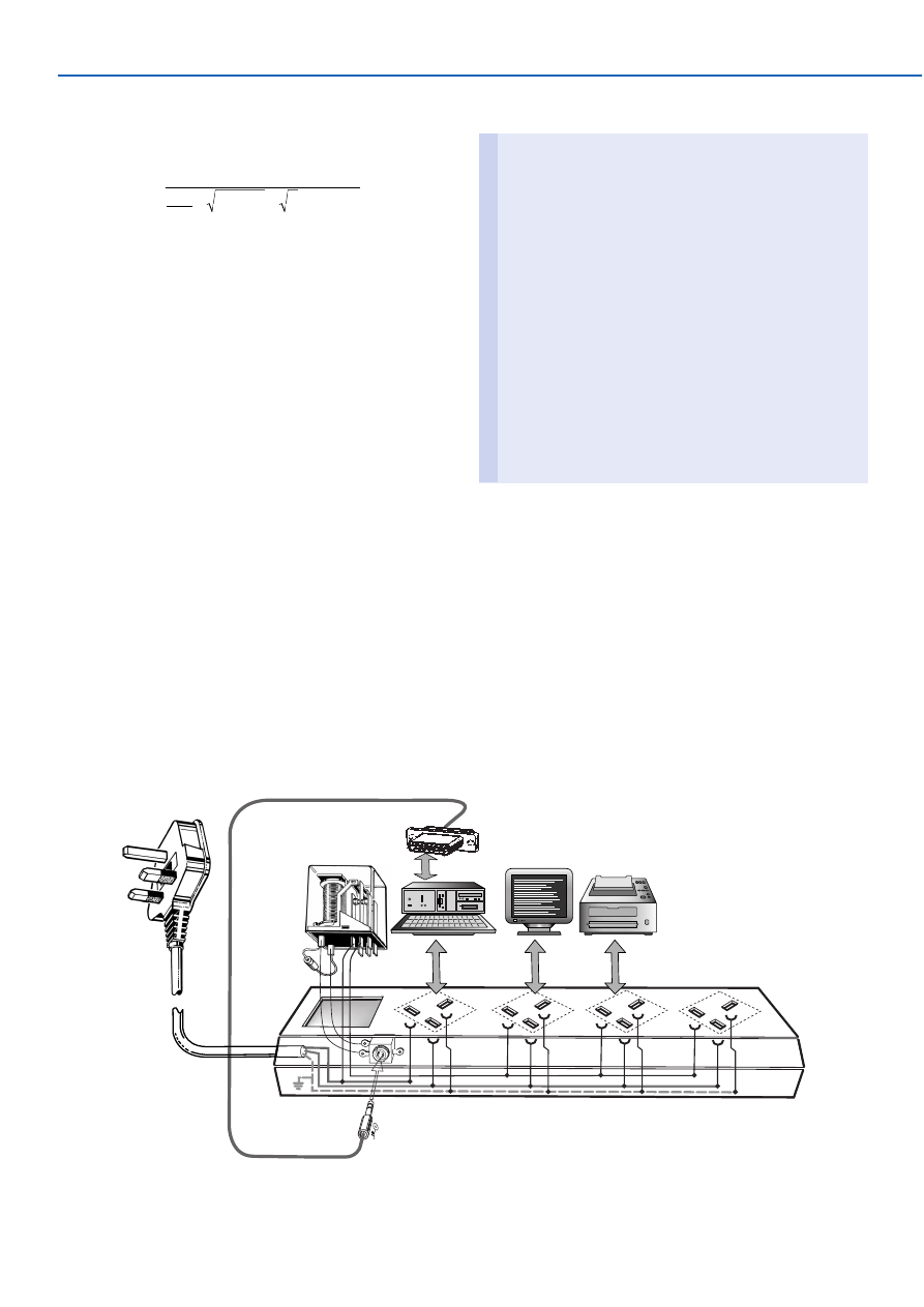
Older PCs had, despite their slowness and other short-
comings, in comparison with their modern descendants at
least one important advantage: they almost universally
046
014004-11
+
+
PIN 1,8,9,15 = +5V
PIN 4,5 = GND
1
15
Computer Off = Monitor Off
were fitted with a switched mains output socket for the
monitor. The main power switch on the PC controlled this
socket, therefore: computer off = monitor off!
Modern PCs make use of a ‘soft’ power switch, which
puts the power supply in standby mode only; as a conse-
quence the switched mains output on the back of the power
supply is usually omitted. Progress therefore, compels the
user once again, to separately switch off the monitor by
hand. Naturally, this is often forgotten.
Fortunately, there is an easy way to do something about
this. It so happens that when the PC is switched on, a
potential of +5 V is present at the game port. Therefore, it
is enough to simply tie a relay to this signal, which then
switches the monitor (and printer, etc.). This uncompli-
cated relay circuit restores an old convention: computer off
= monitor off!
(014004-1)
SUMMER CIRCUITSCOLLECTION
81
7-8/2001
Elektor Electronics
Rev. T. Scarborough
This circuit takes advantage of back-e.m.f. (electromotive
force) to amplify the voltage across a piezo sounder. Ordi-
narily, IC1 would only achieve a gentle beep. However, the
addition of a very high inductance choke of a few Henry —
in this case the coil of a miniature reed relay is used —
achieves a penetrating screech, and represents an easy
method of obtaining considerably more volume in such a
circuit.
The usual protective diode (D1) may be included across
the choke, at the expense of a little volume. In practice, it
was found that no harm was done by omitting D1. The oper-
ating voltage of the relay is immaterial, as long as it is not
less than the supply voltage. Preset P1 should be adjusted
to find the piezo sounder’s resonant frequency. A higher
supply voltage means greater volume — as long as T1’s
ratings are not exceeded.
(010069-1)
047
1
2
3
IC1.A
&
5
6
4
IC1.B
&
100k
P1
R1
10k
C2
47n
R2
10k
T1
BC337
BZ1
D1
1N4001
RLA
+3V...+18V
C1
100µ
25V
IC1
14
7
IC1 = MC14093BCP
010069 - 11
Piezo Amp
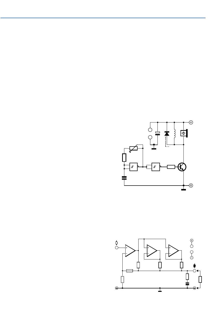
National Semiconductor application note
Some applications notes are real evergreens. This one
originally dates from 1979(!) but has lost nothing of its rel-
evance and is always very interesting when you’re looking
for something like this.
Opamps can only deliver a limited current; typically only
about 10 mA max. When more current is required, several
opamps can be connected in parallel. But this usually does-
n’t work very well because opamps are never 100% equal.
In practice they will fight each other and only get warm,
which was not the intention of course.
048
2
3
1
IC1.A
6
5
7
IC1.B
9
10
8
IC1.C
R1
47
Ω
R4
47
Ω
R5
47
Ω
R6
15
Ω
R
R2
R3
C1
47n
IC1
11
4
+Ub
–Ub
014065 - 11
L
IC1 = LM324
Parallel Opamps
Wyszukiwarka
Podobne podstrony:
e017042
e017040
e017048
e017049
e017043
e017047
e017041
e017044
e017045
e017042
e017047
e017043
e017049
więcej podobnych podstron