SUMMER CIRCUITSCOLLECTION
75
7-8/2001
Elektor Electronics
G.Baars
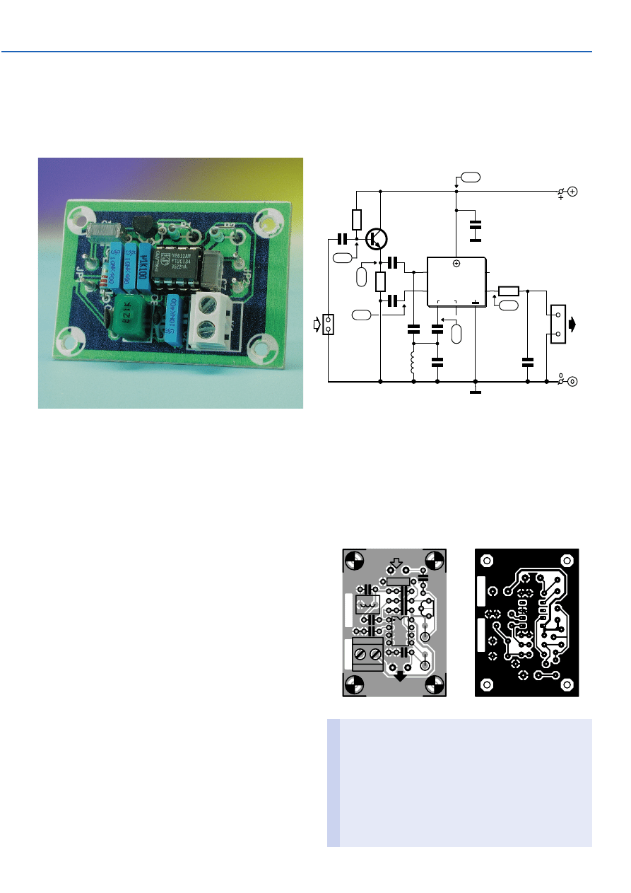
This 455-kHz quadrature detector for narrow-band FM sig-
nals boasts two important advantages: it is pleasantly sim-
ple and it does not require any alignment.
The heart of the circuit is formed by the well-known NE612
IC, which is a double-balanced mixer cum oscillator in an
8-pin DIL package.
The signal is first buffered by T1 and then fed to the input
of the NE612. At the same time, a small portion of the sig-
nal is passed to the mixer via a low-value capacitor (C4).
The operation of the circuit is such that when the input fre-
quency matches the resonant frequency of the parallel L-
C network, the signal on pin 7 has a phase lead of 90
degrees with respect to the signal on pin 2. The phase
angle increases when the input frequency rises and
decreases when the input frequency drops. Since the sig-
nals on pins 2 and 7 are multiplied together, the average
output level is maximum when the signals are in phase and
zero when they are anti-phase. This is the operating point of
the detector. Consequently, an input signal with a varying
frequency produces an output signal with a varying level.
The operating range of the detector is inversely propor-
tional to the Q factor of the parallel resonant network.
This circuit works best with an input signal level of
0.5–2 V
pp
. Since it is linear over a very wide range
(420–500 kHz), it does not need alignment, and normal tol-
erance variations in the values of the inductance and
capacitance in the resonant circuit have little effect. The
output level varies by approximately 1 V over the working
range, so the detection sensitivity is around 13 mV/kHz.
This is adequate for most narrow-band FM applications
with an intermediate frequency of 455 kHz.
The supply voltage may lie between 4.5 and 8 V. The cur-
rent consumption is limited to approximately 2.5 mA. Using
the small printed circuit board shown here, you should
have no difficulty assembling this FM detector in less than
half an hour.
(014002-1)
040
Alignment-free FM Detector
T1
BC547
NE612AN
OUT A
OUT B
IC1
IN A
IN B
OSC
1
2
5
4
8
3
6
7
R1
560k
R2
560k
C5
10n
C6
100p
C7
82n
C8
100n
C1
22n
C3
10n
C2
10n
C4
33p
L1
820µH
JP1
R3
47
Ω
K1
4V5...8V
4mA
014002 - 11
3V5
3V
1V4
6V
4V9
FM
5V3
014002-1
(C) ELEKTOR
C1
C2
C3
C4
C5
C6
C7
C8
H1
H2
H3
H4
H6
IC1
K1
L1
R1
R2
R3
T1
014002-1
+
0
014002-1
(C) ELEKTOR
COMPONENTS LIST
Resistors:
R1,R2 = 560k
Ω
R3 = 47
Ω
Capacitors:
C1 = 22nF
C2,C3,C5 = 10nF
C4 = 33pF
C6 = 100pF
C7 = 82nF
C8 = 100nF
Inductors:
L1 = 820µH
Semiconductors:
T1 = BC547
IC1 = NE612AN
Wyszukiwarka
Podobne podstrony:
e017042
e017048
e017049
e017043
e017047
e017046
e017041
e017044
e017045
e017042
e017047
e017043
e017049
więcej podobnych podstron